Model Interpretation Development: Analysis Design of
Automatic Control System
Guohua Wu, Wenning Liu, Qiuhua Zheng, Zhen Zhang
Hangzhou Dianzi University, Hangzhou, China. Email: [email protected]
Received February 16th, 2009; revised April 10th, 2009; accepted April 14th, 2009.
ABSTRACT
Currently the development of automatic control system is mainly based on manual design. This has made the develop-ment process complicated and has made it difficult to guarantee system requiredevelop-ment. This paper presents a Model in-terpretation development architecture built on meta-models and model inin-terpretation. In this modeling and developing process, different meta-models or domain models may be constructed in terms of various system requirements. Inter-preters are used to transform the meta-model into relevant domain model and generate some other formats from do-main models, typically with different semantic dodo-mains. An interpretation extension interface is introduced, which can be accelerated to develop the model interpreter. This development architecture can improve system reusability and en-hance development efficiency. Finally, an example is introduced to explain the advantage of method.
Keywords:Meta-Model, Model Interpretation, Model-Based Design
1. Introduction
Developing embedded automatic control software is a complicated and time-consuming task nowadays. The growing complication of building and validating soft-ware is a challenge for developers of the embedded software application. The traditional development method based on manual coding is time consuming. Software developers and domain engineers are often from differ-ent fields, and the communication between them is dif-ficult. For acquiring relevant requirement and function, software developer must learn special domain knowledge. However, the requirement may be change during the development process, which will prolong the develop-ment cycle. In addition, the developdevelop-ment of software and hardware is separated, and it is hard to guarantee real-time interaction and verification at target platforms. In order to develop Automatic control software effec-tively, we must reach two goals: firstly, entire software is developed by different domain developer. Secondly, software reusability of automatic control software should be considered.
In the order to solve the problems caused by the tradi-tional approach, the paper presents a method based on model interpretation development for the automatic con-trol system. The meta-model created by modeling tool is considered as domain-specific modeling language through meta-model interpretation. It is a generic model that can
be used to customize application models. Then, it can analyze the domain model and configure parameters and required information. Model interpreter generates output artifacts from domain models, such as code and config-urable files. Using theses artifacts together, it can im-plement embedded automatic control software applica-tion development. In comparison to the tradiapplica-tional ap-proach, it will shorten the cycle of development, reduce the cost of product development and improve the reus-ability of software components.
2. Model Interpretation Developments for
Automatic Control Systems
2.1 Overview of Development Architecture
Model Interpretation Development: Analysis Design of Automatic Control System 117
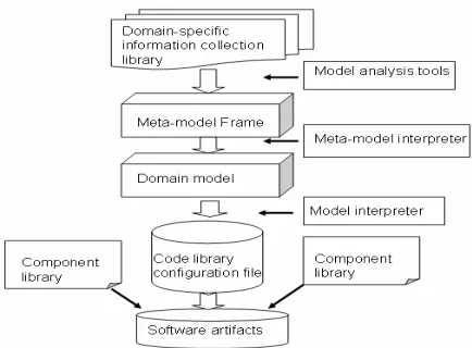
Figure 1. Model interpretation development architecture
Model interpretation development is a technology that is well conformable for the rapid design and implemen-tation of a system. Model interpreimplemen-tation development employs domain-specific models to represent system software, its environment, and their relationship. Model interpretation development have two cores: First, it ex-tends the scope and purpose of modeling in system, and improves the functions of model interpretation through-out the entire development of system process, i.e., design, verification, emulation, code generation. As a result, it can develop the system driven by model. Second, it adopts the domain-oriented concept to analyze com-monness and variety character of the domain system, establishing the meta-model and the domain model to-wards this domain so that it can support uniform devel-opment process. This method provides three functions. 1) It provides the development idea and tools for do-main-specific and creating modeling language familiarly for domain experts. It will be customized quickly based on actual requirement for experts. 2) It separates the module applicable to the embedded automatic control system from multi-aspects design hierarchy. 3) It can relate model paradigm to related format models auto-matically in hardware-independent platforms, thus short-ening the period of software development.
The advantage to using model interpretation develop-ment is the ability to analyze and design a complex sys-tem or software at a high level of abstraction and to con-struct the extension interface to facilitate the design of the model interpretation. Figure 1 shows the architecture of development. The developer collects the related do-main information from information libraries and con-structs the meta-model of needed domain using existing modeling tools. This is the first step. The developer cus-tomizes the paradigm of meta-model, the paradigm de-fines the entities and associations in the given domain. Related models are assembled into classes. Each class has its own model hierarchy. Paradigm has a fixed set of class. Then, they can design the domain model
employ-ing meta-model interpreter, transform these models into essential code, configurable files and verification infor-mation documentation using model generator engines, i.e., model interpreter. For example, this model generator engine can translate GME [3] models into UPPAAL [4] models and these models can be simulated in UPPAAL model, Finally, output information documentation or artifacts deploy some component libraries to synthesize the software or documents customer want to use con-veniently.
2.2 Creation of Meta-Model
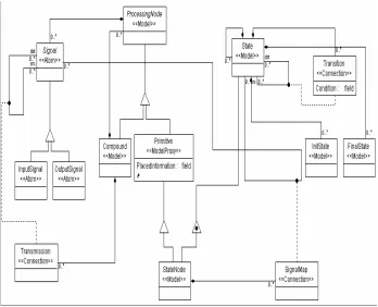
Developer can construct any of meta-model in a domain employing the meta-modeling language, e.g., meta-model in vehicle, or navigation. Meta-model layer is the foun-dational and core layer in the implementation of do-main-specific environment. Figure 2 shows the meta- model paradigm created by GME [5]. In this figure, the root model is the Compound <<Model>>. This com-pound contains ProcessingNode <<Model>>, which means that it has all of the properties from the Process-ingNode. In the meantime, the Compound and the Primi-tive are inherited from ProcessingNode which contains Signal <<Atom>>. The signal genrates two types of node: Inputsignal <<Atom>> and Outputsignal <<Atom>>. The two types of node represent input and output of sig-nal respectively. The input and output are connected by Transmission <<Connection>>.
This figure also presents a relationship of state transi-tion. The State <<Model>> has its own models and con-tains two types of node: Initstate <<Atom>> and Final-State <<Atom>>, which are represented by InitFinal-State and FinalState respectively and are associates with each other by Transition <<Connention>>. There is a special node called StateNode <<Model>>. It is inherited from Primi-tive and State and has all of the properties from the ProcessingNode and State. StateNode has a SignalMap <<Connection>>. This means that Signal can connect with State. This diagram denotes that state can transform into another state by invoking the correlative signal of sensor in the real environment.
2.3 Domain Model Design
The designer of domain model should be familiar with this domain and it’s essential consideration that develop-ers communicate with domain experts in time.
Figure 2. Screenshot of the resource meta-model created using GME
eral, it is not obvious how it can be implemented [7]. the order of processing for an application. Each
compo-nent in the signal and state flow graph receives data from other components, performs some data exchange, and then outputs new data to other system components.
The model interpreter is usually implemented in three ways [8].
1) Direct implementation. The generator acts on the mapping between abstract syntax of input model and abstract syntax of the target model. The structure of input tree is the data structure that corresponds to the output tree of compilers, and the structure of target tree corre-sponds to the output tree of compilers. Naturally, in the simplest of cases, the output artifacts can be directly generated from the input tree.
2.4 Model Interpretation
Model interpreters [6] i.e. model generators play a cru-cial key in model interpretation development. They act on the transformation engine in software development.
Model interpreters are used to transform the informa-tion captured in the models into the artifacts required by the chosen analysis tools or run-time system. Model generators have two functions:
1) To transform models into the input file and infor-mation of analysis tools or to transform the analysis re-sults back into the modeling language.
2) To transform models into needed code, static data structure, and configuration files, etc. These can form the executable software system running on some integration platforms (OS, component integration framework, etc.). Figure 3 shows the relationship between models and gen-erators.
The model interpretation process is somewhat similar to the back-end of compilers. The models capture infor-mation in a structured form, typically in the form of hi-erarchically organized objects. This graph of objects may be traversed, perhaps transformed, and used to generated
[image:3.595.313.538.532.703.2]Model Interpretation Development: Analysis Design of Automatic Control System 119
2) Visitor –based approach
A visitor object implements the actions to be per-formed all sorts of nodes in the input tree, while the tree nodes receive the visitor object and call the appropriate, special node operation on it. The visitor pattern allows the concise and scalable implementation of generators, both for the translation and the output phase. Generators using this approach are very simple, understandable and have successfully applied in different modeling envi-ronment.
3) Meta-generators. A better technique would allow the mathematically precise definition of the generator’s internal operation and the code generation of the genera-tor from correlation model.
Although the pattern-based approach is better than di-rect implementation, essentially speaking, it belongs to the category of direct implementation. Based on meta- generator approach, the mechanism of internal inter-preter can be abstracted, which can be more structured in development. Common parts of interpreter can be gener-ated automatically by meta-generator; developers can focus on the mapping between input and output data.
A generator can be created in terms of a graph tra-versal which describes in what order the nodes of the input tree should be visited. Additionally, a set of trans-formation rules should be added. Acquiring data struc-ture and traversing input tree of models is a significant process for the development of model interpreter.
In order to be more effective, we use interpretation extension interface (IEI) to improve the effectiveness of developing interpreter. Interpretation extension interface extracts most of the functions. Configuration and analy-sis of the functions are time-consuming. The interface provides the extensibility to conform with both main-specific modeling simulations or analyses and do-main-independent traversal, code framework generation or graph transformation [9,10]. Such a structure based on the method of meta-generator must encapsulate functions or algorithms that are useful in a wide variety of univer-sal environments. However, an IEI is not just a set of functions. Rather, in the way of predefined pattern, it is a flexible component that can be extended and enhanced based on design requirement.
Common basic parts of domain-independent structures depend on which types the IEI can operate or select. Domain-specific functions or detailed implementations are completed by interpretation extension interface. An IEI can be constructed that utilizes unified interface specifications.
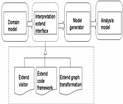
Interpretation extension interface enables a designer to implement the skeleton of domain-specific model inter-preter. The different functions of implementation are abstracted by a categorized common interface. The input models required by a given analytic domain can be de-termined by selecting the type of the implementation of
an IEI and extracted the information (e.g., traversal, code framework, graph transformation) from the model using the APIs which provides by the modeling tools. The en-capsulated algorithms or functions are invoked at spe-cific times during the interpretation process, under such a condition that the traversal information, generated code will be invocated when various assigned events occur during an actual interpreter run. Figure 4 shows high- level design of the interpretation extension interface.
[image:4.595.320.524.321.494.2]IEI can provide extended interface to the developer of interpreter so that they can be convenient to design the appropriate interpretation for software development or model analysis. Furthermore, GME offers interface based on the component object model (COM) technol-ogy, which can facilitate for developer dependent on the IEI to design and construct model interpreter rapidly. Figure 5 shows development of GME interpreter hierar-chy.
[image:4.595.316.532.546.704.2]Figure 4. High-level design of the interpretation extension interface
3. Case Study
Using the approach discussed above, a simple example of Washer model graph illustrates the interpretation ca-pability of model design. Figure 6 is a screen shot of Washer model graph. It illustrates the domain models built in the graphical user interface of GME.
According to the meta-model defined above, an im-plementation model has been created by GME. These implementation models define and design the structure of system components and the associations between them.
The example contains six states and signals. The sig-nals are a source actor denoted as “sensor” and the states are a sink denoted as “Actuator”.
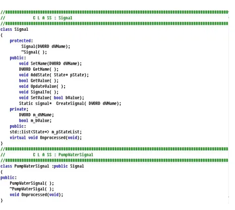
[image:5.595.68.273.351.479.2]Each signal model will send one signal to inform the state model to change its action so that Washer can switch to the next step to execute the operation. Figure 7 illustrates a sample output code after executing the inter-pretation extension interface in the model paradigm about this example model. Model interpreter will parse the required parameters or information from the resource
Figure 6. Screenshot of Washer model graph application
Figure 7. Screenshot of output code from generator
model of component and configure the simulator [11]. The C files specified as part of the application model, also can be compiled with the compiler of plat-form-independent. The simulation results can be veri-fied degree of satisfaction of the performance.
The configuration file also can be output, and then the generated code and configuration file are read and parsed by the runtime platform. The runtime platform configures system requirements and other data structures based on this configuration file and code file. For the sake of sim-plicity, executed functions are given in code in Figure 7.
Finally, the generated C code would be checked by the compiler during compilation on the runtime platform. The generated code is compiled, linked and synthesized. The developer will develop software artifacts by using the C code.
4. Conclusions and Future Work
This paper presents model interpretation development architecture for the automatic control system and uses a tool chain to support the convenient and rapid develop-ment. The case study has shown that this method can improve system reusability, reduce the cost of products, and gain the expected effect.
In the future, we should do the following work. 1) Domain meta-model needs to be more effective. We should design more understanding models in this domain, communicating with domain experts for accumulating experience. 2) Model interpretation extension interface needs to enhance the functionality of resources traversal, code generation and model transformation. We will pro-vide broad coverage of the analysis techniques present in the software architecture. This is the core work in our research. 3) A research tool kit should be emulated, veri-fied, tested and analyzed in the development of auto-matic control system so that it can integrate more related tools to support automatic assemblage. This is an oner-ous task.
5. Acknowledgements
This work is supported by National Fundamental Re-search Program of China under Grant NO.A1420080190.
REFERENCES
[1] Object Management Group, “Model driven architecture: A technical perspective,” 2001.
[image:5.595.58.291.503.711.2]Model Interpretation Development: Analysis Design of Automatic Control System 121
[3] A. Ledeczi, et al., “The generic modeling environment,” Workshop on Intelligent Signal Processing, Budapest, Hungary, May 17, 2001.
[4] K. G. Larsen, P. Pettersson, and W. Yi, “Uppaal in a nutshell,” International Journal on Software Tools for Technology Transfer.
[5] GME 2000 User’s Manual, available from http://www. isis.vanderbilt.edu.
[6] G. Edwards, N. Medvidovic, et al., “Model interpreter frameworks: A foundation for the analysis of domain- specific software architectures,” [J] Journal of Universal Computer Science, Vol. 14, No. 8, pp. 1182-1206, 2008. [7] G. Karsai, “Structured specification of model interpret-ers,” IEEE Conference and Workshop on Engineering of Computer-Based Systems, Proceedings ECBS’99, 1999.
[8] G. Karsai, J. Sztipanovits, A. Ledeczi, et al., “Model-in-tegrated development of embedded software [J],” Pro-ceedings of the IEEE, 2003.
[9] K. Chen, J. Sztipanovits, S. Abdelwahed, and E. Jackson, “Semantic anchoring with model transformations,” pp. 115-129, 2005.
[10] M. Wimmer, M. Strommer, et al., “Towards model trans-formation generation by-example,” in Proceedings of HICSS-40 Hawaii International Conference on System Sciences, Hawaii, USA, 2007.