Cryptanalysis of a Substitution-Permutation Network
Using Gene Assembly in Ciliates
Arash Karimi, Hadi Shahriar Shahhoseini*
Electrical Engineering Department, Iran University of Science and Technology, Tehran, Iran Email: [email protected], *[email protected]
Received November 26, 2011; revised January 12, 2012; accepted January 27, 2012
ABSTRACT
In this paper we provide a novel approach for breaking a significant class of block ciphers, the so-called SPN ciphers, using the process of gene assembly in ciliates. Our proposed scheme utilizes, for the first time, the Turing-powerful potential of gene assembly procedure of ciliated protozoa into the real world computations and has a fewer number of steps than the other proposed schemes to break a cipher. We elaborate notions of formal language theory based on AIR systems, which can be thought of as a modified version of intramolecular scheme to model the ciliate bio-operations, for construction of building blocks necessary for breaking the cipher, and based on these nature-inspired constructions which are as powerful as Turing machines, we propose a theoretical approach for breaking SPN ciphers. Then, we simulate our proposed plan for breaking these ciphers on a sample block cipher based on this structure. Our results show that the proposed scheme has 51.5 percent improvement over the best previously proposed nature-inspired scheme for breaking a cipher.
Keywords: Nature-Inspired Computation; Accepting Intramolecular Recombination (AIR) Systems; Cryptanalysis;
Gene Assembly; Block Ciphers
1. Introduction
L. Adleman, during a laboratory experiment, for the first time discovered the potential of DNA molecules to solve computationally hard problems [1]. His revolutionary paper started the interdisciplinary area of DNA comput- ing. Since then, a bulk of research has tried to concen- trate on the theoretical ability of DNA strands to solve hard problems. Specifically, language theory has helped researchers find mathematical constructions to build com- puting machines based on ability of biomolecules repre-sented in form of words. Natural computing which util-izes the potential of biomolecules in their living envi-ronments (i.e. cells) is of special interest. In this respect, Kari et al. in [2,3] considered the gene assembly process in ciliates and demonstrated that it has computational capability just like Turing machines. Their findings aroused a hot line of research in cellular computing.
Ciliates are single-celled eukaryotes that have special features which make them appealing and distinctive. They possess cilia which are used for their motion and also for making a current of water to sweep bacteria and other nutrients into their oral cavities. In addition, they have two different sorts of nuclei: A diploid micronu- cleus and a polyploid macronucleus. The former is germ-
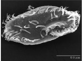
line nucleus which is activated only during the sexual process of conjugation and remains dormant in the vege- tative cycle. And the latter is the somatic nucleus which is the housekeeping nucleus responsible for production of RNA transcripts which is a must for cell development during its life cycle. A species of ciliated protozoa Oxy- tricha trifallax is shown in Figure 1.
Ciliates do sorting, inversion and excision of their DNA sequences. We adopt the strategy of encoding all solution candidates into a micronuclear gene, then as- sembling the gene using intramolecular model [4] and ultimately filtering the results and checking through the cipher to find the right key.
In [5], Adleman et al. proposed a scheme to break the Data Encryption Standard using DNA molecules, by molecular biology tools.
In this paper we want to replace formal biological op- erations by ciliate bio-operations for cryptanalysis of SPN ciphers. For this reason, we use language-theoretic notions to describe the process of cryptanalysis and by utilizing an encoding scheme of the words of our con- structed notion to the MIC genes of a hypothetical cili- ated protozoa from the Stichotrichous family as shown in
Figure 2, we design AIR systems which simulate dif-
Figure 1. Ciliated protozoa Oxytrichia trifallax.
Figure 2. Ciliated protozoa Stichotricha.
networks and then using these Turing machine construc- tions, we simulate our theoretical attack on this structure defined by specific and predefined blocks.
The rest of this paper is organized as follows. In Sec- tion 2, the substitution-permutation networks are intro- duced which constitute a large class of block ciphers, in Section 3.1, the concept of splicing schemes that is nec- essary to understand AIR systems which is a variant of intramolecular operations for modeling ciliate bio-op- erations is briefly introduced. In Section 3.2, we define the accepting intramolecular recombination systems (or AIR systems) on which our proposed scheme to break the cipher is based. In Section 4, we propose and build the necessary blocks which we need for cryptanalysis of the cipher. In Section 5, based on our previously designed AIR systems, we devise a theoretical approach to attack the cipher. In Section 6, we evaluate the performance of our proposed scheme and derive the total bio-steps nec- essary to mount the attack. In Section 7, our simulations are discussed and the results are reported. Finally, in Sec- tion 8, we summarize our paper and conclusions are drawn, and the plans for the future research based on this work are presented.
2. Substitution-Permutation Networks
A variety of modern block ciphers are built using an it- erative structure of Substitution-Permutation Networks or SPN for short. AES (Rijndael), Shark, Khazad and Anu-
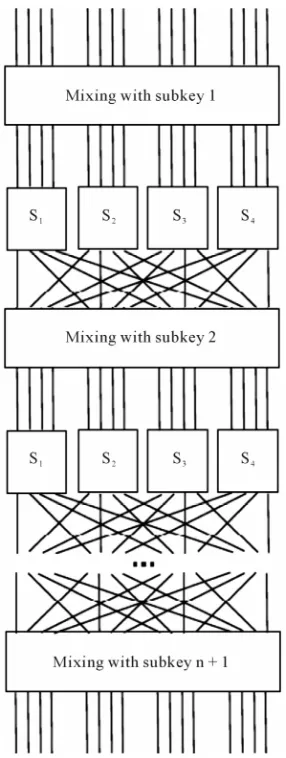
bis are good examples for SPN ciphers [6]. The selected example SPN is as shown in Figure 3 and we will fo- cus our discussion on this network. As demonstrated in Figure 3, the block size of our cipher is 16-bits and each block of the plaintext is processed by repeating basic operations of a round which are substitution, permutation and key mixing. Indeed, our considered scheme is similar to what is found in many modern block ciphers including Rijndael from basic operations viewpoint and provides us with an insight into cryptanalysis of the real-world block ciphers using natural computing methods.
3. Preliminary Definitions
Our proposed scheme to break the cipher is based on Accepting intramolecular recombination systems (AIR systems) which is a variant of intramolecular models of gene assembly in ciliated protozoa. In this section we bring some basic notions and notations that are necessary to conceive the attack procedure.
3.1. Splicing Schemes
A splicing scheme [7] is defined as a pair R , ~
in which is an alphabet and ~ is a binary relation over
* *
2
. Assuming that this relation exists between two triples of strings as follows , ,p ~
, ,p
z x p y
we say that given the abovementioned binary relation, strings 1 and z2y p x can be ob-
tained by recombination from xx p x
y y p y
and
.
3.2. AIR Systems
An accepting intramolecular recombination system is defined as a quadruple G
, ~, in,
in which
, ~
R is the splicing scheme and in and are
input and the target words, respectively. Considering a splicing scheme, R
, ~
*
, , , , , , ,
x u u v x y y z
, we define the contextual intramolecular operations of translocation, trl,and dele- tion, del, which are generalizations of dlad and ld in- tramolecular operations, respectively, as follows [8].
Assuming and xx ,
uqyuu , vqz v , xpux
ypv y y
,
, z z
The trl operation with re- spect to R is defined as
trlp q,
xpuqypvqztrlp q, xpvqypuqz (1)Therefore, in the p q, operation the strings of u and
v which are flanked by pointers p and q are swapped. The
del operation with respect to R is also defined as:
trl
delp xpupydelp xpy (2)
, ,p
~ , ,p
where x u u , , , *
and for
,
, xx uuu , y y . Hence, intuitively,
Figure 3. The basic substitution-permutation network.
if the contexts of occurrences p are in the relation ~, the
p
del
R operation removes the string u that is flanked by two occurrences of p. We can now define the set of all contextual intramolecular operations under guidance of ~ as:
, m p q m, ,
*
w
,
p q
R trl del (3)
Accordingly, we can define the language that is ac- cepted by the AIR system, G, as all the words
opR inw
for which by consecutive application of any number of operations from , we can get to the target word .
4. Constructing Necessary Building Blocks
for Attacking the Cipher
Our proposed scheme to break the SPN family of block ciphers considers the modified approach of intramolecu- lar recombination for modeling gene assembly process in ciliates, and then applies this approach in constructing necessary building blocks for breaking the cipher. Our
attack approach is brute force in which we assume that we possess a (plaintext, ciphertext) pair and by exhaust- tive search over all possible keys, we aim to find the correct key of the cipher. Therefore, in the first step, we should produce all genes of a hypothetical ciliate each of which codes for an individual key of the cipher and then using gene assembly process that naturally happens in ciliated protozoa, we construct Turing machines that imitate main operations that we need in the procedure of cryptanalysis such as the substitution, permutation and logical XOR, and ultimately, we can find the key that when mixed with the plaintext, gives the ciphertext if in each step of the computation the micronuclear (MIC) genes are assembled to the expected macronuclear (MAC) genes. In the next section we introduce the main opera- tions needed for cryptanalysis and then, build Turing machines that imitate these operations.
4.1. Generation of All Possible Keys
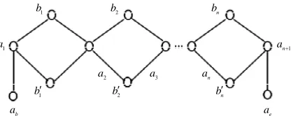
In order for generation of all genes that code for all pos- sible combinations of the key, we utilize the graph of
Figure 4 in which all possible paths that start from b
and terminate at e code for a different n-bit key. We
use intramolecular model of gene assembly in ciliates. Therefore, beginning with a single MIC gene pattern for which there exist more than two occurrences of a pointer, we can assemble different MAC gene patterns that code for different keys of the cipher. Now, assuming that graph of Figure 4 is demonstrated with
a a
,
G V E for which V and E denote sets of vertices and edges, re- spectively, we define an encoding of G in the MIC gene pattern in terms of MDS descriptors as follows: we asso- ciate a pointer p to each vertex of G and to each directededge
p q,
p q,
n
pp p p q
we associate MDS of . Therefore, a path 1 2 of G can be encoded by an interme-
diate MDS
p p p, p q,
p s 1 2 k in which p and q are the
incoming and outgoing pointers, respectively, and i ,
1 i k are those pointers for which MIC MDSs that correspond with edges
p p, 1
, p p1, 2
,,
p qk,
be- longing to set of edges of G, have been spliced. Note that MIC MDSs are spliced on their common pointers. For our graph of representation of all possible keys (graph of Figure 4) we have
b, 1, , ,1 1 , n, n, n, n 1, e
V a a b b a b b a a
and
1 1 1 1 1 1 2
1 2 1
, , , , , , , ,
, , , ,
b
n e
E a a a b a b b a
b a a a
hence, for instance, we associate an MDS
b 1 1 2 2 n1 e
to a path a ab 1 1 2 2 n1 e andwith different strategies to the same MIC gene pattern, we can obtain different MAC genes which represent all
, ,
IJCNS Copyright © 2012 SciRes.
2
a
2
b bn
3
a an
b a
1
a
1
b
e a
1
n a
1
b b2 bn
a a
[image:4.595.69.277.86.169.2]
a u ab, , e
1 i n 1
Figure 4. The graph for generation of all possible keys.
possible keys. According to the universality result of [9] for intramolecular operations, each path of G can be as- sembled using intramolecular ciliate operations ld, hi and
dlad. Since we are looking for all those paths that start from b and end at e, our desired assembled MAC
gene would be of the form, , in which u is any path that contains all ai’s
and all differ-ent i’s or i’s . Therefore, if each edge of G
is encoded as a MIC MDS then, we show that one can produce all possible keys of the cipher using ld operation only from a single string of MDS descriptors that dem- onstrate all edges of G as shown in Theorem 1. For this reason, we say that a descriptor
b b
1 i nG
is associated to G if it is of the form
a , ,a1
2
1, ,
wheren
G an ae
p q, E
ld ld
p, , q
G b
G
is defined as a descriptor that en-codes all edges of G.
Theorem 1. Any successfully assembled
ld G
MDS n1 a
b
for which all i’s and a total
number of n of either bi’s or i’s appear and
2
MDS V , produces any possible path that is rep- resentative for every one of possible keys of the cipher.
Implementation of logical XOR using ciliate bio
operations is explained in Section 4.2. MDS V 2, produces any possible path that is representative for every one of possible keys of the cipher.
Implementation of logical XOR using ciliate bio operations is explained in Section 4.2.
4.2. An Intramolecular Model for Computing Logical XOR
We define logical XOR as satisfiability of a Boolean relationship that is depicted in Equation (4).
C xy xy (4)
And here we provide a ciliate solution for Equation (4) using intramolecular model which computes the result of XOR in polynomial time. For this reason, we construct an AIR system G
, ~,0,YES
[9] that evaluates the output of Equation (4). The circuit that implements XOR is depicted in Figure 5.As can be seen in Figure 5, the circuit is composed of three layers and we show its output with the following notation demonstrated in Equation (5).
c31 c21 [c11 ]c11 c21 c22[c12 ]c12 c22
c31c x y x y
c
th
i
(5)
In the above notation, each gate is shown with ij in
which i denotes number of layer of the circuit and j de- notes number of that gate in the layer and and
and
denote logical AND, OR and NOT gates,respectively. In this circuit we have C
V E,
where
11, 12, 21, 22, 31
V c c c c c and
,
, ,
,
,
, ,
E c11 c21 c12 c22 c21 c31 c22 c31 . Now we con- struct an AIR system for the Boolean circuit of Figure 5 as Gc
V, ~,YES
where
11 11 12 12 21 21 22 22 31 31 11 12 21 22 31
, , , , , , , $ [ , ] ,[c c c , ] ,c c , c , c , c , (c , )c , , , , ,
V V X Y T F Y E S
$
YES is the axiom and and are not included in alphabet of the Turing machine. Furthermore,
V, ~
is the splicing scheme. Assuming that F is used instead of logical zero and is used instead of logical one, xand y are encoded into inputs for by utilizing the mapping
T
c
G
i T F,
i
x y,
in which is the set
of inputs of the circuit. Now, if we consider Equations (6) and (7):
31 21 11 11 21 22 12 12 22 31
1 (c 31 c 21 x [c 11 y 11]c 21 c c 22 [c 12 x 12]c y 22 c 31)c
(6)
11 12
12
12
12 21
21
21
21
22 22 22 22 31 31 31 31
] $ [ ] $ [ ( )] $ $
$ $ $( ) $( ) $
c c c c c c c c c c
c c c c c c c c
y x x x y x y
x y x y x y x y x y x y
G11 11 11
2 $ [c y ] $ [c
(7)
,[ ,c11 11 11u 11
~ $,[ ,c11 T
, T, ij Sub u
11The input of our AIR system c is then
0 1 2
(8)
YE ES
and Gc accepts the input string if re-
sult of XOR is 1 and the axiom YES is produced. There- fore if result of XOR equals 1, Gc accepts input string in 4 steps. In the following we construct splicing schemes necessary for computation of XOR in the proposed AIR system.
11 11u 11, ] ,c11
~ T, ] , $ ,c11
T, ij Sub u
11 (9)
11 11 11 11 11
11 11
,[ , ~ $,[ , ,
,
c c
ij
u F
T Sub u Sub u
11
c c12
21 c
22 c
, c21,21 21u 21
~ $,c21,F
, FSub u
21C 31 c x
y
Figure 5. Operation of XOR.
11
11 11 11 11
, ] ,
, ij
T Sub u
11 11 ~ , ] , $ , c c u F Sub u
ij Sub u
12
T ij Sub u
12
12
12
,[ , u ~ $,[c ,F ,
Sub u
12 12 12 ~ , ] , $ , c c u F Sub u
, 21,
,
21u T FSub u
FSub u
21(11)
,[c12,12 12u 12
~ $,[c12,T , T, (12)
12 12u 12, ] ,c12
~ T, ] , $ ,c12 ,
(13)
12 12 12 12
12 ,
c
ij
TSub u
12 1212, ] ,
(14)
12 , ijTSub u
, c21,21 2121
~ $ c(15)
(16)
21 21u 21, c21,
~ T,c21, $ , (17)(18)
21 21u 21, c21,
~ F,c21, $ ,
FSub u
21 (19)
, c22,22u2222
~ $,c22,T
, FSub u
22 (20)
22u22 22, c22,
~ T,c22, $ ,
FSub u
22 (21)
, c22,22u2222
~ $,c22,F
, FSub u
22 (22)
22u22 22, c22,
~ F,c22, $ ,
FSub u
22 (23)
31 31 31 31 31
31 31 , ( , ~ $, ( , , c c ij u T
T Sub u Sub u
(24)
31 31
31 31 31
31 31 , ) , ~ , ) , $ , c c ij u T
T Sub u Sub u
(25)
, (c31,31 31u 31
~ $, (c31,T
, T, ij Sub u
31 (26)
31 31u 31, )c31,
~ T, )c31, $ ,
T, ij Sub u
31 (27)
Y E, ,(c31T)c31
~ $, ,
E S
, if result is one, 1 , 3
ij
u i j
11
21 22 12
12
22, , 1
, 1, 2
, 2, 1
, 2, 2
[ ]c c c [c ]c c , 3, 1
y i j
x i j
y x i j
x y i j
y x x y i j
(28)Furthermore, in Equations (8)-(28) are
defined as shown in Equation (29).
11 11
[c ]c
ij
u
12 12
21 11
[c ]c
c c
(29)
and the computed words in each step of computation can be written as Equations (30)-(33):
31 21 11 11 21 22 12 12 22 31
12 12 12 12 21 21 21 21 22 22
0 ( 31 21 [ 11 11] 21 22 [ 12 12] 22 31)
$[ ] $[ ] $[ ] $[ ] $ $ $
c c c c c c c c c c
c c c c c c c c c c
YE x y x y
y y x x x y x y x y
y x
11 11 11 11
22 22 31
$ $ (
c c c c
c x y c c x
(30)
31 31 31
)c $ (c )c $
y x y x y ES
31 21 11 11 21 22 12 12 22 31
11 11 12 12 12 12 21 21 21 21
22 31
1 31 21 21 22 22 31
12 12
( [ ] [ ] )
$[ ] $[ ] $[ ( ) ] $[ ] $ $
$ $ $ (
c c c c c c c c c c
c c c c c c c c c c
c c c
YE x y x y
y y x x x y x y
x y x y
11 11
22 22 22
11 11
c c
c x y c
(31)
xy
)c31$ (c31
xy
xy
)c31$ES
31 21 21 22 22 31 11 11 11 11
12 12 21 11 11 21 21 21
22 22 22 31
2 31 31 11 11
21 21
22
( ) $[ ] $[ ]
] $ [ ] $ )
$ $ (
c c c c c c c c c c
c c c c c c c c
c c c c
YE x y x y y y
x x x y x y
x y x y x y
12 12
22 12 12
12 12
22
$[ ] $[
$ [ ]
c c
c c c
31 31
$ (c xy xy )c $
31 31 11 11 11 11 12 12 12
21 11 11 21 21 21 22 12 12 22 22
31 21 21 22 22
3 11 11 1
21 21 22 22
31
( ) $[ ] $[ ] $[ ] $[
$ [ ] $ $ [ ]
$ (
c c c c c c c
c c c c c c c c c c
c c c c c
YE x y x y y y x
x y x y x y
x y x y
12
22
2 12 ]
$
c c c
c c x x y
31 31 31
31)c $ (c xy xy )c $ES
(33)
In the next step, by applying deletion operation to 2,
if the result of the computation equals one, the axiom
YES will be produced.
4.3. Simulation of S-Box with AIR Systems
We assume the word of Equation (34) as input to S-boxes of Figure 3
1 1 1 2 2 2
4 4 4 1 1 1 2 2 3 3 3 4 4
{ } { }
{ } ${ } ${
${ } ${ } ${
${ } $ !, 1 4
i
S i i i i i i i i i i i i i i i i
OK x x 3 3 3
1 2 2 3 4 4
{ }
} ${ }
} ${ }
i i i i i i i i i
i i i
x
x T F T
F T
in of
F T
F K i
(34)
The following splicing rules will be used to guide re- combinations of our AIR system for simulating S-boxes.
,{ , ,1i x1i
~ $,{ ,1i T
if x1i T LUT Siin of i
(35)
x1i,} ,1i
~ T,} , $ if1i
x1i
T LUT S
in of i
(36)
1 1 1 1
,{ , ,i xi ~ $,{ ,i F if xi
,} ,
~ ,} , $ if
F LUT S
in of
(37)
1i 1i 1i 1i i
x F x F LUT S
in of i
(38)
,{ , ,2i x2i
~ $,{ ,2i T
if x2i T LUT Sin of
(39)
x2i,} ,2i
~ T,} , $ if2i
x2i T LUT Siin of
(40)
,{ , ,2i x2i
~ $,{ ,2i F
if x2i F LUT Siin of i
(41)
x2i,} ,2i
~ F,} , $ if2i
x2i F LUT Sin of
(42)
,{ , ,3i x3i
~ $,{ ,3i T
if x3i i
,} ,
~ ,} , $ if
T LUT S
in of i
(43)
3i 3i 3i 3i
x T x T LUT S
in of
(44)
,{ , ,13 x3i
~ $,{ ,3i F
if x3i F LUT Siin of
(45)
x3i,} ,3i
~ F,} , $ if3i
x3i F LUT Siin of i
(46)
,{ , ,4i x4i
~ $,{ ,4i T
if x4i T LUT Sin of
(47)
x4i,} ,4i
~ T,} , $ if4i
x4i T LUT Siin of
(48)
,{ , ,4i x4i
~ $,{ ,4i F
if x4i F LUT Siin of i
(49)
x4i,} ,4i
~ F,} , $ if4i
x4i F LUT S
1 1 2 2 3 3 4 4
1 1 1 1 1 2 2 2 2 2 3 3 3 3 3 4 4 4 4 4
{ } { } { } { }
${ } ${ } ${ } ${ } ${ }
${ } ${ } ${ } $ !, 1 4
i
S i i i i i i i i
i i i i i i i i i i i i i
i i i i i i i
OK T T T T
x F x F x
F x F K i
(50)
As can be seen in splicing relations of S-boxes, trl op- eration is applied to the input word in a parallel fashion in accordance with the look-up table of the correspond- ing S-box and therefore, all input bits are assigned a True
or a False value at the same time.
After applying the above splicing rules, the following word is obtained in which we assumed that the 4-bits of input in S-box i are all mapped to logical one or T. Other mappings can be defined as well according to the look-up table of each S-box.
(51)
Then, the following splicing scheme is applied to the resultant word. Then, the following splicing scheme is applied to the resultant word.
O K, , { 1iu1i}1i{2iu2i}2i{3iu3i}3i{4iu4i}4i
~ $,K,!
2
i K
S del
(52) After applying the above rule, a deletion rule (which is based on ld operation) is applied as follows.
(53)
Therefore, axiom OK! Is produced which implies that the S-box has been calculated.
The start sequence for calculation of the substituted words for computing S-box can be written as shown in Equation (54), in which p and
1 1 1 2 2 2 3 3 3 4 4 4
1 1 1 1 2 2 2 2 3 3
3 3 4 4 4 4
{ } { } { } { }
${ } ${ } ${ } ${ } ${ }
${ } ${ } ${ } $
i
S i i i i i i i i i i i i
i i i i i i i i i i
i i i i i i
x x x x
p T F T F T
F T F p
i S
are assumed blank symbols.
(54)
After applying the splicing rules of Equations (35)-(50) to we can obtain Si as written in Equation (55).
1 1 2 2 3 3 4 4
1 1 1 1 1 2 2 2 2 2 3 3 3 3 3 4 4 4 4 4
{ } { } { } { }
${ } ${ } ${ } ${ }
${ } ${ } ${ } ${ } $
i
S i i i i i i i i
i i i i i i i i i i
i i i i i i i i i i
T T T T
p x F x F
x F x F p
(55)
Now, we can obtain the output of S-boxes by applying a deletion rule which is guided by the splicing scheme which is written in Equation (56).
1 1 1
2 2 2 3 3 3 4 4 4{ } { } { } { } , , $
~ $, ,
iui i iui i iui i iui i
(56)
In Equation (56), shows the blank symbol and
,
, , 1, , 4uji T F i j in which j is the number of
output bit of S-boxes and i is number of S-boxes. There- fore, after applying the above rules, we can write the output of S-boxes as shown in Equation (57).
1 1 1 2 2 2 3 3
{ } { } {
i
S iui i iui i i i
u }3i{4iu4i}4i
, , 4
i
i
S
(57)
In Equation (57), uji
T F,
, j 1, and is the output of S-box number i.
4.4. Simulation of P-Box with AIR Systems
In this section, we build a Turing machine based on AIR systems that simulates P-boxes of Figure 3. For this rea-son, we write the input word and splicing schemes for P-box as shown in Equation (58).
1 1 1 2 2 2 1 1 1 2 2 2
1 16
{ } { }
${ } ${ } $
, , , 1 16
P
i
x x
p u u
u x x i
16 16 16 16 16 16
{ }
${ } $ ,
x
u p
u 1 i 16
$ , 1 16
i
u i
16 16 16 16 16 16
{ }
{ } $
16
u p
u p
P
(58)
In the above equation which describes input to the P-boxes of “Figure 3”, we further assume that all i,
are distinctive and p is the blank symbol. Therefore, we can write the splicing schemes as shown in Equation (59).
,{ ,i xi
~ $,{ ,i ui
, xi,} ,i
~ i,} , (59) After applying trl rules in a parallel fashion, such that they are guided by splicing rules of Equation (59), we can get to the word that is shown in Equation (60).
1 1 1 2 2 2 1 1 1 2 2 2
1 16
{ } { }
${ } ${ } $ $
, , 1
,
P
i i j
u u
u u
u x x i
u u i j
(60)
Then, a deletion rule as shown in Equation (61) which is guided by splicing rule of Equation (62) produces the output of P-boxes. The output word of P-boxes is de- monstrated in Equation (63).
P del P
, $ ~ $, ,
16 16 16
{u} { u } { u }
(61)
{1 1 1u}{2u2 2} {16u16 16} , (62)1 1 1 2 2 2
P (63)
In Equation (63), P is the output of P-box.
5. The Proposed Attack Plan
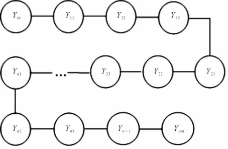
In order to demonstrate our algorithm, we use the attack graph of Figure 6 in each node of which a fraction of the attack takes place. In the following, we explain the op-erations that are accomplished in each node of the graph of Figure 6.
In node in, all possible keys are generated the proc-
ess of which was explained in Section 4.1. In node 11,
all possible keys that were generated in in are bitwise
XORed with the given plaintext using AIR system of Section 4.2 that is guided by splicing rules of Equations
(8)-(28). Then, the generated strings are forwarded to
S-boxes 1 4 of Figure 3 and in node , S-
boxes are applied in parallel to the output of node 11 in
accordance with splicing relations of Section (4.3). In 13
the generated strings are permuted in a fashion dictated by the cipher instructions according to the splicing rela- tions of Equations (59) and (62). The process of consecu- tive mixing with subkey and applying substitution and permutation operations go on in an iterated fashion in the next nodes such that in node n1, n2 and Yn3 mixing
with the subkey, the round substitution and the round permutation take place, respectively, and in
1
n
Y
Y
, ,
S S Y12
Y Y
Y Y
th
n nth
th
n Y
Y
these gained strings are XORed with corresponding
bits of the n1st subkey and eventually, in node Yout
the generated bits are compared with the given ciphertext and we can find the key of the cipher if they are equal.
6. Performance Evaluation of the Proposed
Scheme
Considering that the operations of each node take place concurrently for all strings that exist in that node, we can find the number of steps that takes to produce the key of the cipher. In node in by applying different combina-
tions of consecutive ciliate bio-operations to a single initial word which is applied in parallel and takes one step, we can produce all possible key of the cipher. In node 11 the XOR operation is applied between the
generated words of node and the plaintext and consider- ing that each XOR operation has a depth of three, four steps are required to evaluate XOR of two bits that pro- duces output of one. In node 12 two steps are required
to produce the resulting words. In node 13 two steps
should be accomplished to evaluate P-boxes. So, there will be the same steps for other nodes of i1 i2 i3 for
Y
Y
Y
Y
, ,
Y Y Y 2, 3, ,
i n
Y n2n2n4
. We further assume that there are n-rounds of substitutions and permutations. So, before the last
node, out, we need to do 1 4 opera-
[image:7.595.310.537.572.720.2]tions. The operations of the last node can be carried out as follows: Those bits that have been generated in node
out are XORed with the corresponding given ciphertext
bits which take 4-steps and then, the AND operation is applied to the results of XORs which takes one step. So,
altogether steps are mandatory to accomplish
our attack in which n is the number of SP rounds.
Y
8n10
, ,
S S
Assuming that we use our proposed scheme to break 16-Round DES cipher (n = 16) which has a Feistel struc- ture which can be assumed as a variant of SPN ciphers, using the analysis of Section 6, we need 138 steps of computation which gives it a superior performance over the proposed schemes of breaking DES using DNA computer [10] which requires 916 steps and membrane computing [11] which requires 278 steps of computations as well as breaking DES using network of evolutionary processors with parallel string rewriting rules (NEPPS) which requires 268 steps [12]. Furthermore, our proposed scheme, as opposed to [11] which needs exponential space, does not need exponential space and for a specific set of instructions of a given cipher, utilizes a constant number of splicing rules. The performance of our pro- posed scheme for cracking 16R-DES cipher in compare- son with the previously proposed schemes has been de- picted in Figure 7.
7. Simulation of the Proposed Attack
We conduct a computer simulation to test our proposed theoretical scheme to break a sample cipher based on the SPN of Figure 3 and in this section, first, we introduce the parameters of the sample cipher which we aim to cryptanalyze and then we explain the steps of our simu- lations and finally, we present the results of simulations.
7.1. Parameters of the Considered Cryptosystem
In what follows, we introduce the cryptosystem under consideration for simulation in this paper. As can be seen
in Figure 3, the input block size of our cryptosystem
equals to 16 bits and a certain operation takes place for n
rounds. Each round consists of substitution block, per- mutation and mixture of bits. This structure looks like the one that is used in DES and other modern block ciphers such as Rijndael [13]. The utilized blocks of the cipher can be defined as follows.
7.1.1. Substitution Block
In the cipher of Figure 3, we break the 16-bit block of input into four 4-bit blocks. Each sub-block constitutes an input to each S-box (a 4-to-4-bit S-box) that can be realized with a look-up table containing sixteen 4-bit values that can be defined with the integer numbers that are shown in the input bits of Table 1. The considered S-box is non-linear and the output bits of each S-box cannot be written as a linear combination of the inputs bits. Furthermore, it is assumed that all substitution
boxes of 1 4 are equivalent. Our considered sub-
stitution box for the cipher is shown in Table 1.
7.1.2. Permutation Block
The considered permutation schedule for the cipher of
Figure 3 is shown in Table 2. Numbers of this table
show the position of the bits in the block such that 1 shows the leftmost bit and 16 is the rightmost bit of the input block.
7.1.3. Mixing with Subkey
We define the operation of mixture with the key to be simply equal to applying the XOR gate between round key bits and the input block to the round.
In what follows, we design different sub-systems nec- essary for implementation of our proposed theoretical attack to the cipher.
Considering the above parameters in the cipher of
Figure 7. Graph of comparison for performance evaluation.
Table 1. Look-up table for the considered S-box.
Input 0 1 2 3 4 5 6 7
Output E 4 D 1 2 F B 8
Input 8 9 10 11 12 13 14 15
Output 3 A 6 C 5 9 0 7
Table 2. Bit permutation schedule of Figure 3.
Input 0 1 2 3 4 5 6 7
Output 1 5 9 13 2 6 10 14
Input 8 9 10 11 12 13 14 15
Output 3 7 11 15 4 8 12 16
Figure 3 and using splicing rules derived in Section 4, we simulate the proposed attack on the cipher.
We utilize Turing Machine Simulator software [14] to simulate our proposed attack on the cipher. For this rea- son, based on the splicing rules of Section 4, we write an initial program to simulate the main blocks of cryptana- lysis according to the cipher parameters (such as genera- tion of all keys, doing XOR, S-boxes and P-boxes). We write appropriate programs for each block to do compu- tations on the words written on the tape of the Turing machine which simulate the AIR systems designed in Sections 4.1-4.4. Then we combine all the written pro-grams based on the graph of Figure 4. In our simu- la-tion, we consider the following assumptions: we as- sume the number of rounds of the cipher equal to 1. Therefore we have one subkey string which is same as the main key and has a length of 16 bits. We further as-sume that the plaintext equals to “0000000000000000” and also the ciphertext is assumed to be “01011110011 00110”. Now, based on the our designed AIR system, we write the applied algorithm for cryptanalysis as follows.
Initially, by applying different splicing rules on an ini- tial sequence, we can produce all possible combinations of the key on the tape and then we put these strings on different segments of the tape with a certain distance from each other. Then, according to the splicing rules of Equations (8)-(28) we apply bitwise XOR operation be- tween key bits of each key and the corresponding plain- text bits and their output is placed in another place on the tape. Then, by using splicing rules of Equations (35)-(50) and (56), we apply the substitution boxes of Table 1 to the derived words in a parallel fashion and the resultant words are rewritten on the same words. Then, P-box of
Table 2 is applied in to the derived words in a parallel
manner which utilizes the splicing rules of Equations (59) and (62) and we rewrite them on the previously derived words. Then, we apply the logical XOR operation be- tween bits of the resultant words of this stage and the key bits which had been mixed with the resultant sequence of the previous steps (which have known location on the tape) and therefore, we can get to the enciphered mes- sage. Now, in accordance with the proposed operations in the last node of the graph of Figure 4, in this node, the achieved strings must be compared with the predefined ciphertext and if all the corresponding bits were equal, the used key is known as the cipher key.
We wrote appropriate programs to accomplish the abovementioned instructions and ultimately, we suc- cessfully derived the secret key equal to “0001001000 110100” which was predicted.
It is noteworthy that breaking the cipher of “Figure 3” with more rounds can be done in the same way. But for the sake of demonstration of our algorithm and also the problem of taking a long time for execution of the pro-
gram we tested it on the cipher with 1 round of opera- tions.
The codes shown in Appendix 1 are our specifically written programs to simulate Turing machines related to different building blocks necessary for the cryptanalysis procedure as demonstrated in Section 4 which are appro- priate for execution on the Turing Machine Simulator software [14].
Note that all the written programs halt and generate appropriate output strings in a finite number of iterations The results of execution of codes of Appendix 1 for the considered cipher, defined in Section 7.1, are shown in
Tables 3-6.
8. Conclusion
In this paper, we proposed a language-theoretic notion to break SPN class of block ciphers which is based on the gene assembly process that naturally occurs in ciliated protozoa during the procedure of converting scrambled MIC gene to MAC gene. Our scheme utilizes the AIR system which includes two modified versions of in- tramolecular ciliate bio-operations delp and trlp q, which
renders it the computational flavor of Turing machine. Assuming that we use our proposed scheme to break 16-Round DES cipher (n = 16) which has a Feistel struc-ture which can be assumed as a variant of SPN ciphers, using the analysis of Section 6, we need 138 steps of computation which gives it a superior performance over the proposed schemes of breaking DES using DNA computer [13] which requires 916 steps and membrane
Table 3. Results of simulation of S-boxes.
Number of parallel
operations Initial state Final state
Number of iterations
16 A0 HALT 80
Table 4. Results of simulation of P-boxes.
Number of parallel
operations Initial state Final state
Number of iterations
1 A0 HALT 17
Table 5. Results of simulation of mixing with subkey.
Number of parallel
operations Initial state Final state
Number of iterations
16 R2 HALT 12
Table 6. All operations of attack on the cipher.
Number of parallel
operations Initial state Final state
Number of iterations
Copyright © 2012 SciRes. IJCNS
computing [14] which requires 278 steps of computations as well as breaking DES using network of evolutionary processors with parallel string rewriting rules (NEPPS) which requires 268 steps [15]. Furthermore, our proposed scheme, as opposed to [14] which needs exponential space, does not need exponential space and for a specific set of instructions of a given cipher, utilizes a constant number of splicing rules. Finding nature-inspired com- putational models like L-systems or modified versions of P-systems or our utilized model, seem to be promising in developing efficient computational models which simu- late universal Turing machines and for future works, other computational problems can be suggested to be solved using these models.
REFERENCES
[1] L. M. Adleman, “Molecular Computation of Solutions to Combinatorial Problems,” Science, Vol. 266, No. 5187, 1994, pp. 1021-1024. doi:10.1126/science.7973651 [2] L. Kari and L. F. Landweber, “Computational Power of
Gene Rearrangement,” In: V. E. Winfree and D. K. Gif- ford, Eds., Proceedings of DNA Bases Computers, Ame- rican Mathematical Society, 1999, pp. 207-216.
[3] L. F. Landweber and L. Kari, “The Evolution of Cellular Computing: Nature’s Solution to a Computational Prob-lem,” Proceedings of the 4th DIMACS Meeting on DNA- Based Computers, Philadelphia, 15-19 June 1998, pp. 3- 15.
[4] R. Lipton, “Using DNA to Solve NP-Complete Prob-lems,” Science, Vol. 268, 1995, pp. 542-545.
doi:10.1126/science.7725098
[5] L. M. Adleman, P. W. K. Rothemund, S. Roweis and E. Winfree, “On Applying Molecular Computation to the Data Encryption Standard,” Proceedings of 2nd Annual Meeting on DNA Based Computers, DIMACS Workshop, Princeton University, Princeton, 10-12 June 1996, pp.
28-48.
[6] D. R. Stinson, “Cryptography: Theory and Practice,” CRC Press, Boca Raton, 2002.
[7] T. Head, “Formal Language Theory and DNA: An Ana- lysis of the Generative Capacity of Specific Recombinant Behaviors,” Bulletin of Mathematical Biology, Vol. 49, No. 6, 1987, pp. 737-759.
[8] T.-O. Ishdorj and I. Petre, “Gene Assembly Models and Boolean Circuits,” International Journal of Foundations of Computer Science, Vol. 19, No. 5, 2008, pp. 1133- 1145. doi:10.1142/S0129054108006182
[9] T.-O. Ishdorj, I. Petre and V. Rogojin, “Computational Power of Intramolecular Gene Assembly,” International Journal of Foundations of Computer Science, Vol. 18, No. 5, 2007, pp. 1123-1136.
doi:10.1142/S0129054107005169
[10] W. Stallings, “Cryptography and Network Security Prin-ciples and Practices,” 4th Edition, Prentice Hall, Upper Saddle River, 2005, pp. 134-173.
[11] http://www3.wittenberg.edu/bshelburne/Turing.htm [12] J. Castellanos, C. Martin-Vide, V. Mitrana and J.
Sem-pere, “Networks of Evolutionary Processors,” Acta In-formatica, Vol. 39, No. 6-7, 2003, pp. 517-529.
[13] D. Boneh, C. Dunworth and R. Lipton, “Breaking DES Using a Molecular Computer,” In: R. J. Lipton and E. B. Baum, Eds., DNA Based Computers: Proceedings of a DIMACS Workshop, Princeton, 10-12 June 1996, pp. 37-66.
[14] S. N. Krishna and R. Rama, “Breaking DES Using P System,” Theoretical Computer Science, Vol. 299, No. 1-3, 2003, pp. 495-508.
doi:10.1016/S0304-3975(02)00531-5
[15] A. Choudhary and K. Krithivasan, “Breaking DES Using Networks of Evolutionary Processors with Parallel String Rewriting Rules,” International Journal of Computer Mathematics, Vol. 86, No. 4, 2009, pp. 567-576.
Appendix 1: Program Codes for Simulation
of the Proposed AIR Systems
In this section, the code lines written for simulation of the proposed AIR systems for each building block of the attack are shown. Note that the programs have been written to be suitable for the Turing simulator software that was used for our simulations. R and L in the written programs demonstrate directions of right and left, re- spectively, of head of the considered Turing machines on the tape.
Code Lines for Simulation of S-Boxes Using AIR Systems
(A0, 0, 1, B0, R) (B0, 0, 1, C0, R) (C0, 0, 1, D0, R) (D0, 0, 0, E0, R) (E0, , , E0, R) (E0, 0, 0, A1, R) (A1, 0, 1, B1, R) (B1, 0, 0, C1, R) (C1, 1, 0, D1, R) (D1, , , D1, R) (D1, 0, 1, A2, R) (A2, 0, 1, B2, R) (B2, 1, 0, C2, R) (C2, 0, 1, D2, R) (D2, , , D2, R) (D2, 0, 0, A3, R) (A3, 0, 0, B3, R) (B3, 1, 0, C3, R) (C3, 1, 1, D3, R) (D3, , , D3, R) (D3, 0, 0, A4, R) (A4, 1, 0, B4, R) (B4, 0, 1, C4, R) (C4, 0, 0, D4, R) (D4, , , D4, R) (D4, 0, 1, A5, R) (A5, 1, 1, B5, R) (B5, 0, 1, C5, R) (C5, 1, 1, D5, R) (D5, , , D5, R) (D5, 0, 1, A6, R) (A6, 1, 0, B6, R) (B6, 1, 1, C6, R) (C6, 0, 1, D6, R) (D6, , , D6, R) (D6, 0, 1, A7, R) (A7, 1, 0, B7, R) (B7, 1, 0, C7, R) (C7, 1, 0, D7, R) (D7, , , D7, R) (D7, 1, 0, A8, R) (A8, 0, 0, B8, R) (B8, 0, 1, C8, R) (C8, 0, 1, D8, R) (D8, , , D8, R) (D8, 1, 1, A9, R) (A9, 0, 0, B9, R) (B9, 0, 1, C9, R) (C9, 1, 0, D9, R) (D9, , , D9, R) (D9, 1, 0, F0, R) (F0, 0, 1, G0, R)
(G0, 1, 1, H0, R) (H0, 0, 0, I0, R) (I0, , , I0, R) (I0, 1, 1, F1, R) (F1, 0, 1, G1, R) (G1, 1, 0, H1, R) (H1, 1, 0, I1, R) (I1, , , I1, R) (I1, 1, 0, F2, R) (F2, 1, 1, G2, R) (G2, 0, 0, H2, R) (H2, 0, 1, I2, R) (I2, , , I2, R) (I2, 1, 1, F3, R) (F3, 1, 0, G3, R) (G3, 0, 0, H3, R) (H3, 1, 1, I3, R) (I3, , , I3, R) (I3, 1, 0, F4, R) (F4, 1, 0, G4, R) (G4, 1, 0, H4, R) (H4, 0, 0, I4, R) (I4, , , I4, R) (I4, 1, 0, F5, R) (F5, 1, 1, G5, R) (G5, 1, 1, H5, R) (H5, 1, 1, I5, R) (I5, , , I5, R) (I5, , , Z, L)
Code Lines for Simulation of P-Boxes Using AIR Systems
(A0, a, a, B0, R) (B0, b, e, C0, R) (C0, c, i, D0, R) (D0, d, m, E0, R) (E0, e, b, A1, R) (A1, f, f, B1, R) (B1, g, j, C1, R) (C1, h, n, D1, R) (D1, i, c, A2, R) (A2, j, g, B2, R) (B2, k, k, C2, R) (C2, l, o, D2, R) (D2, m, d, A3, R) (A3, n, h, B3, R) (B3, o, l, C3, R) (C3, p, p, D3, R) (D3, , , D3, R) (D3, , , Z, L)
Code Lines for Simulation of XOR Using AIR Systems
(R2, 1, 1, R2, R) (R2, +, +, R2, R) (R2, 0, 0, R2, R) (R2, 1, 1, R2, R) (R2, 0, 0, R2, R) (R2, 1, 1, R2, R) (R2, 0, 0, R2, R) (R2, , , L0, L) (L0, 1, 0, L1, L) (L0, 0, 1, L0, L) (L0, +, , R4, R) (R4, 1, , R4, R) (R4, , , Z, R) (Z, , , Z, L)