PROCEEDINGS OF SPIE
SPIEDigitalLibrary.org/conference-proceedings-of-spie
A solid state 94 GHz FMCW Doppler
radar demonstrator for cloud profiling
Duncan A. Robertson, Robert I. Hunter
A solid-state 94 GHz FMCW Doppler radar demonstrator
for cloud profiling
Duncan A. Robertson*
1& Robert I. Hunter
11
University of St Andrews, SUPA School of Physics & Astronomy,
St Andrews, Fife KY16 9SS, Scotland
ABSTRACT
We present the design and characterization of a ground-based, zenith-pointing, 94 GHz FMCW Doppler radar demonstrator for cloud profiling. The radar uses an all solid-state and relatively simple homodyne architecture and two, low sidelobe 0.5 m diameter Fresnel zone plate antennas to reduce system costs. The low-phase noise, coherent radar employs a direct digital synthesis (DDS) chip for highly linear chirp generation. The design will be able to leverage ongoing future improvements in mm-wave low noise and power amplifier technology to maximize sensitivity. Once the radar is installed in a rooftop location, the processor will perform real-time range-Doppler measurements with averaging, to yield target velocity spectra as a function of altitude.
Keywords: Radar, FMCW Doppler, millimeter wave, coherent, cloud profiling, Fresnel zone plate, DDS.
1.
INTRODUCTION
Clouds play a very significant role in the energy balance of the Earth’s atmosphere and yet they are still relatively poorly understood. Atmospheric models require more and better data on clouds in order to enhance their accuracy. Over the past few decades, millimeter wave radars have become the preferred instrument to probe the structure of clouds and fog in the atmosphere due to their relatively high sensitivity to small hydrometeors (water droplets and ice particles)1. Most cloud radars operate at 35 or 94 GHz and are ground-based with zenith pointing antennas. Increasingly, scanning radars are being developed to allow monitoring of the cloud structure over a wider spatial volume. A few airborne cloud radars have been developed and currently there is one satellite borne cloud radar, CloudSat.
The majority of cloud radars are of a high power pulsed design exploiting vacuum tube amplifiers, typically the extended interaction klystron amplifier (EIKA). These amplifiers are capable of delivering kW of peak power and hundreds of watts of average power which is advantageous when measuring low reflectivity tenuous targets at long range. However, EIKAs are expensive, relatively large and heavy, and require cooling.
Cloud radars use large diameter, very narrow beamwidth antennas to maximize link gain. Typically, Cassegrain antennas are used but these are also expensive in large diameters at millimeter wavelengths. Additionally, their sidelobe levels are fairly modest, typically only -18 to -20 dB.
Consequently, high power pulsed cloud radars are usually quite large and very expensive instruments which has limited their deployment worldwide. However, meteorologists desire more widespread cloud monitoring to improve climate models and numerical weather prediction.
To address this cost barrier, several groups have been developing low power solid state cloud radars which use frequency modulated continuous wave (FMCW) modulation instead of pulsed operation2, 3, 4, 5, 6. In order to achieve sufficiently high transmit-receive isolation in an FMCW cloud radar it is conventional to use two antennas, which can be a significant contribution to the system cost.
In this paper we present a ground-based, zenith pointing, 94 GHz FMCW Doppler cloud radar technology demonstrator which achieves high performance yet with a lost cost solid-state architecture.
2.
SYSTEM OVERVIEW
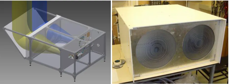
[image:3.612.74.540.170.342.2]The 94 GHz FMCW Doppler cloud profiling radar demonstrator is derived from an existing pulsed coherent radar7. The signal architecture has been modified from heterodyne pulsed to homodyne FMCW and utilizes separate horn-fed Fresnel zone plate (FZP) lens antennas for transmit and receive. The antenna beams point horizontally and are deflected to the zenith by a lightweight flat mirror made of aluminum honeycomb panel angled at 45°. The hardware is mounted in a framework of extruded aluminum profiles and covered with white UPVC foam panels for environmental protection - Figure 1.
Figure 1. CAD model of 94 GHz FMCW cloud profiling radar (left). Enclosure panels are shown as transparent to reveal internal features. Photo of cloud radar in lab with 45° mirror removed (right).
The radar is powered by a single 18 Vdc power supply and all internal components are fed via voltage regulators for low noise. Transmit and receive components are mounted on aluminum plates which provides heatsinking and are supported by the frame. External connections are made via through-bulkhead connectors. Control of the radar is provided by custom C code running on a high specification PC which also houses the analog-to-digital converter that samples the radar output. The radar is mounted outdoors on the roof of a building whilst the power supply and PC are located adjacently, indoors. The PC and power supply are connected to the radar by a 5 m long umbilical cable which passes through a cable duct in the wall of the building.
3.
RF/MICROWAVE DESIGN
BPF
CLK
x6
÷ 180
15.26 GHz 2400 MHz
10 MHz PLCRO PLDRO
13.33 MHz
15.66 GHz 94.0 GHz
x6 Baseband 400 MHz 94.0 GHz LNA Coax Det 15 GHz Monitor WG Det 94 GHz Monitor +25 dBm DDS ÷ 2048 A D C TRIG 6510 Hz LPF OCXO
5.3 dB NF
[image:4.612.92.521.76.304.2]Tx On/Off
Figure 2. Simplified circuit diagram of 94 GHz cloud radar transceiver.
Coherent operation is ensured by two design aspects:-
1. The 15.26 GHz and 2.4 GHz signals are phase locked to a 10 MHz crystal oscillator.
2. The ADC sampling clock of 13.33 MHz and the chirp repetition frequency (CRF) of 6510 Hz used to trigger the ADC sampling and the DDS chirp generation are derived by division from the 2.4 GHz oscillator. The CRF provides a maximum unambiguous Doppler velocity of ±5.19 ms-1 which is appropriate for cloud particles. Velocity sensitivity in a Doppler radar is governed by signal phase noise so care was taken when selecting the various oscillators employed in the radar. The 15.26 GHz STALO is a phase-locked dielectric resonator oscillator (PLDRO) and the 2.4 GHz source is a phase-locked cavity resonator oscillator (PLCRO) and both are locked to an ovenized crystal oscillator (OCXO) at 10 MHz. The single sideband phase noise profiles of these three oscillators are shown in Figure 3, taken from the manufacturers’ data.
Figure 3. Single sideband phase noise profiles of key oscillators used in the system, from manufacturers’ data.
-170
-160
-150
-140
-130
-120
-110
-100
-90
-80
-70
-60
100
1000
10000
100000
1000000
SS
B
Phas
e
Nois
e
[dB
m/
Hz
]
Offset frequency [Hz]
[image:4.612.128.485.465.679.2]E
m -o
+.,
C
a
3025
20
15
10
5
0
---30 -25
4****
**
..
-20 -15 -10 -5 0 5 10
Pin (dBm)
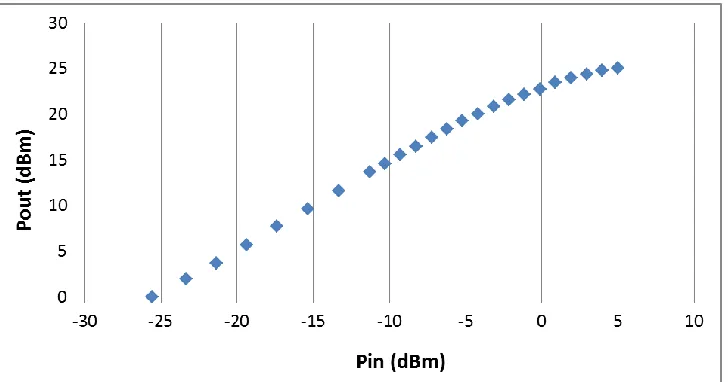
[image:5.612.126.490.150.341.2]The transmit PA was characterized for gain versus frequency and compression transfer characteristic at the center frequency. The small signal gain at 94 GHz was measured as 25 dB. Variation with frequency was <0.5 dB over a 1 GHz bandwidth and this is relatively unimportant considering the chirp bandwidth will be very small (few MHz). The compression transfer characteristic at 94 GHz is given in Figure 4 and shows the saturated output power is +25 dBm (0.32 W) for an input of +5 dBm. In the radar circuit the input signal level from the driving multiplier was adjusted to achieve saturation of the power amplifier.
Figure 4. Transmit power amplifier compression transfer characteristic measured at 94 GHz.
The receiver front end uses an LNA ahead of the 94 GHz fundamental balanced mixer to offer high sensitivity. The receiver noise figure was measured using the Y-factor method and found to be 5.3 dB (720 K noise temperature). This includes loss contributions ahead of the LNA due to the feedhorn and protective window over the horn aperture and is thus consistent with the manufacturer’s value for the LNA noise figure of 4.7 dB.
The combination of relatively high transmit power and low receiver noise figure provide the radar with a high sensitivity which is necessary for cloud profiling given the low reflectivity of the target. As the radar is intended to be a demonstrator of the FMCW Doppler architecture it was constructed from an existing radar and components available in the laboratory. It would be relatively straightforward to exploit ongoing advances in solid-state PA and LNA technology (e.g. GaN and GaAs / InP respectively) to achieve enhanced sensitivity as new devices become more widely available and more affordable. Realistic values of 2 W transmit power and 4 dB noise figure are now commercially available.
4.
ANTENNAS
Ground-based FMCW cloud profiling radars typically use zenith pointing antennas of high gain / narrow beamwidth in pairs to achieve sufficient transmit-receive isolation; at 94 GHz these would likely be 0.5 to 1.0 m in diameter. The most common type of high gain antenna at 94 GHz is the Cassegrain but these are very expensive in such large diameters and often have fairly modest sidelobe performance of only -18 to -20 dB. However, they do have the advantage of having a short focal distance, or F-number, for their diameter. In our case we did not have a particular space constraint so to realize a pair of low-cost 0.5 m diameter antennas we selected two horn-fed Fresnel zone plate (FZP) lens antennas. The feedhorns on transit and receive are 20 dBi corrugated horns with a sine-squared-parallel internal profile whose beamwaist is at the aperture8. As the radar will be used outdoors and to prevent the ingress of moisture or insects, the horn apertures are covered with Rexolite discs of matched thickness. These windows present low reflection and negligible loss at 94 GHz.
D
D
D
D
0
I ! I
Design
Meas. E plane
-Meas. H -plane
f
-1-2
ill-",
a
c -3
o
a
o
cu
cc
-4
-50
60
e.
ltv
I-4 -3.5 -3 -2.5 -2 -1.5 -1 -0.5 0 0.5 Angle [deg]
1.5 2 2 5 3 3.5 4
manufacturing. Whilst polycarbonate is intrinsically lossier than common lens materials such as HDPE or Rexolite, the realized loss is very low due to the small thickness of the zone plate. Full details of these FZPs has been previously published7.
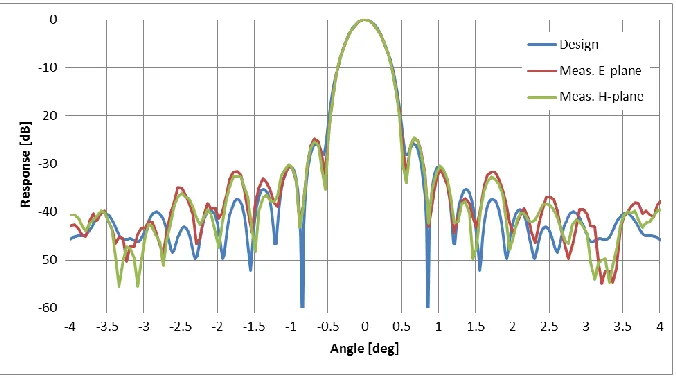
[image:6.612.138.476.179.368.2]The measured far-field patterns of the FZPs are shown in Figure 5 along with the design curve. The agreement is excellent. The mainlobe is very symmetrical with measured 3 dB beamwidths of 0.43° in both E- and H-planes and a peak sidelobe level of -25 dB. The measured gain is close to the predicted value of 52 dBi within experimental error (with a simulated aperture efficiency of 79%). When used in the radar, these antennas will yield a two-way beamwidth of 0.30° and sidelobe level of -50 dB.
Figure 5. Measured E- and H-plane far field patterns for 0.5 m diameter FZP at 94 GHz versus design.
These results demonstrate that millimeter wave large aperture Fresnel zone plate antennas can offer higher performance than Cassegrains of a similar size, for a fraction of the cost, albeit occupying a greater volume. Note that shorter F-number and hence more compact WZP designs are feasible but we made the decision to base our design on the availability of an existing feedhorn. In addition, compared to a conventional curved-surface lens, the WZP is much lighter and simpler to machine.
5.
PROCESSOR
The radar is controlled by a high specification PC (DELL Precision 3620, Intel Xeon E3-1245 v3 processor, 3.5 GHz clock, 16 GB RAM, 256 GB SSD) running the Windows 7 64-bit operating system. Control code is written in C using the National Instruments LabWindows/CVI programming environment. Radar control is achieved over USB with the customized DDS eval board and an NI USB-6000 Multifunction DAQ unit mounted inside the radar. Control functions include:-
1. DDS chirp programming 2. Power detector monitoring 3. Transmit switch operation
4. Temperature monitoring (PA temp., electronic enclosure temp., external temp.)
-6510Hz CRF -1s average
15 14 13 12
11
10 9 8
7
6
5
4
3
2
1
o
-50 -45 -40 -35 -30 -25 -20 -15 -10
Minimum Detectable Reflectivity [dBZ]
-5 0
The data processing, which is still under development, will perform various functions. Principally, FMCW Doppler processing will be performed over a coherent processing interval which can be chosen according to the Doppler resolution desired, traded-off against temporal resolution. This will yield the Doppler velocity spectrum as a function of altitude. Additionally, non-coherent averaging will be performed to reduce noise and typically averaging times for cloud radar signals are a few seconds – again this is a trade-off between temporal resolution and maximizing sensitivity.
6.
SYSTEM CHARACTERISATION & PERFORMANCE
The overall receive gain of the radar is 50 dB arising from the LNA (27.5 dB), mixer (-7 dB) and IF amplifier (29.5 dB). With the receiver noise figure of 5.3 dB and FFT bin width of 6510 Hz, this yields a noise power per FFT bin of -77.5 dBm/bin. This is well above the measured ADC noise floor of -90 dBm/bin for the ADC input range of ±1V. The maximum signal level for this ADC input range is +10 dBm which slightly exceeds the 1 dB compression point of the IF amplifier (+8 dBm). However, in this application, maximizing sensitivity to small signals is more important than large signal handling.
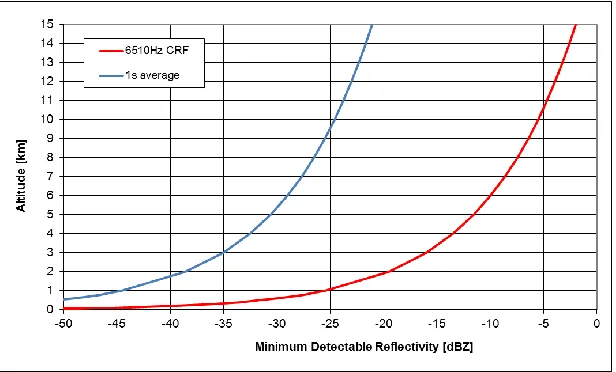
[image:7.612.121.489.285.431.2]It is common practice to assess the system sensitivity of cloud radars using the minimum detectable reflectivity (dBZ) as a function of altitude5. The parameters of the radar required to calculate the sensitivity are given in Table 1.
Table 1. Radar parameter used to calculate minimum detectable reflectivity.
Parameter Value Unit
Transmit Power 25 dBm
Antenna Gain 52 dBi
Antenna Beamwidth 0.43 °
Range Bin Width 10 m
Wavelength 3.19 mm
Noise Figure 5.3 dB
Chirp Repetition Frequency 6510 Hz
The minimum detectable reflectivity as a function of altitude is shown in Figure 6. The ‘6510 Hz CRF’ curve is for a single shot measurement in one chirp duration (153 µs). The ‘1s average’ curve is for non-coherent integration of 6510 chirps assuming a √𝑁 improvement. These curves indicate that the radar, once deployed in its rooftop location, will be capable of measuring clouds and fog with the expected levels of reflectivity, certainly to altitudes on many kilometers.
[image:7.612.155.463.502.688.2]7.
CONCLUSIONS
We have presented the design and characterization of a ground-based, zenith-pointing, 94 GHz FMCW Doppler radar demonstrator for cloud profiling. The radar uses an all solid-state and relatively simple homodyne architecture with twin 0.5 m diameter Fresnel zone plate antennas to reduce system costs. The measured performance of these low cost FZPs agrees closely with the design predictions and exceeds that obtainable with a Cassegrain of equivalent size.
The low-phase noise, coherent radar employs a direct digital synthesis (DDS) chip for highly linear chirp generation. Signal processing is undertaken on a PC which will perform real-time range-Doppler measurements with averaging, to yield target velocity spectra as a function of altitude. The design will be able to leverage ongoing future improvements in mm-wave low noise and power amplifier technology to maximize sensitivity against low reflectivity atmospheric targets. The predicted minimum detectable reflectivity measureable with the radar meets the requirements for cloud profiling. Data collection will begin shortly once the radar is installed in a roof top location and the signal processing is completed. We anticipate that the high performance achievable with this lower cost architecture could lead to wider deployment of CPRs for operational atmospheric monitoring.
8.
ACKNOWLEDGEMENTS
The authors thank The University of St Andrews for funding this work via the EPSRC Impact Acceleration Account.
REFERENCES
[1] Kollias, P., E.E. Clothiaux, M.A. Miller, B.A. Albrecht, G.L. Stephens, and T.P. Ackerman, “Millimeter-Wavelength Radars: New Frontier in Atmospheric Cloud and Precipitation Research”. Bull. Amer. Meteor. Soc., 88, pp. 1608–1624, 2007.
[2] Huggard, P.G., Oldfield, M.L., Moyna, B.P., Ellison, B.N., Matheson, D.N., Bennett, A.J., Gaffard, C., Oakley, T, and Nash, T., “94 GHz FMCW cloud radar,” Proc. SPIE 7117, Millimetre Wave and Terahertz Sensors and Technology, 711704, 2008.
[3] Yamaguchi, Y. et al, “Sensitivity of FMCW 95GHz Cloud Radar for High Clouds”, Proc. Asia Pacific Microwave Conf., pp. 1841 – 1846, 2006, DOI: 10.1109/APMC.2006.4429767
[4] Delanoe, J. et al, “BASTA: A 95-GHz FMCW Doppler Radar for Cloud and Fog Studies”, Journal Atmos. Oceanic Technol., vol. 33, pp. 1023 – 1038, 2016, DOI: 10.1175/JTECH-D-15-0104.1
[5] Rubio-Cidre, G., Grajal, J., Garcia-Pino, A. and Rubiños, O., “Design and preliminary results of a ground-based cloud profiling radar at 94 GHz”, IEEE Radar Conference (RadarConf), pp. 1- 6, 2016, DOI: 10.1109/RADAR.2016.7485286
[6] Novel Product Line FMCW Cloud Radars, Radiometer Physics GmbH, http://www.radiometer-physics.de/download/PDF/Cloud%20Radar/RPG-FMCW-94-Brochure.pdf
[7] Robertson, D. A., Hunter, R. I. & Gallacher, T., “94 GHz pulsed coherent radar for high power amplifier evaluation”, Proc. SPIE 9829, Radar Sensor Technology XX, Apr. 2016, pp. 1-8.
[8] McKay, J., Robertson, D.A., Cruickshank, P.A.S., Hunter, R.I., Bolton, D.R., Wylde, R.J. and Smith, G.M., “Compact Wideband Corrugated Feedhorns With Ultra-Low Sidelobes for Very High Performance Antennas and Quasi-Optical Systems”, IEEE Trans. Antennas and Propagation, Vol. 61, No. 4, pp. 1714 – 1721, 2013. [9] Hristov, H., Fresnel zones in wireless links, zone plate lenses and antennas, Artech House, 2000.