Drilling Operation and Formation Damage
Hooman Fallah, Sara Sheydai
Department of Petroleum Engineering, Islamic Azad University, Firoozabad Branch, Firoozabad, Iran Email: [email protected]
Received March 26, 2013; revised April 28, 2013; accepted May 6, 2013
Copyright © 2013 Hooman Fallah, Sara Sheydai. This is an open access article distributed under the Creative Commons Attribution License, which permits unrestricted use, distribution, and reproduction in any medium, provided the original work is properly cited.
ABSTRACT
Transport of particle suspensions in oil reservoirs is an essential phenomenon in many oil industry processes. Solid and liquid particles dispersed in the drilling fluid (mud) are trapped by the rock (porous medium) and permeability decline takes place during drilling fluid invasion into reservoir resulting in formation damage. The formation damage due to mud filtration is explained by erosion of external filter cake. Nevertheless, the stabilization is observed in core floods, which demonstrates internal erosion. A new mathematical model for detachment of particles is based on mechanical equilibrium of a particle positioned on the internal cake or matrix surface in the pore space. In the current work the analytical solution obtained to mud filtration with one particle capture mechanism with damage stabilization. The cle torque equilibrium is determined by the dimensionless ratio between the drag and normal forces acting on the parti-cle. The maximum retention function of the dimensionless ratio closes system of governing equations for colloid trans-port through porous medium.
Keywords: Formation Damage; Drilling Mud; Classical Filtration; Maximum Retention Function External Filter Cake
1. Introduction
Formation damage is an undesirable operational and eco- nomic problem that can occur during the various phases of oil and gas recovery from subsurface reservoirs in-cluding production, drilling, hydraulic fracturing, and work-over operations. Formation damage assessment, con- trol, and remediation are among the most important is-sues to be resolved for efficient exploitation of hydro- carbon reservoirs [1].
Formation damage indicators include permeability impairment, skin, damage and decrease of well perform- ance. Flow of suspensions in rocks with particle capture and consequent permeability impairment is an essential phenomenon in many oil industry processes. Particle capture by rock and permeability decline takes place dur- ing drilling fluid invasion into reservoir resulting in for-mation damage. It also occurs during fines migration, mostly in reservoirs with low consolidated sands and heavy oil.
Diagnosis of formation damage allows choosing the right damage removal technology during seawater injec- tion to enhance the recovery factor of hydrocarbon res- ervoirs. The particle erosion was described by introduc- tion of a new particle storage capacity function which is equal to maximum retained concentration versus dimen- sionless flow velocity. The particle storage capacity
func-tion is a reological characteristic that closes system of governing equations.
Deep bed filtration of fines with capture and perme- ability damage takes place near to production wells, in drilling operation. The particles in drilling fluid are cap- tured by size exclusion (straining) or by different at- tachment mechanisms (electric forces, gravity segrega- tion and diffusion). The analytical solution for deep bed filtration shows that for the case of the vanishing filtra- tion function, the injectivity stabilizes when time tends to infinity.
The classical mathematical model for suspension flow in rocks consists of particle balance and capture kinetics equations [2]. It is assumed that the mean particle speed is equal to carrier water velocity.
External filter cake is the term used to describe the particles retained at the interface of porous medium. The retention of particles occurs due to different phenomena including size exclusion; i.e. at the wellbore (Barkman and Davidson 1972) [3]. An alternative mechanism for the development of an external filter cake is that of tran- sitioning from internal filtration to external filter cake buildup. An example of external filter cake build-up due to size exclusion is that associated with drilling. When drilling, the circulating mud is designed to prevent fluid leak-off with minimal internal filtration by forming ex- ternal filter cakes due to size exclusion. Such cakes are easier to remedy and stimulate, whereas internal filtration is more difficult to remedy.
2. Literature Review
Davison et al. [4] conducted experiments by following colloidal silica suspension through three types of core plugs taken from Berea, Noxie and Cleveland sandstones. Their results show that particles initially pass through the larger openings in the core and are stopped gradually by a combination of effects of sedimentation, direct inter- ception and surface deposition. The plugging of the core appears to be a combination of internal blockage of pores and cake buildup. They found that the larger particles initiate cake formation.
In most cases, the core itself was only partially plug- ged, but the experimental cake formed at the face of the core restricted the flow of the suspension. Davidson [4] conducted experiments on the flow of particles suspen- sions through porous media. A major finding of this work was that the velocity required to prevent particle deposition is reversely related to the particle size. How- ever, it is the first indication in the literature that there is a relationship between particle movement through porous media and linear flow velocity.
Todd et al. [5] conducted particle-plugging experi- ments on three different core materials. The result of these studies indicates that significant permeability im- pairment can be caused by inorganic solids, even in di- lute system.
Todd [6] used aluminum oxide particles in the size ranges 0 to 3, 4 to 6, and 8 to 1 microns. They found the following: 1) The overall damage is related to the mean pore-throat size; 2) The cores damaged with 0 to 3 micron suspensions exhibit damage throughout their entire length; and 3) As particle size increases, the damage is gradually shifted toward the injection end of the core.
When suspended particles in a carrier fluid are flowed through a porous medium, the operative plugging me- chanism depends on the characteristics of the particles, the characteristics of the formation and the nature of the interaction between the particles and the various reser-
voir materials.
The particle/pore size ratio is the most important parameter in the filtration process. It has been found that larger particle/pore size ratios tend to cause rapid, but shallow, damage.
Particle retention and formation damage accumulation take place according to the classical suspension filtration theory until the retention concentration reaches the cri- tical value defined by the torque balance, from now on the particles do not deposit any more.
3. Particle Mechanical Equilibrium and
Maximum Retention Concentration
Function
Particle capture by the rock takes place until the drog force moment, acting on the particle on the surface of the growing internal cake by moving water exceeds the at- tractive normal force moment.
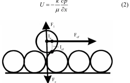
Particle capture and filling the space in a pore results in the porosity decrease and in increase of interstitial velocity of fluid in a pore, provided the same injection rates maintained. Consequently increases the drag force acting on a particle on the internal cake surface from moving fluid (Figure 1).
According to Jiao and Sharma [7] for particle equilib- rium on the cake surface as the equality torques for elec- tric and drag forces:
cf cf n n
F l F l (1) Here the normal force is a total of electric and lifting forces.
Drag force is the general expression for the drag force acting on a spherical particle in flow between two paral-lel plates. The lever arms for drag and normal force have the same order of magnitude. Their ratio is equal to 30.5 for the case of equal spherical particles (Figure 1).
Appendix A provides all the above-mentioned forces. The flow velocity and the pressure gradient are linked by the Darcy law. According the Darcy equation for fluid (Mud Filtrate) flow through porous media:
k p U
x
[image:2.595.330.541.572.707.2] (2)
Here we introduce the dimensionless parameter which is ratio between the drag force and the normal force:
3
Ua
0
e
n k F
(3)
As it follows from the torque balance and the velocity de
on concentration becomes a fun- ct
pendencies of drag and lifting forces, for each flow velocity there does not exist a maximum retained con- centration that correspond to equilibrium of torques act- ing on a single particle.
The maximum retenti
ion of the particle dislodging number, expressing the relationship between cr and ε:
30
,
cr cr
n
U a
k F
(4)
The higher is the velocity U, the higher is the numera- tor in the expression (4) for the erosion number , the higher is the lifting force and the lower is the deno ina- tor in (4). So the erosion number is a monotonically in- creasing function of U. The dependence (4) is called the storage capacity function.
m
Th ltra-
4. Basic Equation for Classical Filtration
Theory with Retained Particle Release
e particle capture rate is given by the classical fi tion theory [8] assuming that retention rate is propor- tional to particle flux cU, i.e.
:cr e t cU
(5)
Here the deposited concentration is significantly lower than the concentration of vacancies in the pore space which means that the filtration coefficient is con- stant.
The mathematical mass balance for suspended and re- tained particles during 1 d linear filtration is
c 0
c U
t x
(6)
The Darcy equation accounting for formation damage describes the flux and pressure distribution
1
k p
U
µ x
(7)
The derivations of dimensionless system along with in
Th for system
the under saturated case
itial and boundary data are presented in Appendix B.
5. Analytical Solution for Erosive Classical
Filtration with One Capture Mechanism
for Constant Rate Mud Invasion
e initial boundary value problem (B-6,7)
(B-2,5) allows for exact analytical solution. Below the
solution is derived.
This solution for S S cr is
well known [9]. Expressing suspension con ion from (B-3)
centrat
1
D S C
t
(8)
Substituting it into (B-2) and integrating in tD with
regards to initial condition (B-6), we obtain
D D
S S S
t x
(9)
From kinetics Equation (B-3) and boundary condition (B-7) we derive the following boundary condition for retained concentration:
0 : D
X St (10) The solution is obtained by meth
[9
od of characteristics ]. Both concentrations are zero ahead of the concentra- tion front xDtD:
: 0
D D
x t S C (11) Equation (9) in characteristic form is
1, ,
cr
cr D D
x S c
S C
t t t
(12)
That with boundary condition (10) leads to the solu- tio
n
exp exp
D D D
D
S t x x
C x
(13)
At the moment tcrScr , the retained concentration
at the inlet xD 0 reaches the critical value. Appears a
front xcr xcr
tD ont whi along S S cr . Further retention
behind the fr ch does not happen:
D, D
cr,
D, D
S x t S C x t 1 (14) Differentiate the condition of
si cr
S S along the ero- on front
tr D , D
crS x t t S (15) by tD:
0
cr
D D D
x
S S
t t x
(16)
Equation (16) contains three unknowns: both partial de
f S.
on
rivatives of S and velocity of the erosion front. Equation (9) also contains two partial derivatives o Let us derive the condition of particle flux continuity the erosion front xcr xcr
tD :
1
1
C D S D C D ScrD
As it follows from rate Equation (B-3), conc tration S is
en
on on t
Which leaves two possibilities: eith or C is co
e de
sion front, and the balance conditi he shock be- comes
CC
1D
0er D1
nt is l
ntinuous. Since velocity of erosion fro ess than unity, the suspended concentration is continuous. There- fore, C1 along the erosion front. It allows calculating the tim rivative of S:
D S
t
(17)
Equations (9), (16) and (17) from a linear system of three eqs. for three unknowns. The solution is
1 cr
,D D
S
x t
S S
(18)
d 1
d
cr
D cr x
t S 1 (19)
Finally, we obtain equation for erosion front:
0
cr cr
t S
, 1
1
D cr
cr cr cr D cr
cr
t S
x t S x S
S
(20)
Above expressions define the analytical model for in- je
ximu ta
perfectly m
6. Conclusion
filtrate during drilling operation and
ension mud model with stabilized retention co
with on
ssure drop measurement during core flood by parti- cl
REFERENCES
[1] F. Civan, “Re ge (Fundamentals,
us Medium Mod
ction of suspension with the constant rate accounting for retained particle dislodging by drag force.
Introduction of just one new parameter-ma m re- ined concentration- into a classical suspension filtration model allows for significant enrichment of the physics schema for suspension transport and retention.
The analytical model developed allows to
atch the experimental impedance curve and calculated from it three injectivity parameters- filtration and forma- tion damage coefficients, and also the maximum reten- tion concentration.
Near wellbore mud
the resulting formation damage are amongst the most im- portant problems involving the petroleum reservoir ex-ploitation.
The susp
ncentration is based on the assumption that for each flow velocity there does exist the maximum amount of retention particles that electric-molecular forces can keep. The dimensionless erosion number, which is ratio be-
tween the cross flow drag force and the total of normal forces, is proportional to flow velocity. The stabilization phenomenon is characterized by so called storage capa- city which is the maximum retention concentration ver-sus erosion number. The maximum retention function of the dimensionless ratio closes system of governing equa-tions for colloid transport through porous medium.
The analytical solution obtained to mud filtration e particle capture mechanism with damage stabiliza- tion.
Pre
e suspension allows for complete characterization of the filtration damage system, i.e., mud filtration and for- mation damage coefficients altogether with maximum retention concentration can be calculated.
servoir Formation Dama
Modeling, Assessment and Mitigation),” 2nd Edition, Gulf Professional Publishing, Houston, 2006.
[2] A. C. Payatakes, et al., “Application of Poro
els to the Study of Deep Bed Filtration,” The Cana-dian Journal of Chemical Engineering, Vol. 52, No. 6, 1974, pp. 722-731.doi:10.1002/cjce.5450520605
[3] J. H. Barkman and D. H. Davidson, “Measuring Water
al., “Review of Permeability Damage
of Depth of Forma-
nism of Cake Buildup Quality and Predicting Well Impairment,” Journal of Pe- troleum Technology, Vol. 24, No. 7, 1972, pp. 865-873. [4] E. C. Davison, “Particle Transport in Sandstone,” SPE
Annual Technical Conference and Exhibition, Denver, 12 October 1977.
[5] A. C. Todd, et
Stodies and Related North Sea Water Injection,” SPE In-ternational Symosium on Oilfield and Geothermal Che- mistry, Dallas, 22-24 January 1979.
[6] A. C. Todd, et al., “The Application
tion Damage Measurments in Predicted Water Injectivity Decline,” SPE Formation Damage Control Symposium, Bakersfield, 13-14 February 1984.
[7] D. Jiao and M. M. Sharma, “Mecha
in Crossflow Filtration of Colloidal Suspensions,” Jour- nal of Colloidal and Interfacial Science, Vol. 162, No. 2, 1994, pp. 454-462.doi:10.1006/jcis.1994.1060
[8] J. P. Herzig, D. M. Leclerc and P. Le Goff, “Flow of Suspensions through Porous Media,” Journal of Indus- trial and Engineering Chemistry, Vol. 65, No. 5, 1970, pp. 8-35.doi:10.1021/ie50725a003
Nomenclator
cf
F : Drag force
e
F : Lifting force g
F : Gravity force : Viscosity
И : Hamkar constant : Filtration coefficient : Effective porosity
c: Volumetric concentration of suspended particles with respect to the volume
: Volumetric concentration of retained particles with respect to the bulk volume
S
: Surface to surface separation 0
: Permittivity under vacuum
w
: Permittivity of the solute (water) 1
: Surface potentials of particles and collectors respec-tively
: Inverse Debye length
: Difference between the densities of the suspended particles (hematite) and the suspending fluid (water)
Appendix A. Forces Acting on the Captured
Particle on the Surface of Internal Cake on
the Pore Wall
Consider forces which act on the captured particle ( Fig-ure 1): darg force Fcf acting on the particle from by- passing viscous water; electric-molecular force Fe; lift-
ing force F1 and gravity Fg.
A general form of the crossflow drag force in Hele- Shaw flow in rectangular channel geometry with a single permeable wall is given as:
2 π cf a U F H h (A-1)
where is proportionality factor in the range [10, 60], is the viscosity, is the particle radius, cf is the average crossflow velocity at a given cross-section,
a u
H is the height of the channel, and h is the thickness of the cake at a given cross-section.
The electrostatic (a.k.a. surface or colloidal) force is directly proportional to the radius of the particles and is given by (10):
e e
F aA (A-2) where:
2 2 2 21 1 1 2 0 28 6 14 2 2π 1 S S S
e vdW EDL
r r S
vdW
S r S
EDL w
A A A
И A ę A ę ę
Here r is the characteristic retardation wavelength of interaction and is often assumed to be 100 nm20,
Иis the Hamkar constant of the interacting media, S is the surface to surface separation, 0 and w are the permittivity under vacuum and relative dielectric permit- tivity of the solute (water) respectively, 1 2
and
are the surface potentials of particles and collectors respec- tively and is the inverse Debye length.
It should be noted that at certain salinities and pH val- ues decreasing the surface to surface separation S
between one hematite particle and the other from infinity to zero yields two energy minima. The secondary mini- mum usually corresponds to a separation of >15 nm while the primary minimum corresponds to surface to surface separation of 4 nm. By considering only the forces acting along the axis parallel to the permeate force, a check can be made to see whether the particle has enough energy to overcome the activation energy and position itself within the primary minimum.
The general force of lifting force is given by:
3 3 3 cf L u F a H h (A-3)
where was given as 89.5 by Kang et al. (11). The gravity force is given by:
3 4π
3
g
a
F g (A-4)
where is the difference between the densities of the suspended particles (hematite) and the suspending fluid (water). The normal force in Figure 1 is a total of elec- tric molecular and lifting forces.
Appendix B. Basic Equations for Suspension
Transport with One Particle Capture
Mechanisms and Deposit Erosion
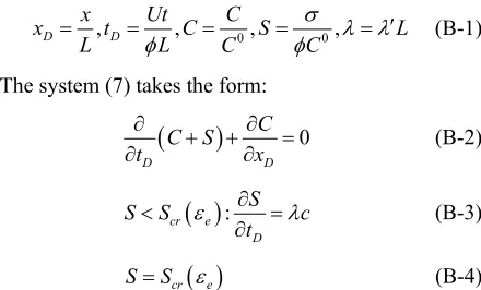
Let us introduce dimensionless length and time into the dimensionless system for classical filtration with particle dislodging (7):
0 0
, , , ,
D D
x Ut C
x t C S
L L C C L
(B-1)
The system (7) takes the form:
0D D C C S t x
(B-2)
: cr eD S
S S c
t
(B-3)
cr e
[image:5.595.318.538.573.706.2]
cr e
0D S
S S c
t
(B-5)
Initial condition for system (B-2,5) correspond to ab- sence of either suspended or deposited particles in the core before the suspension injection
,0
, 0
0C X S X (B-6)
Boundary condition corresponds to a given inlet con- centration