Joyce Namakoye
PERFORMANCE EVALUATION OF VOICE
HANDOVER BETWEEN LTE AND UMTS
A Research Report submitted to the Faculty of Engineering and the Built Environment,
University of the Witwatersrand, in partial fulfilment of the requirements for the degree
of Master of Science in Engineering
DECLARATION
I declare that this research report is my own unaided work. It is being submitted for the Degree of Master of Science to the University of the Witwatersrand, Johannesburg. It has not been submitted before for any degree or examination to any other University.
Candidate Signature :
Name : Joyce Namakoye
ABSTRACT
The main objective of seamless mobility is to enable mobile users to stay connected while roaming across heterogeneous networks. As cellular networks evolve from the third generation Universal Mobile Telecommunication System (UMTS) to the Long Term Evolution (LTE), a new Evolved Packet Core (EPC) will support heterogeneous radio access networks on the same platform. UMTS provides voice services in the circuit switched domain; while LTE operates in the packet switched domain. Cellular network operators thus face the challenge of providing voice services during initial deployment of LTE due to difficulty in mobility between the two domains. Seamless voice handover between packet switched LTE and the circuit switched UMTS network is therefore an important tool in solving this problem.
This report investigates the performance of inter-Radio Access Technology voice handover between LTE and UMTS. The schemes evaluated were Voice Call Continuity (VCC) for UMTS to LTE handover and Single Radio Voice Call Continuity (SRVCC) for LTE to UMTS handover. The performance evaluation was done using mathematical models and equations that were derived for the handover service interruption time. The resulting equations were simulated and the output was analysed and compared with the Third Generation Partnership Project (3GPP) specifications.
ACKNOWLEDGEMENT
I wish to express my sincere gratitude to my supervisor, Professor Rex Van Olst for his guidance and unwavering support. Thank you for being patient with many of my shortcomings and always being willing to help.
I also wish to convey my sincere thanks to members of the Center for Telecommunications Access and Services (CeTAS) at the University of the Witwatersrand, not only for their academic support but the financial assistance which enabled me to complete this work.
My special gratitude also goes to Mr. Kyungmin Kim of Yonsei University, South Korea as well as Mr. Ryan Van den Bergh of CeTAS and Mr. Giuseppe Piro of Telematics Labs for their advice on the subject matter of this research work.
I would like to especially thank Mr. Ryan Van den Berg, Mr. Aveer Ramnath, Mr. Ling Cheng, Mr. Jaco Versfeld, Mr. Kennedy Ifeh, Mr. Julius Popoola, Ms. Folasade Danhunsi, Mr. Mehroze Abdullah and all the members of CeTAS for the different roles they played in making this work come to fruition. Lastly but not least I would like to thank my family and friends whose faith, friendship and love gave me the courage to take on this challenge. Thank you for believing in me.
DEDICATION
To AlexABBREVIATIONS
3GPP Third Generation Partnership Project
BLER Block Error Rate
CQI Channel Quality Indicator
CS Circuit Switched
DTM Dual Transfer Mode
ENodeB (ENB) Evolved Node B
EPC/S Evolved Packet Core/System
E-UTRAN Evolved Universal Terrestrial Radio Access Network
GERAN GSM EDGE Access Network
HSPA High Speed Packet Access
IMS IP Multimedia System
Inter-RAT Inter Radio Access Technology
IP Internet Protocol
ITU International Telecommunications Union
LTE Long Term Evolution
MAC Media Access Control
MIMO Multiple Input Multiple Output
MME Mobility Management Entity
OFDMA Orthogonal Frequency Division Multiple Access
P-CCPCH Primary Common Control Physical Channel
PDCP Packet Data Control Protocol
PGW Packet Data Network Gateway
PS Packet Switched
RAB Radio Access Bearer
RAN Radio Access Network
RLC Radio Link Controller
RRC Radio Resource Control
RRM Radio Resource Management
RSRP Reference Symbols Received Power
SC-FDMA Single Carrier Frequency Division Multiple Access
SGW Serving Gateway
SRNC Serving Radio Network Controller
SR-VCC Single Radio Voice Call Continuity
UMTS Universal Mobile Telecommunications System
UTRAN Universal Terrestrial Radio Access Network
VoLGA Voice over LTE via Generic Access
WCDMA Wideband Code Division Multiple Access
Wi-Fi Wireless Fidelity
WiMAX Worldwide Interoperability for Microwave Access
LIST OF FIGURES
Figure 2.1: Summary of RAN evolution ... 14
Figure 3.1: UMTS Network Architecture ... 17
Figure 3.2: Spreading and De-spreading principal of DS-CDMA ... 20
Figure 3.3: UTRA Radio Interface Protocol ... 21
Figure 3.4: Radio Resource Management and Radio Resource Control functions ... 23
Figure 3.5: Basic Handover process ... 24
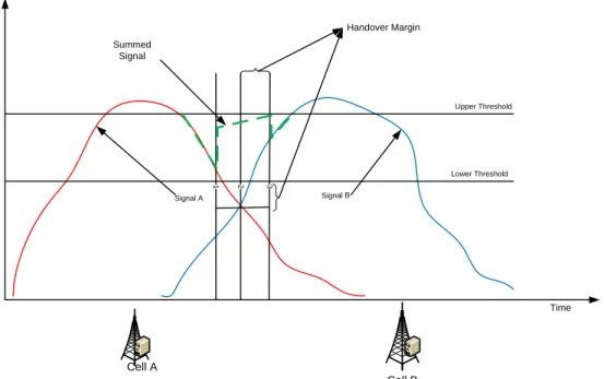
Figure 3.6: General principles of handover algorithms ... 27
Figure 3.7: Intra-frequency hard handover ... 29
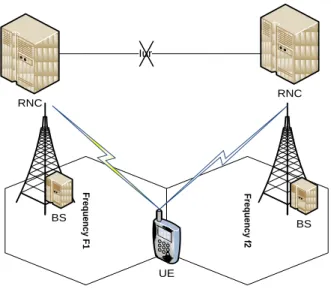
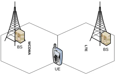
Figure 3.8: Inter-system hard handover ... 30
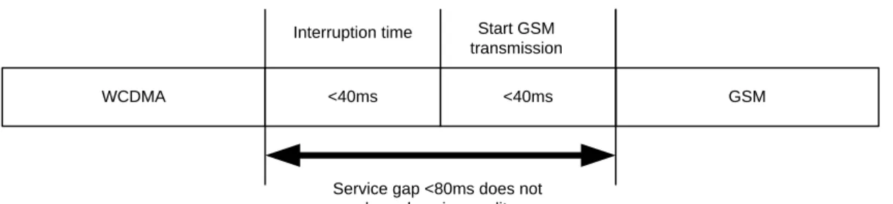
Figure 3.9: Service interruption time between GSM and WCDMA handover ... 31
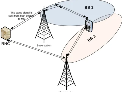
Figure 3.10: Intra-frequency soft handover ... 32
Figure 3.11: Softer handover ... 32
Figure 3.12: Closed loop power control in CDMA ... 33
Figure 3.13: Upgrade to HSPA then deploy LTE as islands in WCDMA/HSPA Sea ... 35
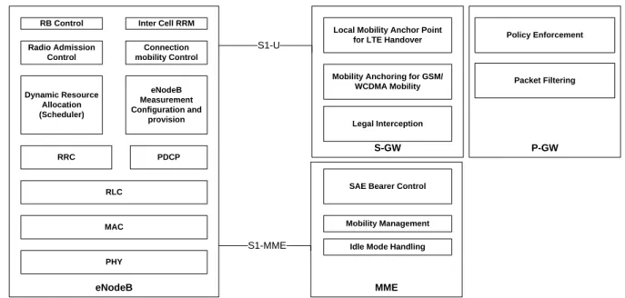
Figure 3.14: LTE/EPC Architecture ... 36
Figure 3.15: Functional split between the radio access and core network in LTE ... 37
Figure 3.16: LTE user plane protocol stack ... 38
Figure 3.17: WCDMA and LTE RRC protocol states ... 39
Figure 3.18: LTE Control-plane protocol stack ... 39
Figure 3.19: The EPC interworking IMS with other networks ... 41
Figure 3.20: Relationship between bearer and interface ... 42
Figure 3.21: X2 based handover without S-GW relocation ... 46
Figure 3.22: X2 based handover with change in S-GW... 47
Figure 3.23: S1-based handover... 47
Figure 3.24: EUTRAN to UTRAN handover at physical layer ... 49
Figure 3.25: E-UTRAN to UTRAN handover call flow summary ... 50
Figure 4.1: Voice over LTE via GAN ... 53
Figure 4.2: Mobile originated call flow in VoLGA ... 55
Figure 4.3: Evolved Packet System Architecture for CSFB ... 56
Figure 4.4: CSFB concept ... 57
Figure 4.5: CSFB MOC procedure [47] ... 58
Figure 4.6: SRVCC reference architecture ... 60
Figure 4.8: LTE to CS handover signal flow ... 62
Figure 4.9: VCC Reference architecture... 64
Figure 4.10: UMTS CS Call setup with IMS anchoring ... 65
Figure 4.11: UMTS to LTE handover signal flow... 66
Figure 6.1: Frame transfer in UTRAN with RLC ... 73
Figure 6.2: M/G/1 Model for Internet queuing ... 77
Figure 6.3: Entities involved in LTE Mobile Originated Call ... 78
Figure 6.4: LTE to UMTS service interruption ... 79
Figure 6.5: Call Setup for UMTS-CS with anchoring in IMS ... 80
Figure 6.6: UMTS to LTE VCC service interruption time ... 80
Figure 6.7: Model for Phase 1 simulation ... 81
Figure 6.8: Model for Phase 2 Simulation... 82
Figure 7.1: LTE to UMTS SRVCC service interruption time Vs BLER ... 85
Figure 7.2: LTE to UMTS SRVCC service Interruption time Vs BLER for varying propagation delay... 86
Figure 7.3: LTE to UMTS SRVCC Service Interruption versus Radio Propagation Delay ... 86
Figure 7.4: SRVCC Service interruption time under real-time network conditions ... 87
Figure 7.5: UMTS to LTE interruption time vs. BLER for various data rates ... 88
Figure 7.6 : Service Interruption time vs. BLER for UMTS to LTE handover ... 89
Figure 7.7: Service: Interruption Vs. Propagation delay ... 90
LIST OF TABLES
Table 2.1: Characteristics of the AMPS and NMT cellular systems [15] ... 9
Table 3.1: Main WCDMA Parameters [7] ... 19
Table 3.2: LTE and WCDMA physical layer comparison ... 40
Table 3.3: Example of label characteristics ... 43
Table 3.4: UMTS QoS classes and their parameters ... 44
Table 3.5: LTE QoS classes and their main parameters ... 44
Table 4.1: Comparison of feasibility voice handover techniques ... 67
Table 4.2: Comparison of SRVCC and CSFB ... 68
Table 6.1: Parameter list for RLC analysis ... 75
Table 6.2: Theoretical Service and Arrival rates of network nodes ... 76
LIST OF EQUATIONS
Equation 6.1: Delay under ideal conditions ... 73
Equation 6.2: Time of detection of erroneous RLC sub-frame ... 73
Equation 6.3: Delay after a retransmissions ... 73
Equation 6.4: Delay corresponding to a transmissions ... 74
Equation 6.5: Mean Delay for ‘k’ frames after ‘a’ transmissions ... 74
Equation 6.6: Probability of success for RLC frame ... 74
Equation 6.7: Overall delay over RLC after n retransmissions ... 74
Equation 6.8: Measure of demand on a queue ... 75
Equation 6.9: Average queue length ... 76
Equation 6.10: Average waiting time in queue ... 76
Equation 6.11: Average waiting time at Remote Network ... 77
Equation 6.12: LTE to UMTS service interruption ... 79
CONTENTS
DECLARATION ... i ABSTRACT ... ii ACKNOWLEDGEMENT ... iii DEDICATION... iv ABBREVIATIONS... v LIST OF FIGURES ... viLIST OF TABLES... viii
LIST OF EQUATIONS ...ix
CONTENTS ... x
1 Introduction... 1
1.1 Background ... 1
1.1.1 Vertical Handover ... 1
1.1.2 Trends in Vertical Handover... 3
1.2 Problem Statement ... 4
1.3 Objectives of the Research ... 4
1.4 Methodology ... 4
1.5 Summary of the Research Report ... 6
1.6 Conclusion ... 7
2 Cellular Network Technology Evolution ... 8
2.1 Introduction ... 8
2.2 First Generation (1G) ... 8
2.3 Second Generation (2G) ... 9
2.3.1 Global System for Mobile Communication (GSM) ... 10
2.4 Third Generation (3G) ... 11
2.5 Fourth generation (4G)... 12
2.5.1 Drivers of 3G Evolution ... 13
2.5.2 3GPP Radio Access Network Evolution ... 13
2.6 Conclusion ... 16
3 LTE and UMTS Networks ... 17
3.1 Introduction ... 17
3.2 Universal Mobile Telecommunications System (UMTS) ... 17
3.2.1 WCDMA Air Interface ... 18
3.2.2 Main Parameters in WCDMA ... 18
3.2.3 Generic Principles of CDMA Operation ... 19
3.2.4 General Protocol Model for UTRAN ... 21
3.2.5 Radio Link Control Protocol (RLC)... 21
3.2.6 Radio Resource Control and Mobility Management ... 22
3.2.7 Handover Control in WCDMA ... 23
3.2.7.1 Handover Process ... 24
3.2.7.2 Handover Decision Algorithms ... 27
3.2.7.3 Hard Handover ... 28
3.2.7.4 Soft and Softer Handovers ... 31
3.2.8 Power control in WCDMA ... 33
3.2.8.1 Inner loop power control ... 34
3.2.8.2 Outer loop power control ... 34
3.3 Long Term Evolution (LTE) and the Evolved Packet System (EPS) ... 35
3.3.1 LTE Network Architecture ... 37
3.3.2 The LTE Protocol Stack ... 38
3.3.3 Comparison of LTE and WCDMA Physical layer ... 40
3.3.4 EPC Deployment with IMS ... 40
3.4 Quality of Service ... 42
3.5 Comparison of QoS in UMTS and EPS systems ... 44
3.6 Handover in LTE ... 44
3.6.1 X2 based Intra-E-UTRAN handover without S-GW change ... 45
3.6.4 Inter-RAT handover in the EPC ... 49
3.6.4.1 E-UTRAN to UTRAN Inter RAT handover... 50
3.7 Requirements for Interworking LTE and UMTS ... 50
3.8 Conclusion ... 51
4 Inter-RAT Voice Handover Techniques ... 52
4.1 Introduction ... 52
4.1.1 Voice over LTE via Generic Access (VoLGA) ... 52
4.1.1.1 VoLGA Architecture ... 53
4.1.1.2 VoLGA Operation ... 54
4.1.2 Circuit Switched Fall Back (CSFB)... 55
4.1.2.1 CSFB Architecture ... 56
4.1.2.2 CSFB Operation... 57
4.1.3 Single Radio Voice Call Continuity (SRVCC) ... 59
4.1.3.1 SRVCC Architecture and Operation ... 59
4.1.3.2 Network enhancements to support SRVCC ... 60
4.1.3.3 Information flows for LTE to UMTS SRVCC ... 61
4.1.4 Voice Call Continuity (VCC) ... 63
4.1.4.1 Information flows for UMTS to LTE VCC handover ... 65
4.2 Comparison of Inter-system handover techniques... 67
4.2.1 SRVCC versus CSFB and VoLGA ... 67
4.2.2 CSFB versus SRVCC ... 67
5 Key Research Question ... 69
5.1 Introduction ... 69
5.2 Selecting the best Handover Scheme... 69
5.3 Evaluating the best Handover Scheme ... 70
5.4 Conclusion ... 71
6 Methodology ... 72
6.1 Introduction ... 72
6.2 Radio link delay ... 72
6.4 Internet and Remote Network Delay ... 76
6.5 Mathematical Expressions for Service Interruption Time ... 78
6.5.1 LTE to UMTS SRVCC Analysis ... 78
6.5.2 UMTS to LTE VCC Analysis... 79
6.6 Simulation ... 81
6.6.1 Phase One ... 81
6.6.2 Phase Two ... 82
7 Results ... 84
7.1 Introduction ... 84
7.1.1 LTE to UMTS SRVCC analysis ... 84
7.1.2 UMTS to LTE VCC handover analysis ... 87
8 Conclusions and Recommendations ... 92
8.1 Introduction ... 92
8.2 Key Findings and Conclusions ... 92
8.3 Recommendations ... 94
8.4 Future work ... 94
1
Introduction
1.1 Background
Recent advances in telecommunications show a general trend towards high-speed wireless networks with emphasis on an Internet Protocol (IP) based backbone and seamless mobility across heterogeneous networks. Initiatives such as the Multi Service Forum (MSF) [1], Open Mobile Alliance (OMA) [2], Telecommunications and Internet converged Services and Protocols for Advanced Networking (TISPAN) [3] and the IP Multimedia System (IMS) [4] have all defined a Next Generation Network (NGN) whose application and service layers are converged while maintaining heterogeneous access methods. This indicates that the future beyond third generation systems will consist of various radio access technologies, such as Global System for Mobile Communications (GSM), General Radio Packet Service (GPRS), Universal Mobile Telecommunications System (UMTS), Wireless Fidelity (Wi-Fi) and Worldwide Interoperability for Microwave Access (WiMAX). These radio access networks will be interconnected by mobile network operators to maximise spectrum, broaden the range of services and provide inter-technology mobility for multi-Radio Access Technology (RAT) mobile users.
Mobile network operators and telecommunications equipment vendors are therefore investing heavily in inter-technology mobility to take advantage of its benefits. Inter-technology mobility which is also referred to as inter-RAT handover or vertical handover or seamless mobility, involves a user terminal being able to seamlessly move from one radio access network to another without discontinuity in service.
In the next section, the meaning of inter-technology mobility is explained in detail. 1.1.1 Vertical Handover
In mobile communications, vertical handover generally refers to the ability of a network operator to provide continuous service across different radio access networks or RATs [5]. It means that the mobile user is unaware of the transfer of services during the procedure. Vertical handover thus provides a user with the ability to use services irrespective of the access network that is currently being used or that may soon be used. In technical terms, vertical handover refers to a user terminal changing the type of radio access technology it uses to access a supporting infrastructure, in order to support mobility. For example, a handset capable of both UMTS and GSM technologies will be able
to handover between GSM and UMTS networks whenever necessary. A network operator may therefore deploy GSM base stations in sparsely populated or low traffic areas and UMTS in densely populated or commercial areas in order to leverage the existing GSM network. As a result, a mobile user travelling from a rural area is able to use low speed GSM access but can easily handover to UMTS radio access when it becomes available. Vertical handover therefore refers to the automatic change from GSM to UMTS in order to maintain seamless communication. This differs from 'horizontal handover' between different wireless access points that use the same technology such as two GSM base stations. The terms inter-technology mobility, vertical handover, inter-RAT handover and seamless mobility were used interchangeably throughout this report [6].
Vertical handovers between different networks serve different purposes. For example, in the recent past, vertical handovers between Wireless Local Area Networks (WLANs) and UMTS networks have attracted a great deal of attention in industry and academia due to the benefit of utilizing the higher bandwidth and lower cost of WLANs as well as better mobility support and larger coverage of UMTS. Similarly, vertical handovers between WiMAX (Wireless Microwave Access) networks and LTE have garnered a lot of appeal in the deployment of femtocells or home eNodeBs1 given that LTE femtocells provide better indoor coverage at a lower cost. For example a WiMAX/LTE capable handset may use an LTE femtocell indoors and automatically switch to WiMAX cells when extensive outdoor coverage is needed. This enables mobile operators to inexpensively deploy the costly but efficient LTE technology as well as extended data coverage using the less expensive WiMAX technology [7].
In the case of LTE and UMTS, vertical handover particularly serves the purpose of leveraging the existing UMTS network. The advent of LTE and an all-IP Evolved Packet Core (EPC) which can accommodate multiple radio access systems such as GSM, WLAN, WiMAX and UMTS in an integrated manner while providing mobility management among these systems, brings the reality of seamless mobility closer. A fundamental requirement for LTE and EPC deployment is that users expect new exciting services as well as existing services. In addition, operators want to leverage their existing network investments before a complete move to LTE can be made. Furthermore, circuit switched services such as SMS (Short Message Service) and voice services are heavily reliant upon legacy systems such as UMTS. Unfortunately, LTE can only provide voice services over IP thus there is no guarantee of voice or SMS service continuity when a user roams between LTE and UMTS networks.
There is therefore a need for a seamless inter-RAT handover scheme between LTE and UMTS networks. Inter-technology mobility is an important tool in solving this dilemma.
Vertical handover is a major challenge to mobile network operators. To begin with, providing seamless mobility to users requires considerable technical effort, depending on the kind of services and corresponding mobility management that may be required. Technical issues such as security, battery life of the mobile terminal and spectrum allocation have to be dealt with. Secondly, in order to satisfy a user’s service demands, a network operator faces the challenge of choosing the best interworking network architecture and handover scheme. Thirdly, in a case where networks are owned by different operators, the operators must cooperate with each other to realize the unified authentication, authorization and accounting, as well as integrated location management [8].
1.1.2 Trends in Vertical Handover
Although international organisations such as the Third Generation Partnership Project (3GPP) and the Institute of Electrical and Electronic Engineers (IEEE) define specifications for handover between their technologies, the realization of these specifications is a complicated issue. This is due to the fact that different generations of cellular network technologies operate in different radio spectra, use different modulation schemes and are supported by different network cores. A considerable number of papers have been written on the subject of inter-technology mobility. They include handover between IEEE and 3GPP networks e.g. WLAN and UMTS, WiMAX and UMTS.
One of the earlier papers written on the subject of vertical handover and its performance was by Gregory Polloi in March 1996 [9]. More recently, vertical handover between IEEE’s Wi-Fi and WiMAX technologies and 3GPP’s UMTS have attracted a lot of attention. Some of the papers written on the subject vertical handover between 3GPP and IEEEE networks include [10][11][9][12]. For example, [10]proposed a handover scheme using a protocol known as the takeover protocol. This handover scheme reduced the average handover latency and enabled fast and seamless handover between any two different access technologies. It was also said to achieve better performance compared with conventional handover schemes, with respect to handover latency, packet loss, and power consumption. Papers have also been written on handover between different generations of 3GPP networks for instance[13]deals with performance analysis of Inter-RAT handover between GSM and UMTS while [14]evaluates the inter-RAT handover performance between WCDMA and CDMA-2000. It suggests parameters for optimum performance of handover between WCDMA and CDMA-2000.
Whereas a lot of research work done proposes new solutions to the inter-RAT handover problem, most of the work simply evaluates performance of existing solutions. Solutions proposed range from the introduction or removal of network entities, to creating a new protocol, to optimisation of network software. Some of these solutions have been backed and standardized by standards organisations and network operators. In this research, the task of evaluating the performance of inter-RAT handover for voice services between UMTS and LTE was undertaken. This task sought to resolve the problem of selecting the most appropriate inter-RAT handover scheme for voice services for an operator that runs both LTE and UMTS networks.
1.2 Problem Statement
This section formalises the research question that will be answered, which is:
“What is the best voice handover scheme between LTE and UMTS networks with regard to 3GPP specifications?”
1.3 Objectives of the Research
The aim of this research was to find the best handover scheme for voice services between UMTS and LTE networks. The two schemes found to be the best were Single Radio Voice Call Continuity (SRVCC) for LTE to UMTS handover and the Voice Call Continuity (VCC) scheme for UMTS to LTE handover. The research sought to answer the following questions about voice handover schemes:
Was the handover scheme standardized by a major telecommunications standards organisation?
Is the handover scheme more viable compared to other schemes?
Did the service interruption time of the handover scheme conform to 3GPP specifications? 1.4 Methodology
In order to accurately evaluate the performance of a vertical handover voice scheme, one must use a critical step by step approach. The research was performed using the approach explained in detail in Chapter Five. However, a brief explanation of the approach is given in this section and was as follows.
Prior to selecting the best approach to evaluate inter-RAT voice handover schemes it was important understand the available evaluation techniques. Therefore a detailed study on methods used to evaluate handover techniques was done for intra-LTE, intra-UMTS and inter-RAT handovers. It was found that evaluation could be done using three methods:
The first approach would be to perform drive tests in operational LTE, IMS and UMTS networks. Drive tests would be done in areas with overlapping LTE and UMTS coverage so as to create several scenarios of the inter-RAT handover. Statistics of the handovers would be analysed. For example, one would analyse the success rate of handover from LTE to UMTS and then from UMTS to LTE. In addition, the service interruption time and perceived call quality would be examined. This approach was the best as it would give a real-life scenario of the handover under investigation. Unfortunately, there is currently no network operator in South Africa that has fully deployed and interworked LTE, IMS and UMTS systems. Vodacom South Africa was the closest candidate for this type of testing because they have an existing LTE network; however, their IMS network is still under construction and is not yet fully interworked with the LTE and UMTS components. Therefore a different approach had to be taken.
The second method was by modelling UMTS and LTE network nodes, their interfaces, properties, protocols and handover techniques using proprietary software tools such as OPNET, MATLAB or open source software such as NS-2, NS-3 and LTE-Sim. However, this proved to be very difficult since handover modules for UMTS and LTE within these tools are not yet well developed and some of the software tools such as OPNET were not available.
The third approach was through developing mathematical models that emulate the behaviour of the different message signal flows that occur during the voice handover. Based on these mathematical models, equations were derived for the service interruption time of the handover scheme. The resulting equations along with their mathematical models could be coded using any intuitive programming language such as MATLAB or C++. These tools were readily available in the laboratory. The software tool used for this research was therefore MATLAB.
MATLAB® simulations were run with theoretical network parameters shown in Chapter Five. The choice of network parameters was from typical values usually found in UMTS and LTE networks. Simulations were done in two phases. The first phase was done with static network parameters. That is to say, a single user terminal, with predefined mathematical behaviour and network parameters was communicating with the UMTS and LTE network nodes that also had static behaviour.
The second simulation was with a dynamic network. That is to say, the behaviour of the network nodes was modelled in real time. For example as the user terminal accessed the UMTS and LTE network nodes, the nodes were processing messages from other user terminals in real time.
1.5 Summary of the Research Report
This research report is divided into eight chapters and a list of references. The first four chapters make up the literature survey while the last four chapters deal with the approach taken to resolve the research question. More specifically, Chapters One, Two, Three and four look into the cellular technologies whose inter-RAT voice handover is to be evaluated, their protocols and the possible handover schemes that can be used. Chapters Five to Eight deal with the approach taken in resolving the research question, the simulation set up, the results obtained, recommendations and the conclusions. The individual chapters are organised as follows:
Chapter One serves as a basic introduction to the subject of voice handover between LTE to UMTS, why it should be researched, the problem statement, the objectives of the research and the approach that was taken to tackle the problem.
Chapter Two reviews the evolution of cellular network technologies over the years. It talks about the first generation in the early 1980s to the now imminent fourth generation. It also talks about the standardization of these technologies and limits the scope of the discussion to 3GPP technologies. Chapter Three discusses the third and fourth generation 3GPP networks under scrutiny namely; UMTS and LTE. Their architecture, physical layers, protocol models and handover mechanisms within the network and across different networks are examined. It also briefly discusses 3GPP’s networks beyond the third generation, namely, High Speed Packet Access (HSPA).
Chapter Four introduces the different voice handover techniques used for inter-RAT handover between LTE and UMTS. It discusses each technique, its network architecture and operation and finally compares the techniques to each other.
Chapter Five is an in-depth look at the key research question. In this chapter, I clearly elaborate the research question and issues that arose while trying to answer this question such as the possible approaches that could be taken to resolve it and the different outcomes of these approaches. From the discussions in Chapter Four, the two voice handover techniques for LTE to UMTS and UMTS to LTE handover were identified as SRVCC and VCC respectively. Chapter Six therefore discusses the methodology used in evaluating the performance of the SRVCC and VCC techniques. This chapter shows the message signal flows for the SRVCC and VCC procedures and their mathematical models.
Chapter Seven presents and discusses the results obtained from the MATLAB simulation done for the SRVCC and VCC procedures. The results are explained and compared with 3GPP specifications. The different factors that contribute to the results are also stated.
Chapter Eight makes recommendations based on the obtained results, concludes and gives insight into future work that could be done on the subject of voice handover between LTE and UMTS. 1.6 Conclusion
This chapter serves as an introduction to the subject matter of inter-RAT voice handover between LTE and UMTS. It introduces the research, why it should be undertaken and formalises the research question. The methods that were used to tackle it are also clearly stated. It finally gives a summary of how the report is organised.
2
Cellular Network Technology Evolution
2.1 Introduction
The road to today’s fourth generation mobile systems has been quite long. In order to understand complex 3G and 4G mobile systems, it is important to understand the evolution process. Technology development has evolved from expensive massive equipment to affordable light units. It has also changed from being standardized by national or regional bodies to a global standards organisation such as 3GPP.
3GPP’s technologies are the most deployed worldwide. Cellular networks can generally be grouped into four generations, namely 1G, 2G, 3G and 4G. Each generation is an improvement on the previous generation in terms of performance and cost. The latest step in the evolution process is the Long Term Evolution (LTE) and LTE Advanced.
2.2 First Generation (1G)
First generation cellular systems began in the 1980’s. These were analogue telecommunication standards introduced in the 1980s and continued until replacement by 2G digital telecommunications. The main difference between the two succeeding mobile telephone systems, 1G and 2G, is that the radio signals that 1G networks operated were analogue, while 2G networks are digital.
One example of a 1G network was the Nordic Mobile Telephone(NMT), used in Nordic countries, Switzerland, Netherlands, Eastern Europe and Russia. Others included Advanced Mobile Phone System (AMPS) used in the North America and Australia, Total Access Communications System (TACS) in the United Kingdom, C-450 in West Germany, Portugal and South Africa, Radiocom 2000 in France, and RTMI in Italy. In Japan there were multiple systems. Three standards, TZ-801, TZ-802, and TZ-803 were developed by NTT DoCoMo a Japanese network operator, while a competing system operated by DDI used the Japan Total Access Communications System (JTACS) standard. Table 2.1 shows some characteristics of the AMPS, NMT (450) and NMT (900). Note that all three networks used Frequency Modulation which has now been replaced by more sophisticated modulation schemes today [15].
First generation (1G) mobile systems suffered from many disadvantages such as lack of security e.g. there was no data encryption due to the analogue nature of the signals. In addition 1G network suffered from interference and poor voice quality hence the need to replace them with 2G technology. The table below shows the characteristics of earlier cellular networks [15].
Parameters AMPS NMT(450) NMT(900) Frequency of Transmission BS (Base Station) MS (Mobile Station) 869-894 824-849 463-467.5 453-457.5 935-960 890-915 Frequency separation - Transmit and
Receive (MHz) 45 10 45 Channel Spacing (KHz) 30 25 25 Number of channels 832 180 1000 Modulation Frequency deviation (KHz) FM +-12 FM +-5 FM +-5 Control signal Modulation Frequency Deviation FM +-8 FM +-3.5 FM +-3.5 Table 2.1: Characteristics of the AMPS and NMT cellular systems [15] 2.3 Second Generation (2G)
2G is an acronym for second-generation cellular technology. Second generation cellular networks were commercially launched on the Global System for Mobile Communications (GSM) standard in Finland by Radiolinja (now part of Elisa Oyj) in 1991. Three primary benefits of 2G networks over their predecessors were that phone conversations were digitally encrypted; 2G systems were significantly more efficient on the spectrum facilitating far greater mobile phone penetration levels; and 2G introduced data services for mobile, starting with SMS text messages [16].
After 2G was launched, the previous mobile telephone systems were retrospectively named 1G. While radio signals on 1G networks were analogue, radio signals on 2G networks are digital. Both systems use digital signalling to connect the radio towers to the rest of the telephone system.
2G has been superseded by newer technologies such as 2.5G, 2.75G, 3G, and 4G; however, 2G networks are still used in many parts of the world.
2G technologies can be divided into TDMA-based and CDMA-based standards depending on the type of multiplexing used. The main 2G standards are [16]:
Global System for Mobile communication (GSM, TDMA-based), originally from Europe but used in almost all countries on all six continents. Today, GSM accounts for over 80% of all subscribers around the world. Over 60 GSM operators are also using CDMA2000 in the 450 MHz frequency band (CDMA-450).
IS-95, cdmaOne (CDMA-based, commonly referred as simply CDMA in the US), used in the Americas and parts of Asia. Today it accounts for about 17% of all subscribers globally. Over a dozen CDMA operators have migrated to GSM including operators in Mexico, India, Australia and South Korea.
PDC (TDMA-based), used exclusively in Japan
iDEN (TDMA-based), proprietary network used by Nextel in the United States and Telus Mobility in Canada
IS-136 aka D-AMPS (TDMA-based, commonly referred as simply 'TDMA' in the US), was once prevalent in the Americas but most operators that deployed it have migrated to GSM.
2G services are frequently referred as Personal Communications Services, or PCS, in the United States. GSM is a digital mobile telephony system that is widely used in Europe and other parts of the world. GSM uses a variation of time division multiple access (TDMA) and is the most widely used of the three digital wireless telephony technologies (TDMA, GSM, and CDMA). GSM digitizes and compresses data, then sends it down a channel with two other streams of user data, each in its own time slot. It operates at either the 900 MHz or 1800 MHz frequency band [16].
2.3.1 Global System for Mobile Communication (GSM)
Mobile services based on GSM technology were first launched in Finland in 1991. Today, more than 690 mobile networks provide GSM services across 213 countries and GSM represents 82.4% of all global mobile connections. According to GSM World, there are now more than 3 billion GSM mobile phone users worldwide. GSM World references Asia as "the largest single GSM market, with more than 500 million users, followed by Russia with 200 million, India with over 83 million and the USA with 78 million users" [17].
Since many GSM network operators have roaming agreements with foreign operators, users can often continue to use their mobile phones when they travel to other countries. SIM cards (Subscriber Identity Module) holding home network access configurations may be switched to those with metered local access, significantly reducing roaming costs while experiencing no reductions in service [13].
GSM, together with other technologies, is part of the evolution of wireless mobile telecommunications that includes High-Speed Circuit-Switched Data (HCSD), General Packet Radio System (GPRS), Enhanced Data GSM Environment (EDGE), and Universal Mobile Telecommunications Service (UMTS).
2.4 Third Generation (3G)
Cellular technologies specified by the Third Generation Partnership (3GPP) are the most widely deployed in the world, with over 2.6billion users in 2008[18]. The latest advancement in 3GPP cellular technology is the Long-Term Evolution (LTE) and an evolved packet access core network in the System Architecture Evolution (SAE) [19].
The advent of 3G and the higher bandwidth radio interface of UTRA created possibilities for a range of new services that were only ideas with 2G and 2.5G networks. The 3G radio access development today is handled by 3GPP [19].
The development of 3G was enhanced by the internalization of cellular standardization. GSM was initially a pan-European project but attracted worldwide interest. As the GSM standard gained popularity, it created economies of scale since the product market was larger. This led to a much more organised international cooperation around the standardization of 3G and beyond than earlier generations [19].
Work on 3G started in the ITU in the 1980s.The ITU-R issued a first recommendation defining Future Public Land Mobile Telecommunications Systems (FPLMTS) in 1990, later revised in 1997. The name for 3G within ITU had by then changed to IMT-2000. The World Administrative Radio Congress (WARC-92) identified 230MHz of spectrum for IMT-2000 on a worldwide basis. With this, the stage was set to specify IMT-2000 [19].
ITU-R had several task groups that defined different processes. Task Group 8/1 defined the process of evaluating IMT-2000 technologies in ITU-R recommendation M.1255. The evaluation criteria set the target data rates for the 3G circuit switched and packet switched data services as follows [20]:
Up to 2Mbps in an indoor environment
Up to 144kbps in a pedestrian environment
Up to 64kbps in a vehicular environment
These figures became the benchmark data rates for 3G, however today; data rates for 3G are well beyond 2Mbps.
2.5 Fourth generation (4G)
4G is the fourth generation of cellular wireless standards. It is a successor to 3G and 2G families of standards. Speed requirements for 4G service have been set at a peak download speed of 100 Mbps for high mobility communication (fast moving vehicles) and 1 Gbps for low mobility communication (such as pedestrians and stationary users) [21].
A 4G system is expected to provide a comprehensive and secure all-IP based mobile broadband solution to laptop computer wireless modems, smart phones, and other mobile devices. Facilities such as ultra-broadband Internet access, IP telephony, gaming services, and streamed multimedia will be provided to users [22].
At present the candidate technologies for 4G are IEEE’s mobile WiMAX and 3GPPs Long term evolution (LTE). These have been on the market since 2006 and 2009 respectively, and are often branded as 4GThe current versions of these technologies did not fulfil the original ITU-R requirements of data rates of up to 1 Gbps for 4G systems. However, marketing materials use 4G as a description for Mobile-WiMAX and LTE in their current forms [23].
IMT-Advanced compliant versions of the above two standards are under development and are called LTE Advanced and Wireless MAN-Advanced respectively. ITU has decided that LTE Advanced and Wireless MAN-Advanced should be accorded the official designation of IMT-Advanced. On December 6, 2010, ITU announced that current versions of LTE, WiMAX and other evolved 3G technologies that do not fulfil IMT-Advanced requirements could be considered ‘4G’, provided they represent forerunners to IMT-Advanced and "a substantial level of improvement in performance and capabilities with respect to the initial third generation systems now deployed” [24].
In all suggestions for 4G, the CDMA spread spectrum radio technology used in 3G systems and IS-95 is abandoned and replaced by OFDMA and other frequency-domain equalization schemes. This is combined with MIMO (Multiple Input Multiple Output), e.g., multiple antennas, dynamic channel allocation and channel-dependent scheduling.
2.5.1 Drivers of 3G Evolution
For any business to be successful, it is important to take into account the driving forces of the business for the future. This is especially true for the mobile communications industry where subscriber numbers grow rapidly and global technologies have attracted many players who all want a stake in the lucrative industry. New operators and vendors try to compete with incumbents by adopting new technology and standards to provide better services at a lower cost. The existing operators and vendors in turn follow suit, creating a vicious cycle of competition which is a key driving force in technology evolution.
The development in digital technology such as digital cameras, visual displays, etc. fosters the development of better mobile communication services. In order to keep up with other areas of digital technology, the mobile communications systems need to upgrade or even be replaced by new technologies. Similarly the advancement in digital technology enables new and more powerful systems that not only provide new services but can also provide the existing services at a lower cost than the 2G and PSTN. Some of the driving forces for 3G evolution are [25];
Staying competitive: operators must continuously improve their services in order to stay relevant in the communications market
Services: Easier and better provisioning of services both old and new. E.g. the migration from CS1 to CS2 and now the more intelligent networks has created better services that are easy to manage and provision.
Cost: more cost effective provisioning of new and old services. Technology advancement is necessary to provide new and more advanced services at a reasonable cost. Advancements in electronics and optics have made it possible to build devices that were not possible 20 years ago. This advancement has enabled faster computing and smaller devices at a lower cost.
Internet and IP technology: The success of Internet and IP-based services over the internet has gone wireless. Subscribers require ubiquitous IP services and are thus putting high demands on the network operators. This has driven mobile operators to create conventional IP services over mobile networks.
2.5.2 3GPP Radio Access Network Evolution
The 3rd Generation Partnership Project (3GPP) is partnership between groups of telecommunications organisations, to make a global third-generation (3G) mobile phone system specification within the scope of the International Mobile Telecommunications-2000 project of the
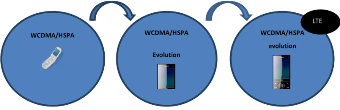
International Telecommunication Union (ITU). 3GPP specifications are based on evolved GSM specifications. 3GPP standardization encompasses Radio, Core Network and Service architecture. 3GPP has several Technical Specification groups (TSGs) which deal with specific working areas [26]. In Q3 of 2004, TSG RAN2 organised a workshop on 3GPP long-term evolution, this was the starting point of the development of the LTE radio interface. After the initial phase where targets and objectives of LTE were set, the TSG SA launched a corresponding work on the SAE, since it was important that LTE radio interface have suitable evolved system architecture. As HSPA was an evolution of WCDMA, building upon the basic WCDMA structure and with strong requirements on backwards compatibility to leverage on already existing networks, 3GPP has specified LTE as the RAN of the future. LTE targets more complex spectrum situations and has fewer restrictions on backward compatibility. 3G evolution therefore consists of two parallel tracks each with its own merits. Figure 2.1below illustrates the evolution of LTE over the different 3GPP releases over the years [27].
Rel 99 Rel 4 Rel 5 Rel 6 Rel 7 Rel 8 Rel 9Rel 10
WCDMA HSDPA HSUPA LTE LTE
Advanced
HSPA HSPA+
Figure 2.1: Summary of RAN evolution
3GPP Release 99/Release 4 was the first release of the third generation specifications was essentially a consolidation of the underlying GSM specifications and the development of a new UTRAN radio access network. A foundation was laid for future high-speed traffic transfer in both circuit switched and packet switched modes. A comprehensive review of the Release 1999 features is held in the summary of all Release 99 features document, the latest version being TR 21.101. Release 99 features can be summarized as follows [18];
Multiple access method: CDMA
Duplexing method: FDD and TDD
Channel Bandwidth: 5 MHz/1.6 MHz
Chip rate: 3.84 Mcps/ 1.28 Mcps
Speech Coding: AMR
2
Technical Specification Group Radio Access Network (TSG RAN) is a group within 3GPP that is responsible for the definition of the functions, requirements and interfaces of the UTRA/E-UTRA network in its two modes, FDD & TDD. More precisely: radio performance, physical layer, layer 2 and layer 3 RR specification in
UTRAN/E- Modulation: QPSK
User bitrates: 384 kbps PS, 64 kbps CS
Services: mobile TV, video calling
3GPP Releases 5 and 6 define the basis for mobile broadband access. In release 5, the following features were introduced were HSDPA: 16QAM, 14.4 Mbps on the downlink 0.4Mbps on the uplink
3GPP Release 6: HSUPA with 5.76 Mbps on the uplink, 14Mbps on downlink
3GPP Release 7: HSPA+ Downlink MIMO, 64QAM, Uplink 16QAM, Peak data rates of 28 Mbps on Downlink, 11.5Mbps on Uplink
3GPP Release 8 : DC-HSDPA, 42.2 Mbps on the downlink and 11Mbps on the uplink
3GPP Release 9: HSDPA + MIMO on the uplink and 84 Mbps on the downlink bps and DC-HSUPA on the uplink
3GPP Release 10: 168 Mbps and 4-carrier HSDPA on the downlink
From the above release descriptions, it is apparent that a lot of work has been done from the advent of GSM to LTE. The first set of LTE release 8 specifications were finalized in the last quarter of 2007, but it was only until 2009 that the LTE commercial specifications were made. Work on LTE Advanced aims to happen with release 10 and finalization is expected in Q1 and Q2 of 2011.
2.5.3 Why move to LTE?
The LTE Radio Access Network (also called the Evolved UMTS Terrestrial Radio Access Network ,E-UTRAN), is expected to substantially improve end-user throughputs, network capacity and reduce user plane latency, bringing a significantly improved user experience with seamless mobility. With the emergence of Internet Protocol (IP) as the protocol of choice for carrying all types of traffic, LTE will provide support for IP-based traffic with end- to-end Quality of Service (QoS). Voice traffic will be supported mainly as Voice over IP (VoIP), enabling better integration with other multimedia services. Initial deployments of LTE are expected by 2011 with commercial availability on a larger scale expected 1-2 years later. A key motivation is that LTE delivers on two separate axes. Previously, new network technologies mainly focused on improved performance. LTE however, not only delivers substantial performance improvements, but also creates new business models for operators as
follows [18] [25]:
LTE enables new applications: With expected throughput in excess of 100Mbps and latency lower than 10ms, LTE will provide mobile subscribers with a user experience very comparable to what they have at home today, with xDSL and cable connections. In addition,
LTE breaks the boundaries between “home and outside”, meaning that applications can be shared between the home computer and outside the home. In addition because of LTE’s lower cost per bit, it also makes a number of typically gigabyte hungry applications, cost effective and viable to use in a mobile environment [28].
LTE has a future-proof data rate: Do people really need the kind of bandwidth LTE provides? Studies show different usage case scenarios in 2-3 years’ time (mobile, laptop-nomadic in hotspot and household via xDSL) that the maximum bandwidth needs can be achieved with LTE whereas 2G and 3G wireless technologies would struggle to deliver enough capacity. 2G and 3G technologies are more uplink limited.
Seamless mobility: LTE is a key technology in realizing the full promise of seamless mobility. The LTE, IP Based Evolved Packet Core, allows for connectivity and hand-over to other access technologies, including all 3GPP & 3GPP2 technologies, such as GSM, UMTS, CDMA/EV-DO, as well as Wi-Fi or even fixed line broadband services like Digital Subscriber Line (DSL) , Gigabit Passive Optical Network (GPON). And, the IMS layer or service layer will provide the user seamless continuity of services.
Better business model: With greater spectrum efficiency, simpler architecture and the ability to re-use low frequency spectrum, LTE will boast of much improved capacity for both voice and data delivered at a significantly lower cost compared to legacy technologies. These improvements contribute to a lower cost per bit for both voice and data services. In fact, some simulations show that voice services on UMTS are several times more expensive than LTE. The relative total cost of ownership (TCO) for LTE by subscriber’s GB/month also presents significant improvement opportunities over existing 3G networks [7][29].
2.6 Conclusion
A basic introduction to cellular network evolution over the past two decades has been given in this chapter. The chapter briefly talks about characteristics of different generations of cellular networks from earlier days and how they have changed along the years. Characteristics include the frequency band used, modulation and coding schemes and network elements, to mention but a few. It shows that as society changes, there is need for more sophisticated telecommunications services, which fosters network evolution. As demand grows, it ceases to be simply about providing the service but how efficient and effective the service is and how an operator can keep a competitive edge while providing the service. The need for seamless handover across networks is therefore one of the demands that come along with evolution.
3
LTE and UMTS Networks
3.1 Introduction
This chapter gives an overview of UMTS and LTE/EPC architecture, the logical network elements and interfaces, radio procedures and handovers. UMTS and LTE utilize network architecture similar to second generation networks. As in previous generations, the network is grouped into the Radio Access Network (RAN) and the Core Network (CN). UMTS radio network introduces several new protocols and designs based on the Wideband Code Division Multiple Access (WCDMA) radio access technique while the LTE network is based on the Orthogonal Frequency Division Multiple Access (OFDMA) technique. In this chapter, UMTS is first discussed then it is followed by a discussion on LTE.
3.2 Universal Mobile Telecommunications System (UMTS)
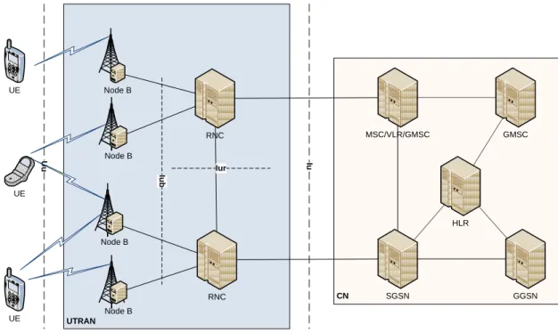
The UMTS architecture is shown in Figure 3.1. It shows the UE, the base station (known as the Node B), the Radio Network Controller (RNC) which together make up the UTRAN. Also shown are the Core Network and the associated interfaces. UMTS entities shown in this figure are briefly described as follows [30]; UTRAN CN U u Iur Iu UE UE UE Node B Node B Node B Node B RNC RNC MSC/VLR/GMSC SGSN GGSN HLR GMSC Iu b
The UE: Consists of the Mobile Equipment (ME) and Universal Subscriber Identity Module (USIM).The ME is a radio terminal used for radio communication over the Uu interface. The Uu interface allows for communication between the UE and the UTRAN. The USIM is a smartcard that holds subscriber identity and performs authentication algorithms.
Node B: Is the UMTS base station and converts the data flow between the Iub and Uu interfaces. The Iub interface is used to carry messages between the NodeB and the RNC. The Node B also performs radio resource management functions.
The Radio Network Controller (RNC): controls radio resources (Node Bs).
Home Location Register (HLR): is a database in the CN that stores the master copy of the user’s service profile.
Mobile Services Switching Centre/Visitor Location Register (MSC/VLR) is the switch and database that serve the UE in its current location for Circuit-Switched services. The MSC switches the CS services while the VLR holds a copy of the visitor’s user profile.
Gateway MSC (GMSC) is the switch through which the UMTS connects to other CS networks.
Serving GPRS Support Node (SGSN) is similar to MSC/VLR except it is used for packet switched services.
Gateway GPRS Support Node (GGSN) is similar to the GMSC but in relation to packet switched services.
3.2.1 WCDMA Air Interface
This section presents the basic principles of WCDMA air interface, particularly those features that differentiate WCDMA from GSM and LTE. Main parameters are briefly introduced in section 3.2.2 while handovers in WCDMA are discussed in section 3.2.7.
3.2.2 Main Parameters in WCDMA
In this section some system design parameters of WCDMA are presented and briefly explained. They are summarized in the Table 3.1.
WCDMA is a wideband Direct-Sequence Code Division Multiple Access (DS-CDMA) system. That is to say user information bits are spread over a wide bandwidth by multiplying the user data with quasi random bits/chips derived from CDMA spreading codes. To support very high bit rates, the use of a variable spreading factor and multi-code connections is supported [7].
Property Description
Multiple access method DS-CDMA
Duplexing method Frequency division duplex/time division duplex Base station synchronization Asynchronous operation
Chip rate 3.84 Mcps
Frame length 10ms
Service multiplexing Multiple services with different quality of service requirements multiplexed on one connection Multi-rate concept Variable spreading factor and multi-code
Detection Coherent using pilot symbols or common pilot Multiuser detection, smart antennas Supported by the standard, optional in the implementation
Table 3.1: Main WCDMA Parameters [7]
The chip rate of 3.84Mcps leads to a carrier bandwidth of approximately 5MHz. DS-CDMA systems with a bandwidth of 1MHz e.g. IS-95 are referred to as narrowband CDMA systems. WCDMA supports higher user data rates and has certain performance benefits such as increased multipath diversity. WCDMA supports highly variable user data rates, i.e. Bandwidth on Demand (BoD) is well supported. The user data rate is kept constant during each 10ms frame. However, the data capacity among users can change from frame to frame. WCDMA supports both TDD and FDD modes [7]. WCDMA air interface allows for advanced CDMA receiver concepts such as multiuser detection and smart adaptive antennas. These can be used by the network operator to increase capacity and/or coverage. WCDMA is designed to be deployed in conjunction with GSM and higher generation cellular networks; therefore handovers between GSM and WCDMA are supported in order to be able to leverage the GSM coverage for the introduction of [7].
3.2.3 Generic Principles of CDMA Operation
Figure 3.2 illustrates the basic operations of spreading and dispreading for a DS-CDMA system. User data is assumed to be a BPSK-modulated bit sequence of rate R, the user data bits assuming the values of + OR - 1. The spreading operation multiplies each user data bit with a sequence of 8 code bits/chips. This is also assumed for the BPSK spreading modulation. Thus the resulting spread data is at a rate 8Xr and has a random appearance as the spreading code. The resulting code is then sent over the channel to the receiver. At the receiver, the spread sequence is multiplied by the 8 code chips used during the spreading of these bits. The original sequence is then recovered [18].
-1 1 -1 1 -1 1 -1 1 -1 1 Spreading code Data Spreading code Spreading code x Data Data =Spread signal x Data chip
Figure 3.2: Spreading and De-spreading principal of DS-CDMA
Increasing the signalling rate by a factor of 8 results in the widening of the occupied spectrum by the same factor, hence the term; “Spread Spectrum”. Dispreading restores the bandwidth proportional to R for the signal. Due to spreading and dispreading, the carrier to interference(C/I) ratio can be lower in CDMA than GSM. Since the wideband signal can be below the thermal noise level, its detection is difficult without knowledge of the spreading sequence. Thus, spread spectrum systems originated in military applications where secrecy is paramount. Spreading/dispreading in itself does not provide any signal enhancement for wireless systems. The benefits of WCDMA are rather realized indirectly [18];
The processing gain together with the wideband nature allows a frequency reuse of 1 between different cells of wireless systems. This feature allows increased spectral efficiency.
Several users sharing the same wideband carrier provides interferer diversity. That is to say the multiple access interference from many system users is averaged out. This boosts capacity and reduces the need to plan for worst case interference.
The above two benefits require the use of tight power control and soft handover to avoid one user’s signal blocking the others. This is further described in Sections 3.2.7 and 3.2.8.
With a wideband signal, the different propagation paths of a wireless radio signal can be resolved at higher accuracy than with signals at a lower bandwidth. This results in higher diversity content against fading and thus improved radio performance.
3.2.4 General Protocol Model for UTRAN
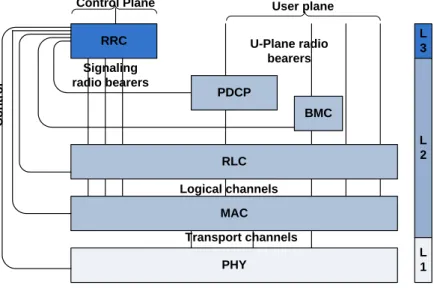
The general radio interface protocol architecture is shown in Figure 3.3. The physical layer provides service to the MAC layer which in turn offers services to the RLC layer via logic channels. In this thesis, the chief interest lies in the Radio Link Control (RLC) protocol layer as the RLC protocol provides retransmission services for both user and control data and thus can be used to determine delay/latency over the radio link. On top of the RLC there is the Radio Resource Control (RRC). It is responsible for maintaining a reliable connection between the UE and the UTRAN and especially manages radio resources. It is also involved in managing handovers [7].
The Packet Data Control Protocol exists in the user plane and is used for services in the PS domain. It contains compression techniques required for better spectral efficiency in IP packets transmitted over the radio. The Broadcast Multicast Control (BMC) protocol is a user plane protocol designed to adapt broadcast and multicast services on the radio interface.
PHY MAC RLC RRC PDCP BMC L 3 L 2 L 1 C o n tr o l
Control Plane User plane
Signaling radio bearers U-Plane radio bearers Logical channels Transport channels
Figure 3.3: UTRA Radio Interface Protocol 3.2.5 Radio Link Control Protocol (RLC)
In a system such as UMTS, the RLC protocol is used to transfer data reliably across the network. Each RLC instance is configured by the RRC to operate in either transparent mode (Tr), unacknowledged mode (UM) or acknowledged Mode (AM). Tr and UM RLC are unidirectional while AM is bidirectional [31][32].
In this thesis, RLC-AM is the choice as it is more reliable. RLC layer lies at layer 2 of the UTRAN protocol architecture. The RLC - AM layer is important in UTRAN and performs the following functions [7];
Transfer of user data: The protocol supports reliable data transfer. It can discard data that have not been successfully transmitted in a period of time or number of retransmissions. This is because it expects upper layer protocols to perform their own, end-to-end retransmissions as well.
Error correction: The protocol detects erroneous frames and either asks for a retransmission or discards them altogether.
Sequence number check, duplicate detection and in-sequence delivery of upper layer frames: The protocol detects duplicate frames by using sequence numbers and a frame window. It also delivers the frames in sequence. Out-of-sequence delivery is also supported.
Protocol error detection and recovery: The protocol detects a number of abnormal conditions and can request retransmissions or even reset itself if all other measures fail.
Flow control: The receiver can optionally change the sender’s window size to control the flow
Segmentation and reassembly, concatenation and padding: The super frames received from upper layers are segmented into smaller parts (if they are larger than the available space in a frame) and are concatenated to form frames of fixed size. Padding is added at the end of the frame if they are smaller than the indented size.
Ciphering: The protocol encrypts and decrypts the data exchanged. 3.2.6 Radio Resource Control and Mobility Management
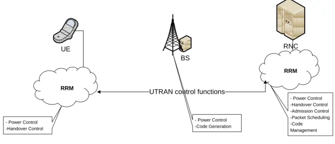
In WCDMA, RRC is a management responsibility done by UTRAN. RRC is located in the UE and RNC. RRC contains several algorithms aimed at keeping a high QoS. Figure shows the locations of the different RRC algorithms within the UTRAN [25].
RRM algorithms deliver information over the radio path, called the UTRA service. The protocol used for this service is the RRC protocol. The RRM contains several algorithms which include [25];
Code management: Deals with the management of codes generated by the base station and assigned to users. Each user in a WCDMA network is assigned a unique code that it uses to access radio channels.
Handover control: controls handover algorithms and procedures
Power control: Used for Optimisation of power levels between the BS and UE in order to avoid interference among users.
UTRAN control functions BS UE RNC - Power Control -Handover Control - Power Control -Code Generation - Power Control -Handover Control -Admission Control -Packet Scheduling -Code Management RRM RRM
Figure 3.4: Radio Resource Management and Radio Resource Control functions In this research report the RRM algorithms of major concern are Handover and Power Control. UTRAN level Mobility Management refers to those functions which RNC handles in order to keep the UE in touch with the UTRAN radio cells, taking into account the user’s mobility within the UTRAN and the type of traffic or Radio Access Bearer(s) it is using. The concept of UTRAN mobility is based on a cell, UTRAN Registration Area (URA), Radio Network Temporary Identifier (RNTI) and the Radio Resource Control state transition model [25].
3.2.7 Handover Control in WCDMA
Handover is one of the most important ways to guarantee user mobility in a mobile communications network. Handover is the process of maintaining an active connection with a moving subscriber. The basic concept is when a subscriber moves from one cell to another, connectivity to the old cell is released while a new connection is made with the target cell. Handover control is a complicated issue in cellular systems and especially in CDMA systems [33].
There are several reasons why handover is activated. First is that the air interface connection does not fulfil the desired criteria set for it anymore and thus the UE or the UTRAN initiates actions to improve the connection. In WCDMA, real-time handover is used in circuit switched calls. In the case of packet switched calls, handovers are mainly achieved when neither the network nor the UE has any packet transfer activity. Regardless of the type of handover, criteria that are used to decide the need for handover are performed. Execution of the handover depends on the strategy implemented in the system. However, most criteria for handover are signal quality, user mobility, traffic distribution and bandwidth utilisation [33].
Signal Quality handover occurs when the quality of the signal strength falls below certain parameters specified in the RNC. Signal deterioration is detected by the periodic signal measurements carried out by the UE and the Node B. Handover due to poor signal quality may be done on either the uplink or the downlink.
Handover due to Traffic occurs when the traffic capacity of a cell has reached its maximum or approaches it. In this case, if a UE is close to the edge of a cell with high load, it may be handed over to neighbouring cells with less traffic load. This allows the system load to be distributed more uniformly.
The number of handovers is dependent on how mobile a subscriber is. If the UE is moving fast in the same direction, it can be assumed that it will have more handovers to the UTRAN. To avoid unwanted handovers, a UE with high speed may be handed over from microcells to macrocells. Slow moving UEs can be handed over to microcells. The decision to perform a handover is always made by the RNC currently serving the UE, except in the case of handover due to traffic reasons. In the latter case, the MSC may also make the decision. Other reasons such as change in service may also lead to a handover [33].
3.2.7.1 Handover Process
The figure below illustrates the basic handover process consisting of three main phases namely measurement, decision and execution. The handover procedure discussed here is specifically for WCDMA although some principles apply to other cellular systems [18][25].
MEASUREMENT DECISION EXECUTION - Measurement criteria - Measurement reports - Algorithm parameters - Handover criteria - Handover signalling - Radio resource allocation
Figure 3.5: Basic Handover process
Handover measurement provisioning is an important task for good system performance for two reasons [33].
Excess measurement reports by the UE or handover execution by the network increases network signalling which is undesired.
The UE constantly measures signal strength of neighbouring cells and reports to the RNC. 3GPP TS 25.331 specifies the reported measurements and groups them in different categories. The different measurements are [34]:
Intra-frequency measurements which look at strength of the downlink physical channels for signals with same frequencies.
Inter-frequency measurements which look at the strength of the downlink physical channels for signals with different frequencies.
Inter-system measurements which measures the strength of the downlink physical channels belonging to another radio access system other than UTRAN e.g. GSM.
Traffic volume measurements contain measurements for uplink traffic volume.
Quality measurements include quality parameters e.g. downlink transport block error rate.
Internal measurements of UE transmitted power and received signal level. The measurement events, on the other hand may be triggered based on [34];
Change of best cell
Change in the Primary Common Pilot Channel (CPICH) signal level
Change in the P-CCPCH signal level
Changes in the Signal-to-Interference (SIR) level
Changes in the Interference Signal Code Power (ISCP) level
Periodical reporting
Time-to-trigger
WCDMA specifications provide various measurement criteria to support handover mechanisms in the system. It is important to choose the best measurement procedure for good system performance. Handover signalling load can be optimised by fine-tuning trade-off between handover criteria, handover measurements and the traffic model used in network planning [34].
The decision phase consists of assessing the overall QoS of the connection and comparing it with the requested QoS attributes and estimates from neighbouring cells. Depending on the outcome of the comparison, the handover procedure may or may not be triggered. The SRNC checks whether the values indicated in the measurement reports trigger criteria were set. If they trigger, then it allows