A Hybrid Cache for a Popularity-based Cache Management Scheme for a RAID Storage System
A Thesis
SUBMITTED TO THE FACULTY OF UNIVERSITY OF MINNESOTA
BY
Yiming Tao
IN PARTIAL FULFILLMENT OF THE REQUIREMENTS FOR THE DEGREE OF
MASTER OF SCIENCE
Adviser:David J. Lilja
Acknowledgements Thanks to My Adviser David J. Lilja And My colleague Bingzhe Li
Dedication
This thesis is dedicated to My parents
Yaping Zhang and Quan Tao
Chapter 0
Abstract
In this paper, we propose a method of using hybrid cache to improve the cache hit rate of popularity-based caching management scheme for Redundant Array of Inexpensive Disks(RAID) architecture. The hybrid cache we proposed consists of Solid State Drive(SSD) and battery-backed Dynamic Random Access Memory(DRAM). The main purpose of using SSDs as cache for RAID is for energy saving in this thesis, however, SSDs have few special features: 1. SSDs do not support in-place updates, thus a erase operation has to be performed before a page gets updated. 2. SSDs have relatively low endurance, so frequent erasures and write operations can wear out SSD units and reduce the life expectation of SSDs. Dongkyu Lee et al [1] proposed a popularity-based management scheme(PBM) to reduce write operations on SSDs cache, this scheme works well under web-sever-based environment where a small number of hot files are accessed frequently. However, because PBM calculates the popularity of files and caches popular files into SSD cache only at the end of each time period, it is not able to exploit the temporal locality hidden in the I/O requests, which leads to a reduced cache hit rate. In this paper, we propose a method of using a SSD-Battery Backed DRAM hybrid
cache to reach both a high cache hit rate and low write size count on SSD. DRAMs have very good endurance compared to SSD, and DRAMs also support in-place update. So we can take advantage of high endurance and in-place update of DRAMs to explore the temporal locality of user requests. Our SSD-DRAM Hybrid Management Scheme(SDHM) will implement PBM in SSD and simple replacement caching algorithm like Least Recently Used(LRU), Least Frequently Used(LRU) and Random Replacement in DRAM. While popular files in SSD can service the frequent read requests on popular files, DRAM with simple replacement algorithm can help to exploit the temporal locality. Also, Considering the volatility of DRAM, we use battery-backed DRAM in our SDHM in case of sudden power breakdown. We simulated both SDHM and PBM along with few other caching schemes using real traces, the results show that, compared to PBM, our SDHM maintains both a high cache hit rate and a low SSD write count.
Table of Chapters
0. Abstruct...iii
1. List of Tables...vi
2. List of Figures...vii
3. List of Pseudo Codes...viii
4. Abstruct...iii
5. Introduction...1
6. Background...4
7. Related Work...16
8. Hybrid Cache on Energy Efficient RAID...21
9. Simulation...28
10. Simulation Result...32
11. Conclusion...45
List of Tables
Table1. DRAM, Flash, HDD Comparison ...16
Table 2. Traces Basic Statistics ...30
List of Figures
Figure 1, RAID Basic Terms...6
Figure 2 RAID Level 0, 1, 5, 6, 10...9
Figure 3 RAID Operating Modes...11
Figure 4 Hybrid Cache Management Scheme Architecture...25
Figure 5 Percentage of Total Requests Related to Top 3% Most Popular Files...30
Figure 6 Matching Ratio for most Popular 3% Files...31
Figure 7 Read Cache Hit Rate Comparison... 35
Figure 8 SSD Write Size Count Per 64K Pages Comparison...37
Figure 9 SSD Write Size Count Per 64K Pages Comparison II...40
List of Pseudo Codes
1. Simple SSD Caching Scheme Pseudo Code...18
2. Popularity-Based Cache Management...20
Chapter 1
Introduction
RAID(Redundant Array of Inexpensive Disks) is a widely used storage system in data centers due to its relatively high performance, fault-tolerance and low cost. In a large data center, huge number of RAID systems built by hard disk drives(HDDs) consume a lot of power and lead to a extremely high cost. The federal Environmental Protection Agency (EPA) reported
electricity consumption of U.S. data centers in 2006 was about $4.5 billion [6].
A lot of works have been done on how to build energy-efficient RAID system. One idea is using Solid State Drives(SSDs) as a big cache to buffer read and write requests, this can reduce I\O stress on hard disk drives and leave hard disk drives in standby mode as long as possible[2]. Lee and Koh [1] proposed a popularity-based SSD cache management(PBM) scheme for RAID. PBM updates SSD cache with the most popular data periodically, it computes popularity of data based on its frequency of being accessed during
previous time period. Eg. If a file had been accessed more often than another file during previous period of time, then the file is considered more popular. Also, large files with relatively low popularity are excluded because with limited cache size, caching large files can reduce the cache hit rate. Under web-server based environment, Lee’s method shows good results on
reducing write size count on SSD. This result is based on two observations under web-server-based environment: 1. A small percentage of files are accessed more frequently than the rest, as a small percentage of popular files are cached in SSD, I\O stress on RAID can be reduced significantly; 2. Current hot files have a large chance to maintain their popularity in the near future, so popular files in the near future can be predicted based on previous popular files. Unfortunately, Lee’s result shows that the PBM can cause a low cache hit rate. There are at least two reasons why the cache hit rate drops when using Lee’s scheme:
1. Since data in the SSD cache will not be updated until the end of current period, the popularity-based caching scheme is unable to exploit the
temporal locality hidden in I\O requests.
2. Even though hot files are highly likely to keep their hotness in the near future, there are fairly amount of previous popular files will lose their
popularity and some previous cold files may get accessed more often in the next time period.
Using the popularity caching scheme, I\O requests to new hot files can be missed in the cache. Since a higher cache miss rate leads to more I\O stress on RAID, the popularity-based caching scheme leads to less standby mode time and more power consumption for RAID potentially.
Hybrid cache structure has been studied widely for its performance, power consumption and endurance. However people didn’t explore much on the possibility of using SSD-DRAM hybrid cache for energy efficient RAID, especially under web-server-based environment.
To solve the above problem, in this paper, we propose an idea using a SSD-DRAM hybrid cache architecture and a hybrid cache management scheme. There are two parts in the hybrid cache, SSD and battery-backed DRAM. PBM is implemented on SSD, and we take advantage of the fact that DRAM has a better endurance than SSD, so temporal locality can be
exploited by implementing normal replacement caching scheme like LRU in DRAM. Since DRAM is a volatile memory, it loses all data when power supply is lost, to prevent accidentally data loss, we use battery-backed DRAM in our hybrid cache architecture. For those previously cold files
which just turn into hot files in current period, they have large chance to stay in DRAM as long as their access frequency/size ratio is relatively high. We simulated PBM and SDHM with real web-server traces, simulation results show that SDHM provides a higher cache hit rate than popularity-based caching scheme under different cache sizes and SSD-DRAM partition ratios. Since most updates happens in DRAM, a low number of SSD write size count is maintained.
Chapter 2
Background:
2.1. Hard Disk DriveA Hard Disk Drive(HDD) consists of platters, spindle read\write heads actuator and mechanical arms. Multiple platters are mounted on a single spindle, platters are covered with magnetic materials on both sides, surfaces of platter are divided into “tiny spaces” which maintain polarity information, this is how HDDs represent bit “0” and “1”. Polarity for those “tiny spaces” can be changed when a write operation happens. While the disk is operating, the platters rotate at a fixed speed, which is normally measured as
revolutions per minute(RPM). For each platter, there is a pair of read/write heads mounted on each mechanical arm, those mechanical arms however, are mounted to a shared actuator. To control the actuator precisely, a small electrical current is applied on motor attached to the actuator, so the actuator can move in both directions. The movement of actuator and spinning of platter enable read/write heads to access any region on each platter.
2.2. RAID Overall View
Storage I/O performance has lagged far away behind computation power we have today. Computation power has been keeping increasing continuously, doubled almost every two years, the lagged storage I\O performance leaves a deep gap between storage and computation. Due to the mechanic nature of HDD, its performance is largely limited by the mechanical limits like
actuator rotation, read and write arm movement. So it is important to explore the parallelism between disks arrays to improve the I\O subsystem
performance.
RAID (Redundant Array of Independent Disks) has been used widely due to its fast I/O performance and high reliability. Its performance, reliability, failure recovery and power consumption has been well studied.
2.2.1. RAID Level
RAID is a cost-effective, reliable, relatively high performance storage solution. It offers higher I\O performance by reading/writing in parallel on disks array. It stores redundant data to improve reliability. There are
different levels for RAID, each level provides certain level of parallelism and redundancy. The most popular RAID levels are RAID0, RAID1, RAID5, RAID6, RAID10.
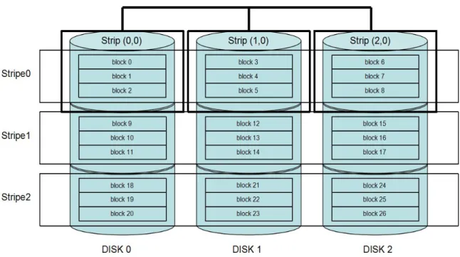
Before we talk further about RAID levels, there are some general definitions for RAID need to be made clear. As you can see in Figure 1, there are 5 disks in the array, each single disk is divided into many data chunks, called strip, a strip contains a set of data blocks. A stripe including all strips across all disks. Some strips are used to store user data, called data strips, some strips are used to store redundant data to provide redundancy, called parity strips.
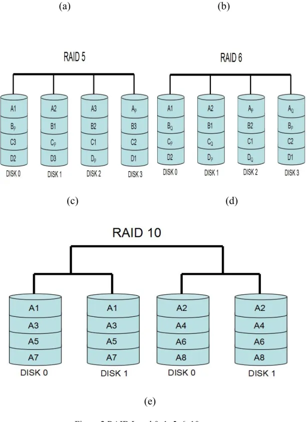
RAID0[Figure2. a] simply distributes fixed-size data strips evenly into two or more different disks. RAID0 provides no redundancy but it gives performance benefit for writing operation since there is no need to update parity strips.
RAID1[Figure2. b] is simply a mirroring of data disk, so there are in total two disks with exactly the same data. It provides redundancy
however not in a efficient way. This is useful when read performance or reliability is more important than data storage capacity.
RAID5[Figure2. c] uses block-level striping with one parity strip, so it could handle one disk failure. RAID5 differs from RAID4 in a way that parity strips are distributed into different disks rather than in a single disk. By doing so, it removes the I\O bottleneck of parity disk. At least three disks are needed to configure RAID5.
RAID6[Figure2. d] has an extra parity block than RAID5, thus, two disk failures could be tolerated. Same as RAID5, RAID6 uses block-level striping, and parity blocks are distributed across all member disks
RAID10[figure2. e] is a mix of RAID 0 and RAID 1. RAID 10 is a stripe of mirrors.
(a) (b)
(c) (d)
(e)
2.2.2. RAID Operating Modes
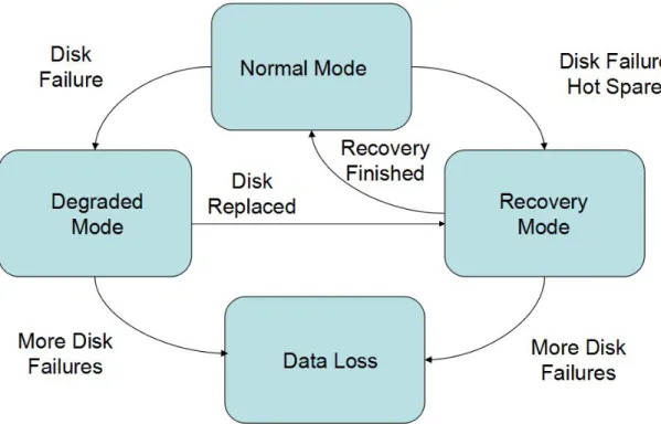
Normal Mode: When all disks in the RAID system are operating normally and no failure happens, the RAID system is operating in normal mode. In normal mode, RAID can service user requests with all its resources so the performance is optimal.
Degraded Mode: When one or more disk fails and the number of failed disks can be tolerated by current RAID level, user requests can still be serviced, this is called degraded mode. With redundancy data, RAID is able to service user requests by recovering lost data from survival member disks on the fly. Since the RAID system has to recovery data when user request need to access the missing data, it has worse overall performance compared to the performance in normal mode.
Recovery Mode: When disk failure(s) happen(s) in RAID system, redundant data are used to recovery the missing data spare disks, then RAID is under recovery mode. There are two types of recovery modes. One is online recovery mode, where RAID system gives priority to servicing user requests than recovering missing data, another is called
offline recovery, where RAID system devotes all its resources to recover missing data.
Data Loss: When the number of failure disks exceeds the limit RAID could handle, it leads to permanent data loss. So RAID is vulnerable when in degraded or recovery mode, any additional disk failures can lead to user data loss.
How RAID switches between different operating modes is illustrated in Figure 3.
2.3. Solid State Drive(SSD)
Flash memory is a novel storage media which is widely used in portable devices like MP3 and mobile phones. Flash memory has many good features like low-power consumption, non-volatility, high I\O throughput and high mobility.As the price of flash-based SSD continuously goes down during the past years, it is used more frequently on storage systems for personal
computers and enterprise servers. It is a clear trend that the flash-based SSDs are replacing HDDs. SSDs are preferred especially for its low power consumption compared to HDDs.
SSDs have many interesting features which differ itself from traditional HDDs. First, a block has to be erased before write. This is because write operation could change bits in a block from logical value ‘1’ to logical value ‘0’, but not from logical value ‘0’ to logical value ‘1’. So before a write operation be executed on a block, that block has to be erased first. Secondly, erase operations are executed in unit of blocks while write operations are execute in unit of pages. In flash memory, a block contains a set of
sequential pages. Because of above two features, special software is needed for mapping the logical page address from host system to physical page
address. Flash translation layer (FTL) is used for this purpose. The address mapping schemes of the FTL can be categorized into page-level, block-level, and hybrid mapping depending on the mapping granularity. By doing this, a logical page can be mapped to any physical page in flash memory device.
2.3.1.SSD Architecture
To enhance the I\O performance of the SSD, interleaving between many flash memory chips becomes a common technique. Different channels can be used during the same period of time. Flash chips using different channels can be programmed independently, thus the page programming times for different flash chips can be overlapped. The interleaving technique can also be applied between flash controller and flash chips, one flash memory
controller can access more than one flash chips in the same period of time by interleaving, thus we can write to multiple interleaved chips during the same period of time. However, the data bus becomes the bottleneck at this point since multiple flash chips can not transfer or receive data in the same time through a single bus, they have to share one bus and use it in turn, so the data transfer time cannot be overlapped. To utilize such a parallel
architecture, sequential data are distributed across multiple flash chips to exploit parallelism .
Flash memory has few drawbacks need to take into consideration when use it in storage system. The main drawback is flash memory has a low
endurance, this means flash unit can wear out after certain number of erase/write operations. Due to this feature of flash memory, wear-leveling and garbage collection techniques are used in flash memory to guarantee better endurance and performance.
2.4. Dynamic Random Access Memory
Dynamic random access memory (DRAM) is mainly used in modern memory system as cache. A DRAM cell including a capacitor to store one bit of data as electrical charge. However, as charge stored in the capacitor leaks over time, DRAM need periodically refresh operation to restore electrical charge in DRAM cells to maintain data integrity. Every single DRAM cell has to be refreshed periodically every refresh interval, this is specified in DRAM standards [3].
A DRAM system can be divided into ranks. Each rank consists
Banks are independent between each other, so banks can be accessed in parallel, this provides bank level parallelism [4] and improve the DRAM performance significantly.
2.5. Comparison between DRAM, SSD and HDD
The comparisons between DRAM, SSD and HDD are listed in table below. HDDs are cheap, with almost infinite read/write cycles, but vulnerable to shocks, and relatively slow and energy-consuming.
SSDs are a lightweight, more shock resistant, storage media with better read/write performance when compared with HDD. However it does have some weaknesses like limited life cycle and relatively higher price per capacity.
DRAMs are even faster than SSD in terms of read and write, it has excellent endurance. However, the price per capacity for DRAM is really high
compared to SSD and HDD. DRAM is a volatile memory, all data stored in DRAM will be lost at power failure, so in this thesis, we use battery-backed DRAM.
Attributes DRAM NAND Flash HDD
Non-Volatile No Yes Yes
Operating Power
<363mW*[8] Up to 5.0 W[9] ~8W [10]
Idle Power[7] ~100mW/GB ~10mW/GB ~10W/TB Endurance Infinity [7] 104-105[7] Infinity
Bandwidth[7] ~ 5-40 MB/s per die ~200MB/s per drive Page read latency[7] 20-50ns ∼25 µs ∼ 5 ms Page write latency[7] 20-50ns ∼500 µs ∼ 5 ms
Table 1 DRAM, Flash , HDD Comparison [7] [8][9][10]
*. The operating power is estimated by operating voltage and operating current.
Chapter 3
Related workThere are a lot of work has been done on how to build energy-efficient storage systems. Some studies focuses on using multi-speed disks that have two or more rotational speed levels in active mode, related worked were presented by Gurumurthi et al. [11]. and Carrera et al. [12]. Some work focuses on keeping disks in standby mode as long as possible in traditional disk arrays [13]. Some studies consider generating redundant data by
copying original data to some free disk area to prevent unnecessary spin up [14]. Meanwhile people are also trying to improve the energy efficiency by using cache in hardware controllers. Some studies have focused on pre-fetching schemes [15], while some studies have proposed caching schemes [16] for energy efficient disk arrays.
3.1. Use SSD as Cache on RAID
Hyo J. Lee et al. proposed a method of using SSD as a big cache to buffer small footprint[2], thus keep HDDs stay in energy-saving mode as long as possible. Lee’s work is base on the observation that in a large data center, given a trace of a day, only small percentage of data are accessed compared to the total volume of data. Lee analyzed HP cello99 trace as an example in her work, the average size of footprint is less than 1.5% of total data size. In
Lee’s work, a very simple caching algorithm is used, First, when a read request arrives, a copy of the read request is copied to the SSD, so that future requests may be serviced by the SSD. Then, for writes, all writes are
buffered in SSD so that the interval between requests may be increased and thus reduce activities at RAID disks.
The caching scheme described in Lee’s paper can be described in pseudo code 1:
1. ifrequest type is read:
2. ifrequested data in SSD:
3. read requested data from SSD
4. read hit count increments
5. else ifrequested data not in SSD:
6. read requested data from RAID
7. write requested data to SSD
8. read miss count increments
9. else ifrequest type is write: 10. ifrequested data in SSD:
11. update requested data in SSD 12. write hit count increments 13. else:
14. write requested data to SSD
15. write miss count increments
From Lee’s work, a good improvement(more than 14%) on power
consumption has been seen. However, caching data in SSD lead to frequent write operations, which shorten the life expectation of SSD dramatically.
3.2. Popularity-Based Cache Management Scheme
Lee, DongKyu and Koh et al.[1] proposed an idea to dramatically reduce the frequency of write operations on SSD. This idea is based on two:
observations:
In a web-server-based environment, majority of requests are reads, and a small percentage of hot files are related to a majority of total read
requests.
Popular files have large chance to maintain popularity in the near future.
The basic idea is to analyze I\O activities from previous period, calculate file popularity based on access frequency of each file, then cache hot files in SSD. Files cached in SSD will stay in SSD until the end of current period. See pseudo code 2:
Repeat:
1.calculate popularity of each file 2.cache popular files to SSD 3.whilein current time period: 4. ifrequest type is read:
5. ifrequested data in SSD:
6. read requested data from SSD
7. read hit count increments
8. else ifrequested data not in SSD:
9. read requested data from RAID
10. read miss count increments
11. else ifrequest type is write:
12. ifrequested data in SSD:
13. update requested data in SSD
14. write hit count increments
15. else:
16. write miss count increments
Pseudo Code 2: Popularity-Based Cache Management
This scheme helps decreasing write size count dramatically when compared with normal updating based caching scheme(like least recently used(LRU), least frequently used (LFU)). However, since the hotness of a file can
change over time, some previous hot files may not be popular any more in the next period, and this idea gives up exploiting the temporal locality in the web-server-based environment.
Chapter 4
Hybrid Cache Architecture and Caching Scheme on RAID
In this Chapter we describe our SSD-DRAM hybrid cache and SSD-DRAM Hybrid Management scheme(SDHM) in detail.
There are two parts inside hybrid cache, SSD and battery-backed DRAM, considering the price per capacity of DRAM is much higher than that of SSD, the majority of hybrid cache is consist of SSDs and the rest are DRAMs. We use battery-backed DRAMs in our hybrid cache design because DRAMs has larger chance to lead to data loss when sudden power cutoff happens.
PBM is implemented in SSDs. The most popular files are cached in SSDs to service read requests. To decide the popularity of files, analysis on previous log has to be done at the end of each time period. Also, to prevent caching large size files into SSDs, the access frequency-file size ratio is calculated for each file. If the frequency-size ratio for a specific file is higher than average, then we say this file is with popularity above average[1].
4.2. DRAM With Updating-Based Caching Scheme:
To exploit the temporal locality and reduce the time of write operation on SSDs, we implement normal updating-based caching scheme in DRAMs(eg. LRU, LFU, random). To prevent sudden power cutoff, battery-backed
DRAMs are used in this architecture to improve the reliability of the system.
4.3.SSD-DRAM Hybrid Cache Management Scheme SDHM is described in figure 4.
(a)
(c)
Figure 4 Hybrid Cache Management Scheme Architecture
In figure 4 (a), at the end of each time period:
Calculate popularity of all files accessed in the last time period.
Cache popular files into SSDs. To prevent caching a popular file with large size into SSDs, frequency-size ratio is calculated for comparison, see [1].
In this case, we can see from figure 4(a) that data A1, B2, C1, D2have been
cached into SSDs.
In figure 4 (b), a read request on data C2is coming, SDHM first checks if
DRAMs have C2, if found, then services the request by data in DRAM, if not
found, then checks SSDs the same way as checking DRAM. In this case, the request missed both in DRAM and SSD, at this point, a read request on C2is
sent to RAID to service the request, then a copy will be buffered in DRAMs. In figure 4 (c), after data C2has been cached in DRAMs, before C2being
evicted from DRAMs, any following read request on C2will be serviced
In figure 4(d), a write request on C1is coming, the request is first missed in
DRAMs, then hit in SSDs. C1will be updated in SSDs and cause write
operation. Since under web-server-based environment, most of requests are reads, so this situation should not be common.
See pseudo code 3 for more information.
1. Repeat:
2. calculate popularity of each file 3. cache popular files to SSD 4. whilein current time period: 5. ifrequest type is read:
6. ifrequested data in DRAM:
7. read requested data from DRAM
8. read hit count increments
9. else ifrequested data in SSD:
10. read requested data from SSD
11. read hit count increments
12. else ifrequested data not in SSD::
13. read requested data from RAID
14. copy requested data to DRAM
15. read miss count increments
16. else ifrequest type is write:
18. update requested data in SSD
19. write hit count increments
20. else ifrequested data not in SSD::
21. copy requested data to DRAM
22. read miss count increments
Pseudo Code 3. SSD-DRAM Popularity-Based Caching Management
SSD-DRAM partition ratio is a important parameter for out hybrid cache caching scheme, if the ratio is too high, which mean SSDs take a dominant percentage in the hybrid cache, then our SDHM basically will behave like PBM. However, considering the cost per capacity for DRAM is much higher than that of SSD, the less DRAMs take in total hybrid cache, the cheaper the hybrid cache is. In this thesis, we consider hybrid cache with different
partition ratio and this will be seen in the simulation chapter.
In the SDHM, SSDs handle majority of read requests on popular files, we also take advantage of better endurance of DRAMs to exploit the temporal locality and to cache those files which just becomes hot files. That is the reason why SDHM can reach both a good cache hit rate and keep the write size count on SSD low.
Chapter 5
Simulation: 5.1.SimulatorTo simulate our hybrid caching scheme, we made a trace driven simulator call SDHM-sim[18]. SDHM-sim can simulate different caching scheme with different cache size and cache partition ratio. The current version of SDHM-sim can SDHM-simulate LRU, LFU, random, PBM and SDHM on the file level. The output of simulation is the write size count on SSD and cache hit rate.
5.2.Traces
In our simulation, We use Auspex traces originated from Berkeley[17], which is collected in 1993 during a week from a NFS web server from with 236 clients. The Auspex trace contains 7 files in total, each file records all I\O activities happens in one day of that week.
5.2.1. Trace Format
Each entry in these traces following the format of timestamp type action FID: fid OFF: offset SIZE: size HOST: host.
-type- can be one of Attr, Block, Dir, Delete, Open, Close. Attr indicates a getattr request.
Block or Dir indicates that a file block or directory was read or written over the network.
Delete indicates that the file was deleted.
Open and close indicates that a file was opened or closed. -action- is one of READ, WRITE
-fid- is a file identifier, which is a 16-digit hex number
-offset- is the offset within the file for a read or write for Open or Close, this shows the size of the file.
-host- client id that made the request 5.2.2.Trace Features:
These traces is widely used for research and have strong features as web-server-based traces:
a. There are more read requests than write requests, see table 2 :
Days Mon. Tues. Wednes. Thurs. Fri. Sat. Sun.
Total visited Files
Total Read/Writ e Size(bloc k) 751549231 675438999 1086473259 90078017 4 130211686 6 131611573 2 102454 3361 Total Request count(req uest) 2410920 2295546 2645254 2388914 2278337 2358047 229531 3 Write/Rea d Ratio 6.4% 5.1% 6.6% 5.9% 6.4% 6.0% 5.96%
Table 2 Traces Basic Statistics
b. Popular files take a good percentage of total accesses(See figure 5).
Figure 5 Percentage of Total Requests Related to Top 3% Most Popular Files
c.Today’s hot file has a large chance to be hot files tomorrow in the web-server-based environment. Figure 6 shows the match ratio for top 3% most
popular files between two consecutive days in a week. This basically means popular files are changing relatively slow, and there is a large chance that today’s popular file will still be popular tomorrow.
Figure 6 Matching Ratio for most Popular 3% Files
5.3.Parameters
To better understand SDHM, we run simulations with different total cache sizes,DRAM-total cache partition ratio and caching schemes. In the
simulation results part, you will see the result under different conditions as following:
Cache size: 64K pages, 256K pages, and 1024K pages DRAM-Total Cache Size Partition Ratio: 1:4, 1:16, 1:64
Caching scheme: LRU, LFU, Random, PBM, SDHM
5.4.Simulation details
a. For PBM, popularity of files are calculated based on log from previous day.
b. Files with size larger than cache size will not be cached. For example, in LRU caching scheme, assume the cache size is 64K pages, so a file with size 65K pages will not be cached, instead, the request will go directly to RAID. c. We assume all metadata are cached in higher level cache, so we filter the “Directory” or “Attribute” requests in traces.
Chapter 6
Simulation Result:
The simulated cache read hit rate and write size count on SSD per 64K pages with different parameters(cache size, cache partition ratio, caching scheme) are shown below.
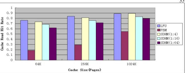
6.1.Cache Read Hit Rate
Figure 7 shows the cache hit rate for different cache sizes, hybrid cache partitions and caching schemes. Figure 7(a),(b),(c) focus on random, LRU, LFU replacement algorithm correspondingly.
We found few trends in figure 7.
1. PBM has a low hit rate when cache size is relatively small(64K), as the cache size increased, hit rate of PBM goes up. This is because for PBM, the larger the cache size is, the more files can be cached, and higher the chance that coming request find a hit in cache is.
2. The hit rate of SDHM is marginally lower than hit rate of normal replacement algorithms(random, LRU, LFU) when DRAM-to-total cache partition ratio is relatively high(1:4). As the ratio goes down, the hit rate of SDHM drops gradually. This is because SDHM only has part of the hybrid cache to exploit the temporal locality. The higher DRAM-to-total-cache ratio is, the better SDHM can exploit the temporal locality. 3. Both the hit rates of normal replacement algorithm and of SDHM are
higher than the hit rate of PBM under our simulation conditions. This is mainly because PBM cannot take advantage of temporal locality to increase hit rate, while normal replacement algorithm and SDHM does.
4. There are very limited difference between using random, LRU and LFU algorithm with SDHM.
(a) Random
(c)LFU
Figure 7 Read Cache Hit Rate Comparison
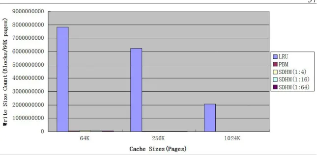
6.2. Write Size Count
Figure 7 shows the write size count on SSD per 64K pages for different cache sizes, different hybrid cache partitions and different caching schemes. Figure 8(a),(b),(c) focus on random, LRU, LFU replacement algorithm correspondingly.
We found few trends in figure 8.
1. Normal replacement algorithms(random, LRU, LFU) have very large write size count when compared to PBM and SDHM. The reason is for random, LRU, and LFU, the data cached is being updated dynamically to help increase the cache hit rate, and all these replacements are happening
on SSDs. While PBM only update cached data periodically and SDHM uses DRAM for frequent update to reduce write size count on SSD. 2. The write size count of LFU is significantly larger than that of random
and LRU. Since LFU evicts the least frequently used data, it is friendly to old hot data in the cache, but previously cold data have a large chance to be evicted, this can be a problem for data which just start gaining hotness.
3. As the cache size increasing, the write size count on SSD per capacity is decreasing. This is because cache size is getting larger, SSD can cache additional less popular files which have smaller chance to be visited in the future. Overall, the write size count per SSD capacity decreases.
(b)LRU
(c)LFU
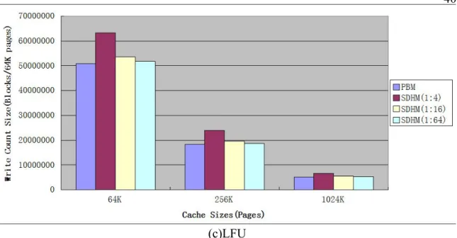
Figure 9 helps us to look closely on the write size count on SSD per 64K pages for PBM and SDHM. Figure 9 only shows write size count for PBM and SDHM for different cache sizes, partition . Figure 9(a),(b),(c) focus on random, LRU, LFU replacement algorithm correspondingly.
Few trends can be seen in figure 9.
1.For SDHM, as the DRAM-to-total-cache ratio going down, the write size count is dropping gradually. The reason for this is , with fixed cache size, as the DRAM-to-total-cache ratio going down, SSD size in hybrid cache gets increased, then SSD can cache additional less popular files which have
smaller chance to be visited in the future. Overall, the write update size/ SSD capacity is decreased.
2.The write size count of SDHM is marginally higher than write size count for PBM. The reason is the same as above.
3. For SDHM, what replacement algorithm is in use in DRAM doesn’t affect the write size count on SSD. This is because SDHM does frequent update only on DRAM.
(a)Random
(c)LFU
Figure 9 Write Size Count to SSD per 64K Pages Comparison II
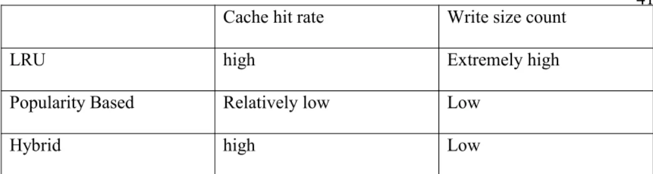
6.3.Comparison between different caching schemes
From figure 7, 8, 9, we can see when DRAM-total cache size ratio is high enough (like 1:4) and the cache size is large(like 1024K pages), SDHM can take advantage of both replacement caching algorithm( LRU,LFU and random) and PBM, reaches a high cache hit rate level(as high as LRU, LFU and random, much higher than PBM in our simulation conditions) and low write size count on SSD(marginal higher than write size count of PBM, much lower than LRU,LFU and random). The comparison is shown in table 3.
Cache hit rate Write size count
LRU high Extremely high
Popularity Based Relatively low Low
Hybrid high Low
Table 3 Different Caching scheme Comparison
6.4.Discussion: 6.4.1.read/write ratio
We use traces contain significantly more read requests than write requests, which makes it possible to use our hybrid caching to archive both high cache hit rate and low count of write size on SSD. However, for traces contain more write requests than read requests, then there will be a lot of write operations happens on SSD anyway, in that case, we don’t expect much improvement on write size on SSD for our hybrid caching scheme compared with popularity-based caching scheme.
6.4.2 Cache Size
From figure 7, we know that as the cache size is increasing, the cache hit rate get increased too. However, as the cache size is getting larger, more
write will hit in SSD, them update data in SSD, So a larger cache size can cause a increased write size count on SSD.
6.4.3.SSD-DRAM partition ratio
The SSD-DRAM partition ratio is quite important in our hybrid cache scheme. When there is a very strong temporal locality in coming requests, which means a requested data has a very large chance to be visited again very shortly, then the SSD-DRAM partition ratio can be relatively low. However, for workload with weak temporal locality, we may need higher SSD-DRAM partition ratio to better exploit temporal locality.
6.4.4. Time period
In our simulation, we choose time period be a day. The trade-off on picking time period is: if time period is too short, it is not enough samples there to determine which file is really popular in the previous time period, then the popularity calculation based on previous period may not be accurate enough to make prediction for the future. If the time period is too long, since popular data in SSD only updated at the end of each time period, what you cached in
SSD may not be popular any more as time elapses, in this case, a low cache hit rate can be expected.
6.4.5 Optimal Point:
Figure 10 shows how cache read hit rate and write size count under total cache size changes as cache partition ratio increases(total cache size 64K pages). We can tell from figure 10 that as the total cache size/ DRAM size goes up, both cache hit rate and write size count goes down. One can use previous requests to tune the system to reach the right cache hit rate and rate of wear-out on SSD. In this case we noticed that as the ratio goes beyond 32, the write size count doesn’t change much, so what one really need to think about is the cache hit rate when the ratio is great than 32. We also need to take the energy consumption of DRAM into consideration, since a large size of DRAM may consume too much energy.
(a)
(b)
Chapter 7
Conclusion:
In this paper, we explored the possibility of having a RAID use
SSD-Battery-backed-DRAM hybrid cache management scheme(SDHM) to reach both a high cache hit rate and low SSD write size count under web server based environment.
The simulation result shows that, having an overall consideration of cache hit rate and SSD life expectation, SDHM beats both normal replacement caching algorithm(LRU, LFU, random) and PBM. With proper cache size and DRAM-total cache ratio, SDHM provides both a high cache hit rate(as high as normal replacement caching algorithm like LRU, LFU, random provides, if not marginally lower) and a low write size count on SSD(much lower than LRU, LFU and random, marginal higher than PBM). The
contribution this paper makes is: proposed an improved popularity-based caching scheme on energy saving RAID with SSD-DRAM hybrid cache management scheme, by increasing the cache hit rate and maintaining a low
SSD write count, SDHM can archive more energy saving for RAID and longer life expectation of SSD cache under web-server based environment. Since in this thesis we only focus on cache hit rate and write size count, further work could be done on how the hybrid cache architecture improves the I\O request response time, and how to make the data in DRAM more secure under sudden power failure condition.
Reference:
[1] Lee, DongKyu. "Popularity Based Cache Management Scheme for RAID Which Uses an SSD as a Cache." IEEE Xplore. 2009 Fourth International Conference on Computer Sciences and Convergence Information Technology, 1 Jan. 2009. Web. 10 Nov. 2014. [2] Hyo J. Lee, Kyu H. Lee and Sam H. Noh, Augmenting RAID with an SSD for Energy Relief, The Workshop on Power Aware Computing and Systems (HotPower), http://www.usenix.org/events/hotpower08/, Dec. 2008.
[3] JEDEC,“Low Power Double Data Rate 3 (LPDDR3),”2012.
[4] Y. Kim et al.,“Thread cluster memory scheduling: Exploiting differences in memory access behavior,”in MICRO, 2010.
[5] C. Xue, Y. Zhang, Y. Chen, G. Sun, J. Yang, and H. Li,“Emerging non-volatile memories: Opportunities and challenges, in 2011 Proceedings of the 9th International Conference on Hardware/Software Codesign and System Synthesis (CODES+ISSS’11), Oct. 2011, pp. 325–334.
[6] Report to Congress on Server and Data Center Energy Efficiency Public Law 109-431. http://www.energystar.gov, 2007.
[7]Shimin Chen, Phillip B. Gibbons and Suman Nath. Rethinking Database Algorithms for Phase Change Memory.http://www.cidrdb.org/cidr2011/Papers/CIDR11_Paper3.pdf [8]512Mb: x4, x8, x16 SDRAM Micron,http://www.micron.com/~/media/Documents/ Products/Data%20Sheet/DRAM/512Mb_sdr.pdf
[9]Seagate Hard Drive Disks specification sheet, http://www.seagate.com/staticfiles/docs /pdf/datasheet/disc/desktop-hdd-data-sheet-ds1770-1-1212us.pdf
[10]Micron SSD Specification sheet. http://www.micron.com/-/media/documents/ products/data%20sheet/ssd/m500_2_5_ssd.pdf
[11]S. Gurumurthi, A. Sivasubramaniam, M. Kandemir, and H. Franke DRPM: dynamic speed control for power management in server class disks. In Proceedings of the 30th Annual International Symposium on Computer Architecture (ISCA’03), 2003. [12] E. V. Carrera, E. Pinheiro, and R. Bianchini. Conserving Disk Energy in Network Servers. In Proceedings of the 17th International Conference on Supercomputing, 2003. [13] C.Weddle,M. Oldham, J. Qian, A.-I. A.Wang, P. Reiher, and G. Kuenning. PARAID: a gear-shifting power-aware RAID. In Proceedings of the 5th USENIX Conference on File and Storage Technologies (FAST’07), 2007.
[14] H. Huang, W. Hung, and K. G. Shin. FS2: dynamic data replication in free disk space for improving disk performance and energy consumption. In Proceedings of the Twentieth ACM Symposium on Operating Systems Principles (SOSP’05), 2005. [15] S. H. Baek and K. H. Park. Prefetching with Adaptive Cache Culling for Striped Disk Arrays. In Proceedings of the Annual USENIX Technical Conference, 2008. [16] L. N. Bairavasundaram, M. Sivathanu, A. C. Dusseau, and R. H. Arpaci-Dusseau. X-RAY: A Non-Invasive Exclusive Caching Mechanism for RAIDs. In Proceedings of the 31st Annual International Symposium on Computer Architecture (ISCA’04), 2004.
[17]Auspex trace,tracehost.cs.berkeley.edu/auspex.html [18]https://github.com/taoyiming1/SDHM
![Table 1 DRAM, Flash , HDD Comparison [7] [8][9][10]](https://thumb-us.123doks.com/thumbv2/123dok_us/519375.2561201/25.918.160.812.120.720/table-dram-flash-hdd-comparison.webp)