Technische Berichte Nr. 99
des Hasso-Plattner-Instituts für
Softwaresystemtechnik
an der Universität Potsdam
Efficient and
Scalable Graph View
Maintenance for
Deductive Graph
Databases based
on Generalized
Discrimination Networks
Technische Berichte des Hasso-Plattner-Instituts für
Softwaresystemtechnik an der Universität Potsdam
Technische Berichte des Hasso-Plattner-Instituts für
Softwaresystemtechnik an der Universität Potsdam | 99
Thomas Beyhl | Holger Giese
Efficient and Scalable Graph View Maintenance for
Deductive Graph Databases based on
Generalized Discrimination Networks
Die Deutsche Nationalbibliothek verzeichnet diese Publikation in der Deutschen Nationalbibliografie; detaillierte bibliografische Daten sind im Internet über http://dnb.dnb.de/ abrufbar.
Universitätsverlag Potsdam 2015 http://verlag.ub.uni-potsdam.de/ Am Neuen Palais 10, 14469 Potsdam Tel.: +49 (0)331 977 2533 / Fax: 2292 E-Mail: [email protected]
Die Schriftenreihe Technische Berichte des Hasso-Plattner-Instituts für Softwaresystemtechnik an der Universität Potsdam wird herausgegeben von den Professoren des Hasso-Plattner-Instituts für Softwaresystemtechnik an der Universität Potsdam.
ISSN (print) 1613-5652 ISSN (online) 2191-1665
Das Manuskript ist urheberrechtlich geschützt. Druck: docupoint GmbH Magdeburg
Graph databases provide a natural way of storing and querying graph data. In contrast to relational databases, queries over graph databases enable to refer directly to the graph structure of such graph data. For example, graph pattern matching can be employed to formulate queries over graph data.
However, as for relational databases running complex queries can be very time-consuming and ruin the interactivity with the database. One possible approach to deal with this performance issue is to employ database views that consist of pre-computed answers to common and often stated queries. But to ensure that database views yield consistent query results in comparison with the data from which they are derived, these database views must be updated before queries make use of these database views. Such a maintenance of database views must be performed efficiently, otherwise the effort to create and maintain views may not pay off in comparison to processing the queries directly on the data from which the database views are derived.
At the time of writing, graph databases do not support database views and are limited to graph indexes that index nodes and edges of the graph data for fast query evaluation, but do not enable to maintain pre-computed answers of complex queries over graph data. Moreover, the maintenance of database views in graph databases becomes even more challenging when negation and recursion have to be supported as in deductive relational databases.
In this technical report, we present an approach for the efficient and scalable incremental graph view maintenance for deductive graph databases. The main concept of our approach is a generalized discrimination network that enables to model nested graph conditions including negative application conditions and recursion, which specify the content of graph views derived from graph data stored by graph databases. The discrimination network enables to automatically derive generic maintenance rules using graph transformations for maintaining graph views in case the graph data from which the graph views are derived change. We evaluate our approach in terms of a case study using multiple data sets derived from open source projects.
Contents
1. Introduction 9
1.1. State of the Art . . . 10
1.2. Prerequisites . . . 11
1.3. Running Example . . . 14
1.4. Outline . . . 16
2. Needs and Requirements 17 2.1. Needs . . . 17
2.2. Requirements . . . 18
3. Overview 20 3.1. Graph Database . . . 21
3.2. View Definition . . . 22
3.3. View Maintenance Engine . . . 24
3.4. Query Engine . . . 26
4. View Definition Approach 27 4.1. View Reference Graph . . . 27
4.2. View Modules . . . 29
4.3. View Models . . . 30
4.4. View Query Language . . . 32
4.5. View Graphs . . . 34
4.6. Mapping Nested Conditions to View Models . . . 35
4.7. Discussion . . . 41
5. Efficient and Scalable View Graph Maintenance 43 5.1. Traversing View Models . . . 44
5.2. Naive Batch Maintenance . . . 45
5.3. Batch Maintenance with Preservation . . . 46
5.4. Incremental Black Box Maintenance . . . 50
5.5. Incremental White Box Maintenance . . . 55
6. Evaluation 58 6.1. Evaluation Setup . . . 58 6.2. Evaluation Results . . . 60 6.3. Evaluation Discussion . . . 67 6.4. Threats to Validity . . . 68 7. Related Work 69 7.1. Discrimination Networks . . . 69
7.2. Database View Maintenance . . . 74
7.3. Graph Indexing . . . 82
7.4. Graph Querying . . . 86
7.5. Incremental Model-Driven Engineering . . . 88
7.6. Summary . . . 91
8. Conclusion and Future Work 93 References 94 A. Metamodel 104 B. View Graph Maintenance Algorithms 108 B.1. Naive Batch Maintenance . . . 108
B.2. Batch Maintenance with Preservation . . . 110
B.3. Incremental Maintenance . . . 112
1
. Introduction
Nowadays, graph data is ubiquitous and browsing these graph data is an elemen-tary task to work with graph data. For example, users in social networks and their relationships constitute a graph and a query that answers the cause of friendship for two companioned users is an interesting and also complex query. Another example is the domain of software engineering where abstract syntax graphs of source code and models are queried for, e.g., employed software design patterns as defined by Gamma et al. [23] to investigate software architectures or recommend refactorings as proposed by Fowler [22] to improve the source code. Also queries between graph data with different schemes are stated in practice. For example, searching for chains of traceability links between graphs that represent require-ment docurequire-ments (e.g., SysML requirerequire-ment models [65]), abstract syntax graphs of models (e.g., UML class models [64]), and source code (e.g., Java source code).
In practice, graph databases provide a natural way of storing and querying graph data. One advantage of this fact is that queries that process graph data can refer directly to this graph structure. For example, graph pattern matching can be employed to formulate queries over graph data. However, graph pattern matching can be very time-consuming when the size of the graph data increases to a large number of nodes and edges. For example, subgraph isomorphism testing used for graph pattern matching is known to be NP-complete [18].
Furthermore, as for relational databases running complex queries always from scratch although only few nodes and edges of the data graphs in the graph database changed can be very inefficient. One possible approach to deal with this perfor-mance issue is to employ database views that consist of pre-computed answers to common and often stated queries. According to Gupta et al. [32] "a view [...] defines
a function from a set of base tables to a derived table"for relational databases. But, to
ensure that database views yield consistent query results in comparison with the data from which they are derived database views must be updated before queries make use of these database views. Gupta et al. [32] refer to"the process of updating
[...] views in response to changes to the underlying data [as] view maintenance". Such a
maintenance of views must be performed efficiently, otherwise the effort to create and maintain such database views may not pay off in comparison to processing the queries directly on the data from which database views are derived. Therefore,
often incremental view maintenance is employed that"computes changes to a view in
response to changes to the base relations"[32] in case of relational databases.
Database views and view maintenance would be also beneficial for graph data-bases. However, current graph databases do not support database views and are limited to graph indexes that index nodes and edges of the graph data for fast query evaluation, but do not enable to maintain pre-computed answers of complex queries over graph data. Moreover, when views for graph databases have to be sup-ported, several questions arise. What exactly is a view in graph databases (cf. [82])? Which nodes and edges are included in views? Is a view in graph databases a copy of subgraphs similar to copies of relations in relational databases? How are dependencies between nodes in separate views of graph databases represented?
In this technical report, we present an approach for the efficient and scalable incremental graph view maintenance for deductive graph databases. Our contribu-tion is twofold. First, we present a view definicontribu-tion approach that enables to specify views for graph databases in terms of discrimination networks using graph pat-terns including positive application conditions, negative application conditions and recursion. Second, we describe batch and incremental maintenance procedures that maintain the content of derived views by (partially) re-executing the discrimination network. The advantage of our approach is that the discrimination network enables to automatically derive generic maintenance rules for maintaining graph views in case the graph data from which the graph views are derived changed. We evaluate our approach in terms of a case study using multiple data sets derived from open source projects.
1
.
1
. State of the Art
View maintenance has been employed for relational databases, e.g. snapshot [14], deferred [13], and immediate [33] view maintenance. However, current graph databases such as Neo4J1, AllegroGraph2, and InfiniteGraph3 do not provide a
concept for view definition and maintenance. In the best case, they support graph indexes, which enable a fast query evaluation of nodes and edges that consist of certain properties such as types or attribute values, but do not enable to define and maintain views that keep ready answers for complex queries.
1http://neo4j.com(last access: April 28th2015).
2http://franz.com/agraph/allegrograph/(last access: April 28th2015).
1.2. Prerequisites
For view maintenance of relational databases, discrimination networks such as RETE [21], TREAT [61], and Gator [37] have been used to enable incremental view maintenance. However, to the best of our knowledge no approach exists that employs discrimination networks for the incremental view maintenance of graph databases.
Graph query approaches such as model search approaches (e.g. Moogle [56]) create search indexes. However, they do not consider the maintenance of the search index when the indexed models change and do not enable arbitrary views.
Other approaches such as VIATRA 2 [6] and EMF-IncQuery [5] enable incre-mental graph pattern matching by mapping graph patterns to relational tuples for making use of RETE [21]. However, Hanson et al. [37] have shown that RETE networks are not optimal in all cases and generalized discrimination networks such as Gator networks [37] can perform better.
We give a detailed discussion of related work in Sec.7.
1
.
2
. Prerequisites
In this section, we introduce the terminology used in the remainder of this technical report. We adapt the terminology from related work about relational and graph databases.
According to Barcelo et al. [4] a graph database is a graph. However, for this technical report we extend this simple definition and refer to the termgraph database
as set of multiple (possibly independent) data graphs. Data graphs are complex structures that consist of nodes, edges between nodes, and attributes that belong to nodes and consist of certain attribute values. In our technical report, we adapt to the definition of Fan et al. [19].
Definition1. Adata graphis a directed graphG = (N,E,fA), where Nis a finite
set of nodes,E ✓ N⇥N is a finite set of edges, in which(n,n0
)denotes an edge from nodento n0
, and fA(n)is a function such that for each noden2 N fA(n)is
a tuple(A1 =a1, ...,Am =am), whereai is an attribute value, andAi is referred to
as an attribute ofn, written asn.Ai =ai.
We extend the definition of Fan et al. [19] and adapt a definition of Jouault et al. [44], who define that nodes and edges in the data graph consist of a type that are defined
by areference graph.
Definition 2. A data graph G = (N,E,fA) is associated with a reference graph Gw = (Nw,Ew, µ). The function µ : N[E!Nw associates nodes and edges ofG
Jouault et al. [44] also call the data graph a model and the reference graph a
metamodel. Furthermore, a model must conform to its metamodel. In summary, we
define graph databases as graph data that consist of multiple possibly independent data graphs with possibly different reference graphs.
Definition3. Agraph databaseis a setGDB ={G1, ...,Gn}of possibly independent
data graphsGi with possibly different reference graphs Gwi.
We distinguish data graphs stored by graph databases into two categories named database base graphs and database view graphs. A databasebase graph(base graph for short) (cf. [14]) is a data graph that conforms to a base reference graph and represents atomic data stored by graph databases. Base graphs arenotderived from other data graphs.
Definition4. Abase graphis a data graphB= (NB,EB,fA)that conforms to a base
reference graph Bw = (NwB,EwB, µ) with function µ associating nodes NB and edgesEB of Bto nodesNwB ofBw.
A databaseview graph (view graph for short) is a data graph that conforms to a view reference graph and is derived from base graphs and/or view graphs of a graph database (cf. [14]) with the help of a database view definition.
Definition 5. A view graph is a data graph V = (NV,EV, fA) that conforms to a
view reference graph Vw = (NwV,EwV, µ)with function µ associating nodes NV and edges EV ofV to nodes NwV of Vw. A view reference graph extends a base
reference graph by additional nodesNwB ✓ NwV and edgesEwB ✓EwV. Therefore, view graphs can consist of nodes and edges that do not conform to a node in the base reference graph.
A database view definition (view definition for short) describes how to derive graph data from other data graphs. Therefore, a view definition is also considered
as graph query over a set of base graphs and/or view graphs for deriving new
view graphs. Such view definitions often describe sub-queries that are required for common, complex and often stated queries by users of the graph database, later on. Note that a view definition can exploit at once multiple base and/or already derived view graphs specified by other view definitions.
Definition6. Aview definition demploys agraph query Qover a set of base graphs and/or view graphs BV = {B1, . . . ,Bn,V1, . . . ,Vm} to derive a new view graph Vm+1. We writed:BV !Q Vm+1.
According to Barcelo et al. [4] "graph patterns can naturally be viewed as [graph]
queries" for searching graph databases. Thus,graph patterns are employed to
1.2. Prerequisites
graphs that define which kinds of nodes and edges belong to the subgraphs that database users wants to find in data graphs. We adapt the graph pattern definition of Fan et al. [19].
Definition 7. A graph pattern P = (NP,EP,pN) consists of a finite set of nodes NP and finite set of edgesEP as defined for data graphs. The function pN defines
that for each noden in NP pN(n)is a predicate of n. This predicate is defined as conjunction of atomic formulas A op awithAdenoting an attribute,adenoting an attribute value, andopreferring to a comparison operator. The graph patternPis associated with a reference graph Pw = (Nw,Ew, µ). The function µ : NP[EP ! Nw associates nodes NP and edgesEP ofPto nodes Nw of Pw.
Typically graph queries employ a graph pattern and return a set of subgraphs that match the employed graph pattern as query result. In practice, graph
pat-tern matching is employed to answer graph queries in terms of graph patterns.
Fan et al. [19] state that graph pattern matching "is typically defined in terms of
subgraph isomorphism". In case of graph databases"it is to find all subgraphs [in the
data graphs] that are isomorphic to the graph pattern"[19].
Definition8. Agraph query Qemploys a graph patternPand returns all subgraphs that match graph pattern P as query result Q(P) = {M1, ...,Mn}. We call Mi a
match for graph patternPover the set of base graphs and view graphsBV in the
graph database.
Graph query results in terms of matches for graph patterns can be either persisted as view graphs or computed on demand when a database user refers to this view graph when stating a graph query. We refer to the term materialized view graph
when view graphs are persisted (cf. [32]) and use the termvirtual view graphwhen the view graph is computed on demand, because the view graph is not persisted (cf. [14]). For that purpose, each view definition defines whether its query result is materialized or not.
Definition 9. A view definition d 2 D consists of a function mat : D ! {0, 1}
that describes whether its derived view graph is either materializedmat(d) =1 or
virtualmat(d) =0.
Materialized view graphs are consistent with the base graphs from which they are derived when every graph query yields the same result when executed on the view graph and base graph (cf. [14]). Virtual view graphs are always consistent with the base graphs from which they are derived, because virtual view graphs are computed when the database user states a graph query that refers to this virtual view graph.
Definition10. A view graphVis consistent with a base graph Bfrom which view graphVis derived by a view definition that performs graph queryQ, if and only if, each graph queryQover the derived view graphVyields the same query result as graph queryQover base graphBfrom whichVis derived.
1
.
3
. Running Example
An appropriate running example should provide large-scale graphs that enable multiple dependent and complex view definitions. Furthermore, along with large-scale graphs a real history of changes should be provided. Therefore, our running example deals with abstract syntax graphs derived from source code of open source projects and employs queries for software design pattern recovery. We use the version control history of the source code to derive real changes of the abstract syntax graphs. We have chosen abstract syntax graphs of source code, because these graphs are complex, consist of many kinds of nodes and edges, and can be easily derived from source code. We have chosen to employ the recovery of software design patterns as queries and views, respectively. As Gamma et al. [23] conveys certain software design patterns are suited for different software design challenges. The recovery of such software design patterns is a difficult task due to the number of different software design patterns, differences in programming languages and since even different implementation variants exist. Therefore, main-taining occurrences of such software design patterns in abstract syntax graphs in terms of view graphs can be beneficial when querying software design patterns in abstract syntax graphs. These view graphs are derived from base graphs (i.e. abstract syntax graphs of source code) with the help of view definitions.
In our running example, we setup a graph database that consists of abstract syntax graphs derived from source code as well as view graphs that contain graph pattern matches that describe the occurrences of software design patterns within these abstract syntax graphs. The right hand side of Fig.1.1depicts dependencies between different view definitions. The ellipses in Fig.1.1denote view definitions and the edges describe the dependencies between them. Each of these view defini-tions derives a view graph that contains markers for graph pattern matches, which can be reused by multiple dependent view definitions.
The left hand side of Fig. 1.1 shows that the Composite software design pat-tern is characterized by two structural properties. First, the Compositeclass is a specialization of the Component class. And second, theComposite class owns a to-many association with theComponentclass as target. Both structural properties are required pre-conditions for the recovery of Composite software design
pat-1.3. Running Example
terns. Thus, view definitions are required that describe how to derive view graphs aboutGeneralizations andOne-To-N-Associations. These view definitions are reused by the view definition that derives a view graph about the occurrences
of Composite design patterns. Furthermore, view definitions that pre-compute
knowledge about different kinds of software design patterns can be aggregated by a superior view definition that derives a view graph about the occurrences of
SoftwareDesignPatterns in general. Afterwards, the derived view graphs keep
ready answers for queries about employed software design patterns without time-consuming on-demand look-ups in the base graph.
<<abstract>> Component * children Composite Operation() Operation() Leaf Operation()
foreach child in children: child.Operation() Composite Generalization OneToN-Association <<depends>> <<depends>> Software Design Pattern . . . <<depends>> AddTo Reference Observer RemoveFrom Reference <<depends>> <<depends>> <<depends>> <<depends>> <<depends>> <<depends>>
Figure1.1.:Left: UML class model specification of the Composite pattern (cf. [23]) Right: Dependency graph about involved view definitions
However, the derived view graphs must be maintained before queries are an-swered to be consistent with their base graphs. For example, when a new inheri-tance relationship between two classes is added, theGeneralizationview graph must be updated by adding the new generalization, because the new inheritance relationship causes a new generalization between both classes. Analogously, when an inheritance relationship between two classes is removed, theGeneralization
view graph must be updated by removing the previously detected generalization, because the generalization does not exist anymore in the base graphs of this view graph. Furthermore, the inheritance relationship between both classes can change. In such cases, the view graph for generalizations need to be revised by checking whether the stored generalizations are still consistent due to the modification of the inheritance relationship in the abstract syntax graph and must be updated accordingly by preserving or deleting previously detected generalizations.
Note that changes to base graphs cause updates to view graphs that cause required updates to dependent view graphs as well. According to our running example, updates of theGeneralizationview graph may cause required updates
to theCompositeview graph. For example, generalizations that are added to the
Generalizationview graph may cause additions of Composite design patterns to
theCompositeview graph, while generalizations that are removed from the
Gener-alizationview graph may cause deletions of Composite design patterns from the
Compositeview graph. Furthermore, revised generalizations inGeneralization
view graphs as well as revised one-to-N associations in One-to-N Association
view graphs need to trigger the revision of the Composite view graph, because stored Composite design patterns may become invalid due to changed generaliza-tions or one-to-N associageneraliza-tions.
We give a detailed description of the employed view maintenance algorithms including negative application conditions and recursion in Sec.5.
1
.
4
. Outline
The remainder of this technical report is organized as follows. In Chapter2, we de-scribe the needs of database users towards view maintenance for graph databases and derive requirements towards graph databases that enable such view main-tenance. In Chapter 3, we introduce our approach and show how the derived requirements are addressed by our approach. In Chapter4, we describe how view definitions can be created with our approach. In Chapter 5, we show how these view definitions enable to efficiently maintain derived view graphs. In Chapter
6, we present a case study to evaluate our approach. In Chapter 7, we compare our approach with related work and discuss the commonalities and differences. In Chapter8, we conclude our presented approach and outline future work.
2
. Needs and Requirements
In this chapter, we discuss the needs and requirements towards view maintenance for graph databases. We describe the needs of database user towards view main-tenance for graph databases (Sec.2.1). Afterwards, we derive requirements from these needs concerning graph databases that support view maintenance (Sec.2.2).
2
.
1
. Needs
In this section, we describe the needs database users have towards view main-tenance for graph databases. We distinguish needs of database users into two categories. The first category deals with the expressiveness of the view definition language database users use to create views over base graphs and/or view graphs. The second category deals with the expectations database users have towards efficient view maintenance for graph databases.
2.1.1. Needs towards Expressiveness of View Definitions
When creating view definitions the database user wants to refer directly to the graph structure of the data. Therefore, view definitions should enable to formulate queries in terms of graph patterns (N1). Furthermore, view definitions may consist of sub-queries that are also required by dependent view definitions. Therefore, dependent view definitions should be able to reuse view definitions (N2). View definitions and dependencies between view definitions should enable to express nested graph conditions (N3) to enable database user to create appropriate view definitions of reasonable complexity. These nested graph conditions should include positive application conditions, negative application conditions and recursion to enable view graphs for deductive graph databases.
2.1.2. Needs towards Efficient View Maintenance
Database users should be capable of querying the database interactively using view graphs (N4). Furthermore, database users must retrieve the same query re-sults when executing the query on base graphs and view graphs (N5). This means base graphs and view graphs must be consistent at the point in time when the query is stated. For that purpose, changes to base graphs must be propagated auto-matically to view graphs before queries are executed (N6). Note that also changes to view graphs as result of base graph changes, must be recursively propagated to dependent view graphs. However, the propagation of view graph changes to base graphs from which they were initially derived is not in the scope of this technical report. The propagation of base graph changes according to needN6 should be possible without requiring database users to explicitly specify how to propagate changes from base graphs (resp. view graphs) to derived view graphs (N7).
2
.
2
. Requirements
We distinguish requirements into two categories. The first category deals with requirements that address needs concerning the expressiveness of view definitions (see Sec. 2.2.1). The second category deals with requirements that address needs concerning the maintenance of view graphs (see Sec.2.2.2).
2.2.1. Requirements on Expressiveness of View Definitions
Graph pattern matching is a natural way of querying graph data (cf.N1) and we assume for this technical report that queries over graph data are formulated in terms of graph patterns. Therefore, view definitions should enable to specify view definitions using graph patterns (R1).
View definitions should enable to create view graphs without copying and stor-ing redundant information, which are also stored in base graphs, in view graphs. Thus, a lightweight mechanism is required to mark matches of graph patterns in base graphs (R1a).
Furthermore, queries stated in view definitions should be reusable by multiple dependent view definitions (cf. N2). Thus, a set of dependent view definitions should be definable (R1b) and dependent view definitions should be able to access nodes that play a certain role (i.e. have a certain semantic in the graph pattern match) in dependency view definitions efficiently without requiring to re-match these nodes (R1c). Moreover, to enable a reasonable complexity of queries
formu-2.2. Requirements
lated in terms of view definitions (cf. N3), interrelated view definitions should enable to formulate queries as nested graph conditions (R2) including positive and negative application conditions as well as recursion.
2.2.2. Requirements on Maintenance of View Graphs
The base graph and derived view graphs must be consistent when the user runs a query over view graphs (cf.N5). Therefore, the graph database must ensure the consistency of view graphs with their base graphs before queries are answered (R3). This consistency preservation can be either performed immediately when changes to base graphs occur (R3a) or can be deferred to the point in time when a query is stated that requires view graphs derived from changed base graphs (R3b). Snapshot view graphs (cf. [14]) are not in the scope of this technical report.
In general, required execution time and memory footprint introduced due to view maintenance should be minimal (R4). The time required to propagate changes from base graphs to view graphs should be independent of the sizes of base graphs (R4a) and, therefore, should scale with increasing sizes of base graphs (R4b) to enable interactive query session for database user (N4) also for large base graphs. This is especially important when deferred view graph maintenance (cf. R3b) is employed and the view graphs are updated when the database user states a query. Additional memory footprint required for materialized views should be proportional to the size of the view graphs (R4c).
The view definition must be sufficient to derive maintenance steps (R5) for propagating changes from base graphs to view graphs to preserve consistency between base graphs and view graphs (cf.R3). These maintenance steps should be optimal (R5a) in a sense that not more maintenance steps are performed than really required to keep base graphs and view graphs consistent. Especially, these maintenance steps should be independent of employed graph pattern matching technologies and, therefore, a generic algorithm of maintenance steps is required (R5b). Furthermore, these derived maintenance steps should support the complete expressiveness of view definitions (R5c).
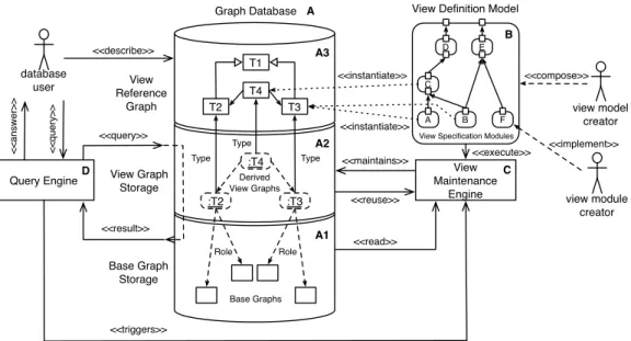
In this chapter, we present the big picture of our approach. Fig. 3.1 depicts the components of our approach. Our approach consists of four main components: a graph database (see A in Fig.3.1, Sec.3.1), a view definition model (see B in Fig.
3.1, Sec. 3.2), a view maintenance engine (see C in Fig.3.1, Sec.3.3), and query engine (see D in Fig.3.1, Sec.3.4). In the following sections, we describe the role of each component by mapping the derived requirements to these components.
Graph Database View Graph Storage Base Graph Storage <<maintains>> :T2 :T3 :T4 Derived View Graphs Base Graphs Role <<reuse>> View Reference Graph T1 T2 T3 T4 Type Type Type Role Query Engine View Maintenance Engine <<read>> database user <<q u e ry>> <<a n sw e r>> view model creator A B F C E D <<compose>>
View Definition Model
<<triggers>>
view module creator
<<implement>> View Specification Modules
<<execute>> <<instantiate>> <<instantiate>> <<query>> <<result>> <<describe>> A B C D A1 A2 A3
3.1. Graph Database
3
.
1
. Graph Database
Our notion of agraph databaseconsists of three parts: a base graph storage (see A1
in Fig.3.1), a view graph storage (see A2 in Fig. 3.1), and view reference graph (see A3in Fig.3.1). According to definition3 a graph database is a set of graphs that are distinguished into base graphs (see definition 4) and view graphs (see definition5). Base graphs are stored by thebase graph storage, while view graphs derived from these base graphs and other view graphs are stored by theview graph
storage. View graphs consist of annotations that mark matches of graph patterns
in base graphs and view graphs (cf.R1a)withoutcopying subgraphs that match a graph pattern to view graphs. Furthermore, base graphs and view graphs consist of a reference graph (see definition4and5). We neglect the reference graph of base graphs in Fig.3.1. For example, the reference graph of source code describes that the abstract syntax graph consists of classes, attributes, references, methods, etc. The reference graph of view graphs is depicted asview reference graphon top of the graph database. Theview reference graphdescribes which kinds of nodes and edges are part of derived view graphs.
Container : Class Component : Class children : Field Container : CompilationUnit Component : CompilationUnit list : OneToN-Assocation generalization : Generalization composite : Composite : OneToNAssociation : Field : Classifier : SuperClass : SubClass : Generalization : Composite : Component namespace : Namespace reference : Classifier argument : TypeArgument type : QualifiedType
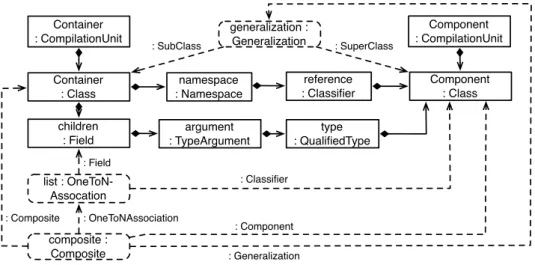
Figure3.2.:View graph about Composite design patterns according to our running example
According to our running example, the view reference graph describes that view graphs about software design patterns consists of nodes that, e.g., describe the occurrences of Composite design patterns, and consists of edges that, e.g., describe
which nodes represent the Container respectively Component class within the Composite software design pattern. Fig.3.2shows a view graph about Composite software design patterns. Solid rectangles and lines denote an excerpt of the base graph. Dashed rectangles and lines denote an excerpt of the derived view graph and depict annotations that mark matches of graph patterns in base graphs and/or view graphs. Fig.3.2depicts a detected Composite software design pattern in Java AWT. TheCompositeannotation (dashed rounded rectangle) denotes the detected Composite design pattern and depends on theGeneralizationannotation and
OneToN-Associationannotation referenced by roles (dashed lines). The
General-izationannotation describes a specialization of theComponentclass asContainer
class. TheOneToN-Associationannotation describes that thechildrenfield is a to-many association with theComponentclass as target type.
3
.
2
. View Definition
View graphs are derived with the help of a view definition model that consists of view definition modules. A view definition module (Sec. 3.2.1) specifies the graph patterns used to derive view graphs. Aview definition model(Sec.3.2.2) describes the interplay of multiple dependent view definition modules, i.e., how dependent view definition modules reuse view graphs derived by other view definition modules.
3.2.1. View Definition Module
A view definition module (view module for short) implements a graph query by
enabling the view module creator to specify graph patterns (cf.R1). View modules employ graph pattern matching to findallmatches of the specified graph pattern. As result, for each match of the graph pattern the view definition module creates an annotation that marks the match in base graphs and view graphs instead of copying matched subgraphs to view graphs (cf. R4c). The annotation references
allnodes that participate in a certain match. Therefore, annotations are considered as markers for graph pattern matches. Thus, a view graph consists of a set of annotations.
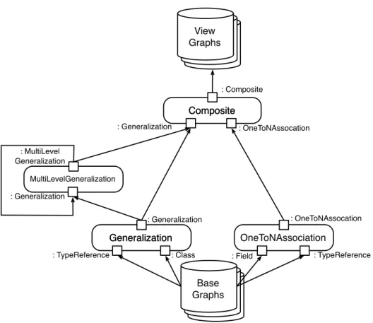
According to our running example as depicted by Fig. 3.3, view modules exist that create view graphs about generalizations, multi-level generalizations, one-to-N associations, and Composite design patterns. For that purpose, the Generaliza-tionview module describes that it usesClassandTypeReferencenodes in base graphs to create a view graph about generalizations. The MultiLevelGeneraliza-tionview module describes that it uses view graphs about generalizations as well
3.2. View Definition
as multi-level generalizations to derive view graphs about multi-level generaliza-tions. Moreover, theOnetoN-Associationmodule defines that it usesFieldand
TypeReferencenodes to create a view graph about one-to-N associations. The
Com-positeview module defines that it uses view graphs aboutGeneralizations and
OnetoN-Associations to create a view graph about Composite software design
patterns. Generalization Generalization OneToNAssociation : OneToNAssocation Composite Composite : Generalization : OneToNAssocation : Generalization : Composite : MultiLevel Generalization MultiLevelGeneralization : Generalization Base Graphs Base Graphs Base Graphs Base Graphs Base Graphs View Graphs
: Class : Field : TypeReference
: TypeReference
Figure3.3.:Simplified view definition model according to our running example
3.2.2. View Definition Model
The view definition model (view model for short) describes the interplay of view
modules, e.g., which view module uses which information derived by dependency view module (cf.R1b, R1c, andR2). Therefore, a view model is a directed cyclic
graph of dependent view modules that is created by view model creators. Note that cyclic dependencies are permitted to support recursion.
According to our running example as depicted by Fig.3.3, the view model de-scribes that theCompositeview module uses the view graphs created by the
Gener-alization,MultiLevelGeneralizationview module andOneToN-Association
module. Note that a view module can reuse multiple view graphs of the same kind. For example, theCompositeview module can use view graphs about gen-eralizations and multi-level gengen-eralizations, because Composite software design patterns that use multi-level generalization are an implementation variant of the Composite design pattern as defined by Gamma et al. [23]. In our running example depicted by Fig. 3.3, single-level generalizations and multi-level generalizations are derived from base graphs by two separate modules. Note that derived multi-level generalizations are exploited recursively denoted by the dependency from the
MultiLevelGeneralizationmodule to theMultiLevelGeneralizationmodule.
In doing so, theMultiLevelGeneralizationmodule is able to derive additional multi-level generalizations that are composed of other multi-level generalizations.
3
.
3
. View Maintenance Engine
The view maintenance engine (view engine for short) is responsible to keep view
graphs consistent with their base graphs (cf.R3). Initially, the view engine derives the view graphs from the base graphs and other view graphs from scratch. Af-terwards, the view engine employs maintenance procedures to keep derived view graphs up-to-date with respect to their base graphs. For that purpose, the view engine takes the base graphs, already existing view graphs, and the view model with its view modules as input and adds, deletes, or updates annotations within view graphs. We distinguish three basic kinds of view maintenance procedures. All three maintenance procedures support the expressiveness of view models in terms of nested graph conditions and recursion (cf.R2andR5c).
In the following sections, we only outline the supported maintenance modes and give a complete description in Sec.5. We distinguish naive batch mode (Sec.3.3.1), batch mode with preservation (Sec.3.3.2), and incremental mode (Sec.3.3.3).
3.3.1. Naive Batch Maintenance
The naive batch maintenance procedure deletes all view graphs and creates them from scratch. This procedure perform a full recomputation of view graphs, but can be beneficial when the changes made to base graphs are large and, therefore, the
3.3. View Maintenance Engine
additional overhead of the other maintenance procedures may not pay off. Note that annotations, which mark matches of graph patterns, change their identity when they are created from scratch and, thus complicate a post-processing of these annotations. Therefore, graph database users do not desire this naive batch maintenance.
3.3.2. Batch Maintenance with Preservation
The batch maintenance procedure with preservation processes all view graphs completely, but deletes annotations only when necessary. Thus, this maintenance procedure preserves annotations in view graphs that are still consistent with base graphs. The required maintenance steps are derived from the view modules (cf.R5). The maintenance procedure is independent of the employed graph pattern match-ing technology (cf.R5b), because the required maintenance steps are derived from the view module specification as shown by Fig. 3.3. In Sec. 5, we describe the concrete maintenance steps in detail.
3.3.3. Incremental Maintenance
The incremental maintenance procedure processes view graphs only partially. Which parts of the view graphs must be re-processed is derived from the mod-ification information of base graphs. In general, only a small part of the view graphs needs to be re-processed, because heuristically the modified parts of base graphs are often much smaller than the complete base graphs. Thus, the incremen-tal maintenance is in general much more efficient than batch maintenance (cf.R4). Therefore, less time is required to keep view graphs consistent with their base graphs (cf. R4a) in contrast to naive batch maintenance and batch maintenance with preservation. The required maintenance steps are derived from the view mod-ule specifications (cf. R5) and modification information of base graphs to avoid unnecessary maintenance steps (cf. R5a). The modification information of base graphs determine which view modules need to be re-executed to make impacted view graphs consistent with their base graphs. Similar to batch maintenance with preservation, the maintenance procedure is independent of the employed graph pattern matching technology (cf.R5b).
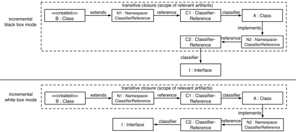
We distinguish two incremental modes to compute the input for view modules when maintaining view graphs. Both modes take the modification information of base graphs into account to derive artifacts and annotations that are required as input by view modules to make derived view graphs consistent with changed base graphs. In incremental black box mode, the artifacts and annotations required by
a view module for maintenance are derived from the view module specification without taking the graph pattern specified within a view module into account. In incremental white box mode, the artifacts and annotations required by a view module for maintenance are derived from the graph pattern specified within the view module. When taking the concrete graph pattern into account the number of artifacts and annotations required as input for view modules can be decreased to reduce the effort of the view module to maintain the derived view graph. The number of required artifacts and annotations can be reduced, because edges be-tween nodes in the graph pattern can be considered to compute relevant artifacts and annotations by only considering artifacts and annotations as relevant when they are reachable via edges that are part of the graph pattern specified within the view module, in contrast to incremental black box mode.
3
.
4
. Query Engine
Thequery engineenables to query base graphs and view graphs, e.g., using a graph
pattern matching language. The concrete query language is not in the scope of this technical report. The query engine is capable of triggering the view mainte-nance when deferred view maintemainte-nance (cf.R3b) is employed to make the view graphs required for answering certain queries consistent with their base graphs. In case immediate view maintenance (cf.R3a) is employed, the view maintenance engine immediately propagates the changes from base graphs to view graphs by (partially) re-executing the view model. Then, the query engine can answer queries without triggering view maintenance, because all changes to base graphs have been propagated to view graphs immediately.
4
. View Definition Approach
In this section, we present our view definition approach that consists of a) a view reference graph that describes the kinds of interrelationships between nodes in base graphs and view graphs (Sec.4.1), b) dependent view modules (Sec.4.2) that compute matches for graph queries (Sec.4.3), and c) a graph pattern language that enables to refer effectively to nodes that are already part of other view graphs (Sec.
4.4). Furthermore, we describe the syntax of derived view graphs (Sec. 4.5) and how nested conditions can be mapped to view models (Sec.4.6). Finally, we discuss the fulfillment of the requirements that we describe in Sec.2.2.
4
.
1
. View Reference Graph
When creating view graphs over base graphs one must be aware of which kinds of nodes in base graphs and view graphs are processed to derive view graphs and which kind of information is represented within these view graphs. For that purpose, our approach enables to model a view reference graph (see definition5) that describes which kinds of nodes in base graphs and view graphs are considered by view graphs that represent a certain kind of information (cf.R1a). Note that the view reference graph does not specify the graph query that defines the content of view graphs.
The left side of Fig. 4.1 shows our view reference graph metamodel, which defines the concepts ofArtifactTypes,AnnotationTypes, andRoleTypes, which can be used to describe view reference graphs.
An ArtifactTypedescribes the type of a node in a base graph and consists of
a name. We refer to a node in a base graph as artifact of a certain artifact type. Furthermore, a hierarchy ofArtifactTypes exists denoted by thesubTypes(resp.
superType) reference.
An AnnotationTypedescribes the type of a node in a view graph and consists
of a name. We refer to nodes in view graphs as annotations of a certain
view graphs. Therefore, an annotation type describes which kind of information is represented by an annotation.
ARoleTypedescribes which kind of artifact in a base graph or annotation in a
view graph participates in an annotation. ARoleTypedescribes in which role (resp. semantic) an artifact or annotation acts when marked by an annotation of a certain annotation type. Therefore, eachRoleTypereferences either anArtifactTypeor
AnnotationTypeto describe the type of the artifact or annotation that is annotated
(cf.AnnotatedTypein Fig.4.1).
Note thatsubTypes(resp.superTypes) of AnnotationTypes exist and that
Ro-leTypes are inherited to annotation sub types. Furthermore, annotation sub types
can consist of additional role types.
<<AnnotationType>> Generalization <<AnnotationType>> OneToNAssociation <<AnnotationType>> ArrayField <<AnnotationType>> ListField <<AnnotationType>> Composite <<ArtifactType>> Class <<ArtifactType>> Field <<AnnotationType>> DesignPattern AnnotatedType NamedElement String name ArtifactType AnnotationType RoleType annotationType roleTypes * * 1 * annotatedType roleTypes superType subTypes 1 * <<RoleType>> SuperClass <<RoleType>> SubClass <<RoleType>> Generalization <<RoleType>> Association <<RoleType>> Classifier <<RoleType>> Field View Reference Graph Meta-Model View Reference Graph in Concrete Syntax
<<RoleType>> Component <<RoleType>> Composite superType subTypes * 1 <<ArtifactType>> ConcreteClassifier <<ArtifactType>> Member
Figure 4.1.: View reference graph metamodel (left) and view reference graph in concrete syntax according to our running example (right)
The right side of Fig. 4.1 shows our running example in concrete syntax. As concrete syntax we use Unified Modeling Language (UML) class models with stereotypes. Artifact types, annotation types, and roles types are labeled with the stereotypes«ArtifactType»,«AnnotationType», and«RoleType». According to our running example, abstract syntax graphs of source code contain among others
ConcreteClassifiers such asClasses. Furthermore, such abstract syntax graphs
containMembers ofClasses such asFields. TheCompositeannotation type con-sists of the role types Component and Composite, which reference the artifact
typeClass to express that a Composite annotation references one class that acts
as component class and one class that acts as composite class. Furthermore, the
Compositeannotation type consists of the role typesGeneralizationand
Associ-ation, which reference theGeneralizationandOneToNAssociationannotation
general-4.2. View Modules
izations and one-to-N associations. TheGeneralizationannotation type consists of the role types SuperClass and SubClass, which describe that generalization annotations reference one super class and one sub class. TheOneToNAssociation
annotation type consists of the role typesFieldandClassifierthat describe which field acts as one-to-N association and which type this field has. The ListField
andArrayField annotation types are specializations of theOneToNAssociation
annotation type and denote whether an association is implemented using a list or array data structure. TheFieldrole type is inherited from theOneToNAssociation
annotation type to theListFieldandArrayFieldannotation type.
4
.
2
. View Modules
Our approach consists of view modules, which instantiate the view reference graph. View modules (modules for short) execute graph queries and store the query results in terms of annotations in view graphs. According to definition8, graph queries are implemented as graph patterns. We do not make restrictions which graph pattern matching approach is employed within these modules.
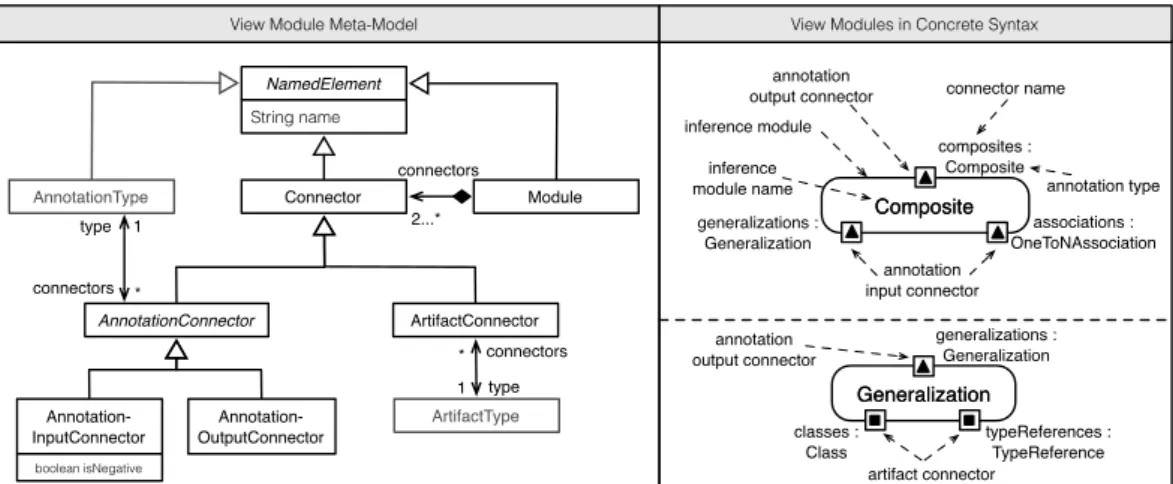
The left side of Fig.4.2shows the view module metamodel. EachModuleconsists of at least twoConnectors, i.e. one input connector and one output connector. We distinguish Connectors into AnnotationConnectors and ArtifactConnectors.
ArtifactConnectors are input connectors, which consume artifacts of a certain
ArtifactTypefrom base graphs. Note that multipleArtifactConnectors of
dif-ferent modules can consume artifacts of the same ArtifactType.
Annotation-Connectors either consume or provide annotations of a certainAnnotationType.
Therefore, we distinguishAnnotationConnectors into AnnotationInputConnec-tors andAnnotationOutputConnectors.AnnotationInputConnectors are input connectors and consume annotations.AnnotationOutputConnectors are output connectors and provide annotations. Note that multipleAnnotationConnectors of different modules can consume and provide annotations of the same Annotation-Type. Furthermore,AnnotationInputConnectors can be negative (cf.isNegative
attribute ofAnnotationInputConnectorclass). A negative
AnnotationInputCon-nectorstates that annotations of the annotation type as specified by the annotation
input connector are used in negative manner within the view module.
The right side of Fig. 4.2 shows our running example in concrete syntax. Mod-ulesare depicted as rounded rectangles with the module name in the middle of the rectangle.Connectors are depicted as small rectangles and consist of a name and artifact type or annotation type separated by a colon. ArtifactConnectors are depicted as rectangles with a filled black rectangle in the middle.
Annota-Connector NamedElement String name connectors 2...* Module Annotation-InputConnector Annotation-OutputConnector AnnotationType 1 * type connectors Composite Composite associations : OneToNAssociation generalizations : Generalization composites : Composite annotation output connector annotation type connector name inference module annotation input connector inference module name
View Module Meta-Model View Modules in Concrete Syntax
ArtifactConnector Generalization Generalization generalizations : Generalization classes : Class typeReferences : TypeReference ArtifactType type connectors * 1 artifact connector annotation output connector AnnotationConnector boolean isNegative
Figure4.2.:View module metamodel (left) and view modules in concrete syntax according to our running example (right)
tionConnectors are depicted as rectangles with a filled triangle in the middle.
AnnotationInputConnectors consist of a triangle that points to the module, while
AnnotationOutputConnectors consist of a triangle that points away from the
mod-ule.
The bottom right of Fig.4.2shows theGeneralizationmodule. The
Generali-zationmodule consumes artifacts of the artifact typesClassandTypeReference
via the artifact connectorsclassesandtypeReferencesto produce annotations of the annotation typeGeneralizationthat are provided via the annotation output connectorgeneralizations, afterwards. The top right of Fig.4.2shows the
Com-positemodule. TheCompositemodule consumes annotations of annotation type
Generalization and OneToNAssociation via the annotation input connectors
generalizationsandassociationsto produce annotations of annotation type
Compositethat are provided via the annotation output connectorcomposites.
4
.
3
. View Models
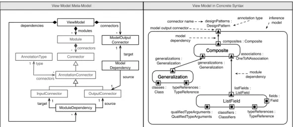
In our approach, view modules and dependencies between view modules constitute a directed cyclic graph and exchange results of graph queries in terms of anno-tations. The left side of Fig.4.3 shows the view model metamodel. AViewModel
contains Modules (see Fig. 4.2), which are connected by ModuleDependencies.
AModuleDependencyconnectsAnnotationOutputConnectors with
4.3. View Models
annotations. Furthermore, a ViewModel consists of ModelOutputConnectors. A
ModelOutputConnectorprovides the overall view graph computed by the
View-Model. For that purpose,ModelDependencies connect
AnnotationOutputConnec-tors withModelOutputConnectors.
Connector connectors * Module InputConnector OutputConnector AnnotationType 1 * type connectors Composite Composite ViewModel ModuleDependency source target ModelOutput Connector modules * connectors * Model Dependency target
source GeneralizationGeneralization
generalizations : Generalization ListField listFields : ListField composites : Composite generalizations : Generalization associations : OneToNAssociation inference model model output connector
designPatterns : DesignPattern model
dependency
connector name annotation type
View Model Meta-Model View Model in Concrete Syntax
classes : Class typeReferences : TypeReference fields : Field typeReferences : TypeReference qualifiedTypeArguments : QualifiedTypeArguments module dependency AnnotationConnector classifiers : Classifiers * dependencies 1 1 1 1
Figure 4.3.: View model metamodel (left) and view model in concrete syntax ac-cording to our running example (right)
The right side of Fig.4.3shows our running example in concrete syntax.
View-Models are depicted as rounded rectangles, which embed Modules. Similar to
AnnotationOutputConnectors of Modules, each ModelOutputConnector is
de-picted as rectangle with a filled triangle pointing away from theViewModeland is labeled with a name and annotation type separated by a colon.ModelDependencies
and ModuleDependencies are depicted as solid lines from
AnnotationOutput-Connectors to ModelOutputConnectors and ModuleOutputConnectors,
respec-tively. The arrow end denotes the dependent connector (resp. module).
ModuleDe-pendencies must connectAnnotationOutputConnectors and
AnnotationInput-Connectors of equal annotation (super) types. Well-formedness considerations of
4
.
4
. View Query Language
Our approach provides a default graph pattern language to enable an easy imple-mentation of graph queries in terms of graph patterns within modules. We refer to this graph pattern language asview query language. Note that also other graph pattern languages can be used.
Module String description RuleObject String name RuleLink EStructuralFeature feature ruleObjects ruleLinks * RuleElement RuleModifier modifier source targets target sources * * 1 1 AnnotationType String name artifactType 1 AnnotationRuleObject AnnotationRoleLink 1 annotationType RoleType ArtifactType EClassifier classifier * 1 roleType
View Query Language Meta-Model
RuleConstraint ConstraintLanguage language String expression constraints * RuleModifier EXIST CREATE NEGATIVE
Figure4.4.:View query metamodel
Fig.4.4shows the metamodel of our view query language. Our view query lan-guage consists ofRuleObjects denoted as solid rectangles and AnnotationRuleOb-jects denoted as dashed rounded rectangles.RuleObjects matchArtifacts in base graphs, whileAnnotationRuleObjects matchAnnotations in view graphs. The label ofRuleObjects andAnnotationRuleObjects consists of a unique name (omitted in Fig.4.5) andArtifactTypeorAnnotationTypeseparated by a colon. Solid edges betweenRuleObjects depictRuleLinks and dashed lines between
An-notationRuleObjects and RuleObjects (resp. AnnotationRuleObjects) depict
AnnotationRoleLinks. The label of RuleLinks denotes the name of an
EStruc-turalFeature(reference), while the label ofAnnotationRoleLinks consists of a
unique name (omitted in Fig.4.5) and role type name separated by a colon.
RuleOb-jects,AnnotationRuleObjects andAnnotationRoleLinks consist of a
RuleMod-ifierthat describes whether anArtifact,Annotation, orRolemust already exist,
must not exist, or will be created. Annotations and Roles that will be created are labeled by ’++’ (Create modifier).Artifacts,Annotations, andRoles that
4.4. View Query Language
mustnotexist are crossed out (Negativemodifier).Artifacts,Annotations, and
Roles that must exist are not labeled (Exists modifier).
ListField f : Field : ListField ++ listClassifier.instanceOf('java.util.List') : QualifiedType Argument : ConcreteClassifier ++ associations : OneToNAssociation Composite generalizations : Generalization : Class : Class : Composite ++ ++ : Field members ++ ++ : Association : Component : Composite : Generalization ++ : Field ++ : Classifier : Generalization : SubRole : OneToNAssociation listFields : ListField composites : Composite Generalization : Class : Class : NamespaceClassifier Reference : Generalization ++ ++ : SuperRole : SubRole ++ generalizations : Generalization target extends : ClassifierReference classifierReferences : SuperRole : Field : ArrayDimension : NamespaceClassifier Reference : ClassifierReference : ConcreteClassifier : ArrayList : Field typeReference classifierReference target : Classifier ++ ++ ++ dimensions lists : ArrayList ArrayList
classes : Class references : TypeReferences
classes : Class dimensions : ArrayDimension classifiers : Classifiers fields : Field : NamespaceClassifier Reference : ClassifierReference : ClassifierReference : NamespaceClassifier Reference typeReference classifierReferences typeArguments typeReference classifier References target fields : Field classifiers : Classifiers references : TypeReferences arguments : QualifiedTypeArgument : Classifier listClassifier : ConcreteClassifier target
View Query Language in Concrete Syntax
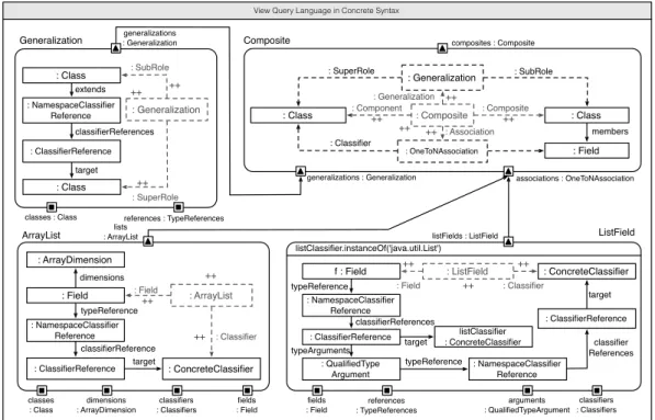
Figure4.5.:Module implementations for our running example (simplified)
Fig. 4.5 shows (simplified) module implementations according to our running example using our view query language. According to our running example, the moduleGeneralizationon top left of Fig.4.5specifies the pattern graph that iden-tifies an inheritance between two classes in an abstract syntax graph (ASG). A chain
ofNamespaceClassifierReferenceandClassifierReferencethat references the
super class of a class defines an inheritance between two classes.
Namespace-ClassifierReferences andClassifierReferences are subtypes of
TypeReferen-ces. Therefore, the module connectors specify thatClasses andTypeReferences are required to identify inheritances in the data graph. When the generalization pattern matches, aGeneralizationannotation is created that references the sub-ordinate class via the role of type SubRole and the superordinate class via the role of typeSuperRole. TheRuleObjectof typeNamespaceClassiferReference
annotation via a role, because they do not act in a role with a certain semantic. However, implicit (invisible) roles between the matched artifacts of type
Namespace-ClassiferReference and ClassifierReference are created, because these
arti-facts are also part of the annotation and must trigger a revision of the
general-izationannotation when they are modified or deleted. As rule of thumb, each
RuleObjectandAnnotationRuleObjectwith Exists modifier that is not
explic-itly referenced by a role is implicexplic-itly referenced by an invisible role that belongs to
theAnnotationRuleObjectwith Createmodifier.
The modulesArrayFieldandListFieldimplement the graph patterns for iden-tifying 1:N references. Both modules create annotations that reference the fields that act as 1:N references and the classifiers that act as the target classifiers of the reference. Both modules implement different graph patterns, but both identify
OneToNAssociations that is the super type of the ArrayField and ListField
annotation types (see Fig.4.1). The Compositemodule specifies how to combine
Generalizationand OneToNAssociation annotations to detectComposite
soft-ware design patterns in an ASG. The Composite module uses Generalization
andOneToNAssociationannotations as context. The super class must be the target
type of an1:N reference and this1:N reference must be a member of the sub class of this super class. Then, the super class acts in aComponentrole and the sub class acts in aCompositerole. Furthermore, theGeneralizationannotation and
OneT-oNAssociationare explicitly referenced via roles, since they are pre-conditions to
identifyCompositedesign patterns and one may want to access these annotations in dependent modules effectively by traversing these role.
Note that due to the view reference graph dependent modules do not need to know the concrete graph pattern implemented by dependency modules and, thus, modules can be considered as black boxes.
4
.
5
. View Graphs
The annotations computed by modules and the dependencies between annotations via roles constitute a directed acyclic graph. The left side of Fig.4.6shows the view graph metamodel. The view graph metamodel depicts thatAnnotations have a certainAnnotationType. Annotations mark matches of graph patterns. Since
An-notationTypes consist ofRoleTypes (see Fig.4.1), eachAnnotationmust consist
ofRoles of certainRoleTypes. EachRole annotates anArtifactorAnnotation
of the correspondingArtifactTypeorAnnotationTypeas described by the Role-Typein the view reference graph (see Fig.4.1). Note that eachModuleknows which
4.6. Mapping Nested Conditions to View Models
annotations it has created and that each annotation knows by whichmodule it
has been created.
View Graph Meta-Model
ArtifactType annotation roles 1 * RoleType AnnotationType AnnotatedElement Artifact Role Annotation roles element 1 * 1 1
1 type type type
*
*
* instances instances
NamedElement
String name
View Graph in Concrete Syntax (detected Composite pattern in Java AWT)
Container : Class Component : Class
children : Field Container.xmi : CompilationUnit Component.xmi : CompilationUnit awt : Package list : ListField generalization: Generalization composite : Composite : 1ToNAssociation : Field : Classifier : SuperClass : SubClass : Generalization : Composite : Component instances Module * 1 annotations module
Figure 4.6.: View graph metamodel (left) and view graph in concrete syntax ac-cording to our running example (right)
The right side of Fig.4.6 depicts the concrete syntax of annotations, roles, and artifacts according to our running example.Annotations are depicted as dashed rounded rectangles with the annotation name and annotation type in the middle of the rectangle separated by a colon.Roles are shown as dashed lines with the name of itsRoleTypeattached. The arrow end ofRoles denotes the annotatedArtifact
orAnnotation. Solid rectangles depictArtifacts with the name and artifact type
separated by a colon in the middle of the rectangle. Solid lines betweenArtifacts denote a containment hierarchy ofArtifacts. The arrow denotes the child Arti-fact, while the rhombus denotes the parentArtifact. We neglect other references betweenArtifacts in base graphs, if they are not important for illustrating our running examples.
4
.
6
. Mapping Nested Conditions to View Models
Graph conditions are graph patterns that, if satisfied, let the graph condition become true. We distinguish graph conditions into positive graph conditions and negative graph conditions. A positive graph condition becomes true if the graph pattern is satisfied. A negative graph condition becomes true if the graph pattern isnotsatisfied.
A nested graph condition is a boolean formula that consists of graph conditions. If c is a graph condition, then also ¬c is a graph condition. Furthermore, if ci
is a graph condition, then _ci and ^ci with index set i 2 I are (nested) graph
conditions.
In the following sections, we describe how nested graph conditions can be mapped to view models. We describe the mapping of overlapping graph conditions (Sec.4.6.1), conjunctions (Sec.4.6.2), disjunctions (Sec.4.6.3), positive and negative graph conditions (Sec.4.6.4) as well as recursion (Sec.4.6.5) to view models.
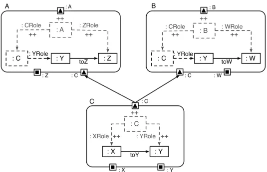
4.6.1. Mapping Overlapping Graph Conditions
Graph conditions are specified within view modules. A graph condition can be part of multiple more complex graph conditions. Therefore, graph conditions can overlap. The overlapping parts of graph conditions should be mapped to a single view module, because shared graph conditions should be matched only by one view module. Then, dependent view modules can reuse matches of these graph conditions to avoid unnecessary additional computations of matches for the same graph pattern. The reuse of matches for graph patterns is mapped to multiple outgoing module dependencies with different view modules as target.
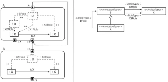
Fig. 4.7 shows graph condition C(x,y) with x 2 X and y 2 Y. The graph
condition C(x,y) is specified as directed edge toY between artifacts of type X
andY. The graph condition C(x,y)is reused by graph condition A(C(x,y),z) ⌘
C(x,y)^A0(y,z)withz 2 Z and B(C(x,y),w) ⌘ C(x,y)^B0(y,w) withw 2 W.
The graph condition A0(y,z)is specified as directed edge toZ between artifacts
of type Y andZ. The graph condition B0(y,w)is specified as directed edge toW
between artifacts of typeYandW.
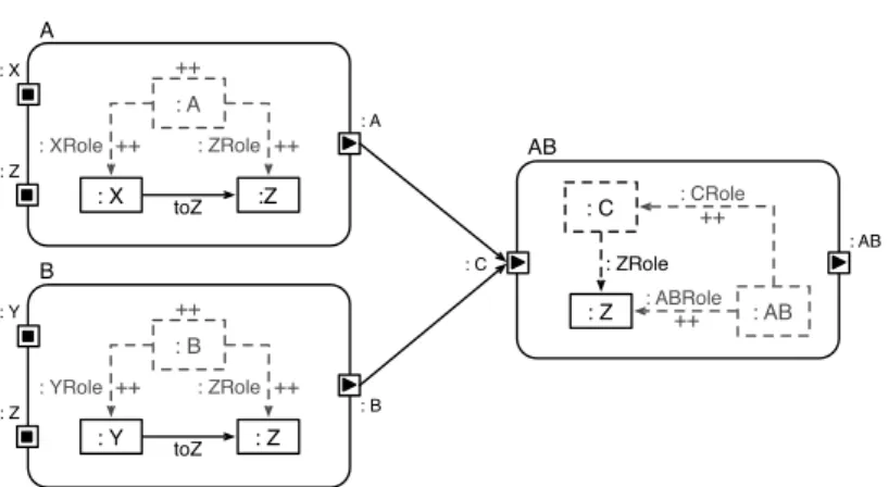
4.6.2. Mapping Conjunctions
When at least two graph conditions are combined in terms of a conjunction, three general options exist to express this conjunction in view models. Fig. 4.8 shows three alternatives for encoding the graph condition AB(x,y,z)⌘ A(x,y)^B(y,z)
with x 2 X, y 2 Y, and z 2 Z. The graph condition A(x,y) is specified as an
edge toY between artifacts of type X and Y, while graph condition B(y,z) is specified as an edgetoZbetween artifacts of typeYandZ. Either the conjunction is specified within one single view module AB (see Fig. 4.8 top left), is split up into two sequential view modules A and AB0 (see Fig. 4.8 top right), or is split
up into three view modules A, B, and AB00 (see Fig.4.8 bottom). The single view
4.6. Mapping Nested Conditions to View Models A : A ++ : A : C : Z : Y : Z : ZRole : YRole ++ ++ toZ B : B ++ : CRole : B : C : W : Y : W : WRole : YRole ++ ++ toW : C : CRole : C C : X : C ++ : XRole : C : X : Y : Y : YRole ++ ++ toY
Figure4.7.:Overlapping conditions: The graph conditions specified by view mod-ule AandBoverlap in graph conditionC
pattern. The sequential view module approach specifies the graph conditionA(x,y)
and graph condition AB0(A(x,y),z) ⌘ AB in two separate modules. The actual
conjunction of graph conditionA(x,y)and B(y,z)is specified in the view module AB0. Note that this alternative could search for the graph condition B(y,z) first
and a view module BA could specify the conjunction of both graph conditions
BA(x,B(y,z))⌘ AB, afterwards. The alternative with the three view modules A,
B and AB00 specifies the graph conditions A(x,y) and B(y,z)separately and the
actual conjunction AB00(A(x,y),B(y,z)) ⌘ AB is specified by the view module
AB00.
4.6.3. Mapping Disjunctions
When at least two graph conditions are combined in terms of a disjunction, one single mapping exists to express this disjunction in view models. Fig.4.9shows the mapping for the graph condition AB(w,z) ⌘ A(w,z)_B(w,z)with w 2 W and
z2 Z. The graph condition A(w,z)is specified as an edgetoZbetween artifacts of
type X✓W andZ, while the graph conditionB(w,z)is specified as an edge toZ