VbTrace: Using View-based and Model-driven
Development to Support Traceability in
Process-driven SOAs
Huy Tran and Uwe Zdun and Schahram DustdarDistributed Systems Group Information System Institute Vienna University of Technology, Austria
htran|zdun|[email protected]
Abstract. In process-driven, service-oriented architectures, there are a number of important factors
that hinder the traceability between design and implementation artifacts. First of all, there are no explicit links between process design and implementation languages not only due to the differences of syntax and semantics but also the differences of granularity. The second factor is the complexity caused by tangled process concerns that multiplies the difficulty of analyzing and understanding the trace dependencies. Finally, there is a lack of adequate tool support for establishing and maintaining the trace dependencies between process designs and implementations. We present in this article a view-based, model-driven traceability approach that tackles these challenges. Our approach supports (semi-)automatically eliciting and (semi-)formalizing trace dependencies among process development artifacts at different levels of granularity and abstraction. A proof-of-concept tool support has been realized, and its functionality is illustrated via an industrial case study.
1
Introduction
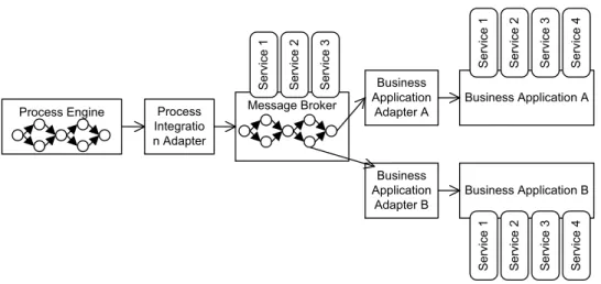
In a process-driven, service-oriented architecture (SOA) the notion of process is central [16]. A typical process consists of a control flow and a number of tasks to accomplish a certain business goal. Each task performs either a service invocation or a data processing task. Processes can be deployed in a process engine for enactment and monitoring. Figure1illustrates a small-scale process-driven SOA[16]. Process engines access service-based message brokers, e.g., offered by Enterprise Service Buses, via service-based process integration adapters. Service-based business application adapters are used as bridges between the brokers and back-end components, such as databases or legacy systems.
Business processes are often designed in highly abstract and primarily notational modeling languages such as BPMN [42], EPC [20], or UML Activity Diagrams [39]. Process designs are suitable for business experts to represent domain-and business-oriented concepts domain-and functionality but mostly non-executable because many technical details are missing. Thus, IT experts necessarily need to be involved in the process development to transform the process designs into executable specifications. For example, IT experts can translate abstract, high-level concepts of process designs into concrete, fine-grained elements in executable process languages such as BPEL [35] and specify the process interfaces in Web Service Description Language (WSDL) [57]. Additional deployment configurations might also need to be defined in order to successfully deploy and execute the implemented processes.
Understanding trace dependencies between process design and implementation is vital for change impact analysis, change propagation, documentation, and many other activities [49]. Unfortunately, artifacts created during the
Process Integratio n Adapter Message Broker Business Application Adapter A Business Application Adapter B Business Application A Business Application B Process Engine Se rvi ce 1 Se rvi ce 2 Se rvi ce 3 Se rvi ce 4 Se rv ice 1 Se rv ice 2 Se rv ice 3 Se rv ice 4 Se rvi ce 1 Se rvi ce 2 Se rvi ce 3
Figure 1: Illustrative small-scale process-driven SOA
process development life cycle likely end up being disconnected from each other. This impairs the traceability of development artifacts. We identify the following important factors that complicate the establishing and maintenance of trace dependencies:
• There are no explicit links between process design and implementation languages. This lack of dependency links is caused by not only syntactic and semantic differences but also the difference of granularity as these languages describe a process at various levels of abstraction.
• A substantial complexity is caused by tangled process concerns. Either the process design or implementation comprises numerous tangled concerns such as the control flow, data processing, service invocations, transac-tions, fault and event handling, etc. As the number of services or processes involved in a business process grows, the complexity of developing and maintaining the business processes also increases along with the number of invocations, data exchanges, and cross-concern references, and therefore, multiplies the difficulty of analyzing and understanding the trace dependencies.
• There is a lack of adequate tool support to create and maintain trace dependencies between process designs and implementations.
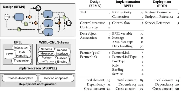
To illustrate the aforementioned factors we use the well-known Travel Booking process [18]. Figure2shows the process development scenario from design to implementation and deployment. We summarize the statistics of the complexity in terms of the number of elements as well as their dependencies in Table??. Even though the syntactic
and semantic differences are omitted in Figure2, the elements represented in executable process languages (here: BPEL and WSDL) are more concrete and of much finer granularity than the design counterparts (here expressed in BPMN). Practically, abstract, high-level model elements are often described or implemented by one or many technology-specific elements. For instance, aData Objectin BPMN is often represented by the corresponding variable in BPEL and the message type from WSDL or the XML Schema type. In addition, some artifacts which are necessary for describing specific features in process implementation or for successfully deploying the process have no corresponding elements in the process design. For instance, there are no corresponding design concepts or elements for the correlation of service invocations in BPEL, service bindings and service endpoints in WSDL, to name but a few. Existing process development approaches or tools merely support the stakeholders in importing, parsing, validating, and referencing elements between languages of the same level of abstraction, for instance, between BPEL, WSDL, and XML Schema, but have no support for cross references between process designs and implementations.
Interaction Data Handling Transaction
BPEL
Message InterfaceService Schema WSDL+XML Schema Service Binding Flow Partner LinkTypes
Process descriptors Service endpoints
Design (BPMN)
Implementation (WSBPEL)
Deployment configuration
Design Implementation Deployment
(BPMN) (BPEL) (PDD)
Task 7 BPEL activity 13 Partner Reference 5
Correlation 7 Endpoint Reference 4 Control structure 3 Control flow 12 Service Reference 5 Control edge 11
Data object 3 BPEL variable 10
Association 11 Message 11
XML data type 11 Data handling 30
Partner (pool) 6 PartnerLink 5
Partner link 9 PartnerLinkType 5
PortType 5
Role 5
Binding 4
Service 4
Total element: 19 Total element 85 Total element 14
Dependency 31 Dependency 104 Dependency 20
Cross-concern 20 Cross-concern 49 Cross-concern 20
Figure 2: The Travel Booking process development (left) and the complexity and dependency statistics (right) The complexity caused by numerous tangled process concerns such as the control flow, service and process interac-tions, data handling, transacinterac-tions, and so forth, hinders the understanding and analyzing of trace dependencies. Table??also shows the statistics of the cross-concern dependencies of process design (20/31), process
implementa-tion (49/104), and deployment configuration (20/20). These numbers mean: In order to thoroughly understand or
analyze a certain concept of either a process design or an implementation, the developer has to go across numerous dependencies between various concerns, some of which are even not suitable for the developer’s expertise and skills. We present a view-based, model-driven traceability approach that supports stakeholders in (semi-)automatically creating and maintaining traceability between process designs and implementations and/or deployment configura-tions. In the context of this article, BPMN[42], a standard for business process modeling, is used as a representative example of a process design language, whilst BPEL[35] and WSDL[57], which are very popular process/service modeling descriptions used by numerous companies today, are used as representative examples for languages for implementing executable processes. Although establishing trace dependencies alone is not sufficient for tasks like change impact analysis or change propagation, it crucially lays the foundation for any such tasks. In this sense, our approach presented in this article is the initial effort that overcomes the aforementioned challenges to support (semi-)automatically eliciting as well as (semi-)formalizing trace dependencies among model artifacts in model-driven development (MDD) at different levels of granularity and abstraction. The (semi-)formalization of the trace dependencies is one of the features needed for the interoperability of tools utilizing them.
In our approach, we exploit the notion of views and the model-driven stack introduced in our previous work [52,53] in order to separate process representations (e.g. process designs or implementations) into different (semi-)formalized view models. In this way, stakeholders can be provided with tailored perspectives by view integration mechanisms [52,53] according to their particular needs, knowledge and experience. This is a significant step toward the support of adapting process representations and trace relationships to particular stakeholder interests. Additionally, view models are also organized into appropriate levels of abstraction: high-level, abstract views are suitable for business experts whilst low-level, technology-specific views are mostly used by IT experts. Given these levels of abstraction, process designs are adequately aligned with the abstract view models, and the implementation counterparts are lined up with the technology-specific view models. This can be done in a (semi-)automatic manner using the view-based
reverse engineering approach described in [54]. Such mappings produce trace dependencies between designs and the view models, and between the view models and the source code that implements the processes. These dependencies are parts of the traceability meta-model which is the key component of our traceability approach. Moreover, the traceability meta-model also supports stakeholders in capturing intrinsic dependencies between view models and view elements.
This article is organized as follows. In Section2we briefly introduce the View-based Modeling Framework (VbMF) [52,53]. Next, Section3presents our view-based, model-driven traceability approach along with the details of the traceability meta-model. A CRM Fulfillment process from an industrial case study is exemplified to illustrate our traceability approach and the realization of the approach in Section4. Then Section5discusses related work. Finally, Section6summarizes our main contributions.
2
View-based modeling framework for process-driven SOAs
Core Model FlowView Model CollaborationView Model InformationView Model BpelCollaborationView Model BpelnformationView Model Technology-specific Layer Abstract Layer TransactionView Model
extends extends extends
extends
horizontal dimension
mastering the complexity of tangled process concerns
vertical dimensi o n bridging abs trac tion levels BpelFlowView Model
extends extends extends
Figure 3: Overview of the View-based Modeling Framework ([17,52,53])
In this section, we briefly introduce the View-based Modeling Framework (VbMF) [52,53] that is the foundation of our traceability approach described in the next section. VbMF exploits the notion of views to separate the various process concerns in order to reduce the complexity of process-driven SOA development and enhance the flexibility and extensibility of the framework. VbMF offers a number of modeling artifacts, such as view models and view instances (or views for short) organized in two levels of abstraction (see Figure3). Each view embodies a number of view elements and their relationships that represent a business process from a particular perspective. View elements and their relationships are precisely specified by a view model. In other words, a view model is a (semi)-formalization of a particular process concern and the views conforming to that view model are concrete instances of the process concern.
VbMF initially provides three foundational (semi-)formalizations for representing a business process which are the FlowView, CollaborationView and InformationView models. The FlowView model describes the orchestration of process activities, the CollaborationView model specifies the interactions with other processes or services, and the InformationView model elicits data representations and processing within processes as well as messages exchanges. However, VbMF is not merely bound to these view models but can be extended to capture other concerns, for instance, human interaction [17], data access and integration [30], transactions, and fault and event handling [52]. VbMF view
models are derived from fundamental concepts and elements of the Core model. Therefore, these concepts of the Core model are the extension points of the view-based modeling framework [52,53]. In our traceability approach, we exploit this feature of the VbMF Core model to derive trace dependencies between different views and between views and view elements.
In addition, VbMF introduces a model-driven stack which is a realization of the model-driven development (MDD) paradigm [12,51]. The model-driven stack separates the view models into abstract and technology-specific layers. In this way, business experts, who mostly work with the high level view models, can better capture, manipulate, and analyze domain- and business-oriented concepts and knowledge as the technical details have been abstracted away. For specific technologies, such as BPEL and WSDL, VbMF provides extension view models which add details to the abstract view models that are required to depict the specifics of these technologies [52,53]. These extension views belong to the technology-specific layer shown in Figure3.
Process Description Language Syntax &
Semantics View Instance View Model Process Descriptions (BPEL, WSDL, XML Schema, etc.) Schematic Executable Code Reverse engineering
tool-chain Forward engineering tool-chain View Interpreter Code Generator View/Instance Editor generates creates, extends uses integrates uses generates produces based on defined in interprets based on
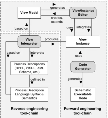
Figure 4: VbMF forward and reverse engineering tool-chains
The view models and view instances are manipulated via a number of components provided in VbMF (see Figure4). TheView/Instance Editorsare derived from the VbMF view models. Using these editors, a new view model can be developed from scratch by deriving from the Core model, or an existing view model can be extended with some additional features to form a new view model. Moreover, these editors also support stakeholders in creating new view instances or editing existing instances. Last but not least, the editors enables stakeholders to integrate relevant view instances in order to produce a richer view or a more thorough view of a certain business process [52,53].Code Generatorsuse the technology-specific view instances to generate executable code. Before generating outputs, the code generators validate the conformity of the input views against the corresponding view models.View Interpreters
are leveraged to extract views from legacy process descriptions. These components of VbMF shape the forward engineering and reverse engineering tool-chains for process-driven SOA development.
these instances are manipulated or refined down to their lower level counterparts, the technology-specific view instances. TheCode Generatorsuses the technology-specific view instances to produce schematic process code and/or necessary configuration code. In our traceability approach,View/Instance EditorsandCode Generatorsneed to be extended such that they can automatically establish trace dependencies between view models, between view models and view elements, and between different view elements. The generated schematic code might need some manually written code (so-called individual code) to fulfill a certain business logic [51]. Our approach supports developers in establishing and maintaining those relationships via the traceability meta-model.
In the reverse engineering tool-chain, theView Interpreterstake as input legacy process descriptions and extract more appropriate representations, i.e. process views, out of the legacy code. These process views can be used in the forward engineering tool-chain for re-generating certain parts of the process code. During the reverse engineering process, high-level, abstract views and low-level, technology-specific views can be recovered from the existing code. This way, the reverse engineering approach helps stakeholders to get involved in process re-development and maintenance at different abstraction levels [54]. TheView Interpretersplay a central role in the reverse engineering tool-chain. In the scope of this article we extend theView Interpretersfrom [54] for transforming process implementations in terms of BPEL and WSDL code, or process deployment descriptors in XML, onto VbMF technology-specific views. Other
View Interpretersare developed to map process designs in terms of BPMN diagrams onto VbMF abstract views. Relevant trace dependencies generated by these mappings are tracked and recorded in the traceability meta-model, the (semi-)formalized representation of trace dependencies in our approach.
To summarize, the view-based modeling approach realized in VbMF is the foundation for dealing with the complexity of various tangled concerns in business processes, i.e., the second challenge we mentioned above in Section1. Moreover, the model-driven stack in VbMF is the basis to organize view models into adequate levels of abstraction, and therefore, to deal with the differences of granularity at these abstraction levels. In the next section, we present our key contributions, the view-based, model-driven traceability approach, along with the traceability meta-model and the supporting mechanisms and tools for establishing and maintaining the trace dependencies.
The concepts and mechanisms mentioned above have been realized as a view-based modeling framework [52–54]. In this modeling framework, view models are based on Eclipse Ecore, a MOF-compliant meta-model [9]. The code generation templates have been developed using openArchitectureWare’s XPand and Xtend languages [43]. The VbMF tooling also provides a number of tree-based view editors for manipulating view instances. These tree-based view editors are extended for producing corresponding relationships between views and view elements and used for illustration purposes in this article.
3
View-based, model-driven traceability framework
3.1
Fundamentals of the view-based, model-driven traceability framework
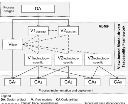
In the previous section we introduce the view-based modeling framework (VbMF) which supports stakeholders in modeling and developing processes using various perspectives which are tailored for their particular needs, knowledge, and skills at different levels of abstraction. We propose in this section our view-based, model-driven traceability approach (VbTrace) in terms of a traceability framework which is an additional dimension to the model-driven stack of VbMF (see Figure5).
VbTrace supports stakeholders in establishing and maintaining trace dependencies between the process designs and implementations (i.e., process code artifacts) via VbMF. The trace dependencies between process design and abstract, high-level views and those between low-level, technology-specific views and code artifacts can be automatically derived during the mappings of process designs and implementations into VbMF views using an extended version
Vflow V1abstract V1 technology-specific Vi ew -ba sed Mo d el -dri ve n T ra cea bi lity F ra mew or k V2abstract V3 technology-specific
Process implementation and deployment
CA1 CA2 CA3 CA4 CA5
DA Process
designs
Legend
DA: Design artifact V: View models CA:Code artifact
Intrinsic trace dependencies Generated trace dependencies VbMF
V2 technology-specific
Figure 5: View-based, model-driven traceability approach as an additional dimension of VbMF
of the view-based reverse engineering approach presented in [54]. These trace dependencies are represented by the solid arrows in Figure5. The relationships between a view and its elements are intrinsic whilst the relationships between different views are established by using the name-based matching mechanism for integrating views [52,53]. These relationships are indicated in Figure5by dashed lines because they are merely derived from the view models and mechanisms provided by VbMF [52,53]. Therefore, in this article we will concentrate more on the former kind of trace dependencies, i.e., the trace dependencies between process designs and implementations and view models. Nonetheless, the case study in Section4will illustrate a complete consolidation of the aforementioned kinds of trace dependencies as a whole. In the subsequent sections, we present the view-based traceability meta-model that is a (semi-)formalization of trace dependencies between process development artifacts. Based on the traceability meta-model, we extend and use the components and mechanisms provided by VbMF to shape a view-based, model-driven traceability framework that supports stakeholders in (semi-)automatically establishing and maintaining the corresponding trace dependencies.
3.2
View-based traceability meta-model
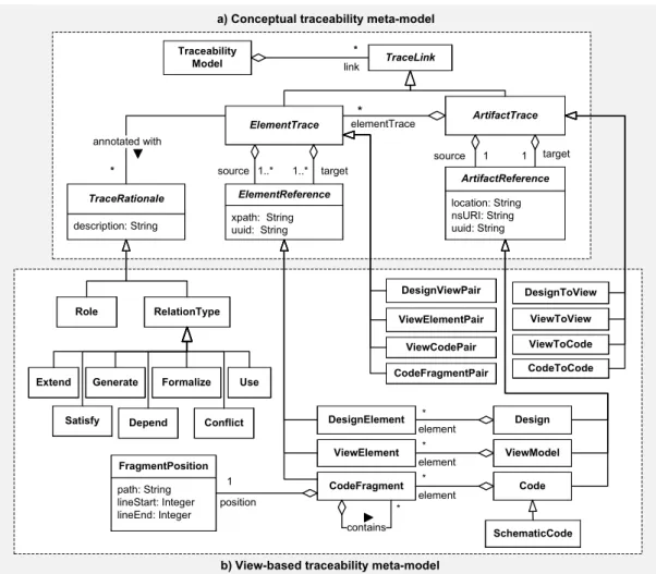
At the heart of VbTrace, we devise a traceability meta-model that provides concepts for precisely eliciting trace dependencies between process development artifacts. This traceability meta-model is designed to be rich enough for representing trace relations from process design to implementation and be extensible for further customizations and specializations. Figure6(a) shows the conceptual overview of the meta-model that defines aTraceabilityModel
containing a number ofTraceLinks. There are two kinds ofTraceLinksrepresenting the dependencies at different levels of granularity:ArtifactTracesdescribing the relationships between artifacts such as BPMN diagrams, view models, BPEL and WSDL files, and so on;ElementTracesdescribing the relationships between elements of the same or different artifacts such as BPMN notations, view elements, BPEL activities, WSDL messages, XML Schema elements, and so forth. The source and target of anArtifactTraceareArtifactReferenceseach of which consisting of either the location path, the namespace URI, or the UUID1of the corresponding artifact. An artifact may contain a
Traceability Model 1..* source ElementTrace xpath: String uuid: String ElementReference * link ArtifactTrace elementTrace* target 1..* description: String TraceRationale * annotated with TraceLink location: String nsURI: String uuid: String ArtifactReference target 1 1 source Code element * element * SchematicCode CodeFragment element * * contains Formalize Generate Extend Use path: String lineStart: Integer lineEnd: Integer FragmentPosition position 1 DesignElement ViewElement Design ViewModel ViewToView ViewToCode DesignToView CodeToCode ViewElementPair DesignViewPair ViewCodePair CodeFragmentPair
a) Conceptual traceability meta-model
b) View-based traceability meta-model
RelationType Role
Depend Conflict
Satisfy
Figure 6: VbTrace meta-models: (a) the conceptual traceability meta-model, and (b) the view-based, model-driven traceability meta-model
number of elements described by theElementReferencemeta-class. EveryElementReferenceholds either an XPath expression [56] or a UUID which is a universal reference of the underlying actual element.
EachElementTracemight adhere to someTraceRationalesthat comprehend the existence, semantics, causal relations, or additional functionality of the link. TheTraceRationaleis open for extension and must be specialized later depending on specific usage purposes, for instance, for reasoning on trace dependencies concerning the traceability types: dependency, require, transform, extend, generalize/refine, implement, generate, use, etc., [39,49] or setting up dependency priorities or development roles associated with the trace link. Figure6(b) depicts the extensibility of
TraceRationalesby a number of concrete realizations such asRolestanding for stakeholders roles andRelationType
which is further specialized by several types of commonly used trace dependencies [39,49].
The traceability meta-model explained so far provides abstract and generic concepts shaping the basis for a typical traceability approach. In the context of our traceability approach, these abstract concepts are refined to represent trace dependencies of the various view models at different levels of granularity (see Figure6(b)). We devise four concrete types ofTraceLinks:DesignToViewsrepresent traceability between process designs and VbMF,ViewToViews
describe internal relationships of VbMF, i.e., relationships between view models and view elements,ViewToCodes
elicit the traceability from VbMF to process implementations, and finally,CodeToCodesdescribe the relationships between the generated schematic code and the associated individual code.
Languages used for designing processes typically comprise highly abstract, notational elements that business experts are familiar with. A process design artifact presented in the traceability meta-model by theDesignmeta-class. Each
Designincludes severalDesignElementsstanding for process design notational elements. The mapping from process designs onto the VbMF abstract layer produces trace links of theDesignToViewtype. Moreover, eachDesignToView
maintains one or manyDesignViewPairswhich are responsible for tracing the mapping relationships at the level of elements, i.e., mapping from design elements to view model elements.
One of the important modeling artifacts provided by VbMF is theViewModelthat embodies a number of ViewEle-ments. Because there is probably a dependency between two view models, we useViewElementPairsto capture the relationships between view elements of those view models in a fine-grained manner. In particular, aViewToView
inherits the two associations from its parentArtifactTraceand holds a number ofViewElementPairsstanding for the finer granularity of the traceability among view model elements.
In VbMF, the technology-specific view models are rarely developed from scratch but might be gradually refined from existing abstract view models (see [52,53]). As such, extracting of trace links is straightforward because VbMF provides the necessary information concerning model refinements. The technology-specific view models can also be extracted from process implementations using the reverse engineering approach from [52,54]. In contrast, process implementations (i.e., code artifacts) can be automatically produced from technology-specific view models by VbMF code generators. By extending the reverse engineering interpreters and the code generators, we obtain the relevant trace links in terms ofViewToCodes, and even finer grained relationships at the level of code fragments by using
ViewCodePairsthat keep references fromViewElementsto generatedCodeFragments. ACodeArtifactis composed of one or manyCodeFragmentseach of which might contain other code fragments. For instance, a WSDL [57] file is aCodeArtifactthat has a number of fragments such as XML schema definition, message types, service interfaces, service bindings, and service implementations.
Code artifacts generated from the model-driven stack of VbMF are mostly schematic recurring code that needs to be augmented by manually written code, for instance, using the patterns suggested in [51]. Therefore, the traceability meta-model provides another concept for code association, theCodeToCodemeta-class. EachCodeToCodeshould hold a reference between a certainSchematicCodeand one of its required manually writtenCodeinstances. Last but not least, the abstractTraceRationaleconcept is realized and extended by, but not limited to, a number of popular trace relationships such asExtend, Generate, ImplementandUsethat can be employed to augment the semantics of the trace dependencies explained above. Additional rationales or semantics can be derived in the same manner for any further requirements.
-- artifact-to-artifact traces
context DesignToView inv:
source.isKindOf(Design) and target.isKindOf(ViewModel) context ViewToView
inv: source.isKindOf(ViewModel) and target.isKindOf(ViewModel) context ViewToCode
inv: source.isKindOf(ViewModel) and target.isKindOf(Code) context CodeToCode
inv: source.isKindOf(SchematicCode) and target.isKindOf(Code)
-- element-to-element traces
context DesignViewPair
-- each source must be an element of container's sources
inv: source->forAll(container.source.element->includes(source))
inv: target->forAll(container.target.element->includes(target)) context ViewElementPair
-- similar to those for DesignViewPair
inv: source->forAll(container.source.element->includes(source)) inv: target->forAll(container.target.element->includes(target)) context ViewCodePair
-- each source must be an element of container's sources
inv: source->forAll(container.source.element->includes(source))
-- each fragment must belong to the set of container's fragments
inv: fragment->forAll(container.fragment->includes(fragment) or container.fragment->collect(subFragment) ->includes(fragment))
context CodeFragmentPair
-- each fragment must belong to the set of container's fragments
inv: fragment->forAll(container.fragment->includes(fragment) or container.fragment->collect(subFragment) ->includes(fragment))
inv: fragment->forAll(container.fragment->includes(fragment) or container.fragment->collect(subFragment) ->includes(fragment))
Listing 1: OCL constraints for the traceability meta-model
Note that the relationships betweenDesignandDesignElement, betweenViewandViewElement, and betweenCode
andCodeFragmentin the traceability meta-model are merely presented for clarification purpose because those relationships can be straightforwardly derived from process design artifacts, VbMF modeling artifacts, and code artifacts, respectively. Toward more strictly modeling of aforementioned traceability links, Listing1presents OCL constraints [40] for the meta-classes of the traceability meta-model that are required for specifying more precise semantics as well as for the verification of traceability model instances built upon the meta-model.
In summary, the traceability meta-model provides essential concepts for eliciting trace dependencies at different abstraction levels ranging from process design artifacts to abstraction levels of VbMF view models down to code artifacts of process implementations. Each trace link between two levels of abstraction can also support elicitation of the differences of granularity, such as pairing design elements and view elements, or view elements and code fragments. Furthermore, the traceability meta-model is open for extension to finer granularity by deriving new subclasses of pairings such asDesignViewPair,ViewElementPair, andViewCodePair, or for adding new higher or lower abstraction levels by deriving new sub-types of theTraceLink,ArtifactTrace, orElementTracemeta-classes. In the subsequent sections, we present the view-based traceability architecture along with the components and mechanisms that supports stakeholders in (semi-)automatically establishing and maintaining the trace dependencies based on the concepts of the aforementioned meta-model.
3.3
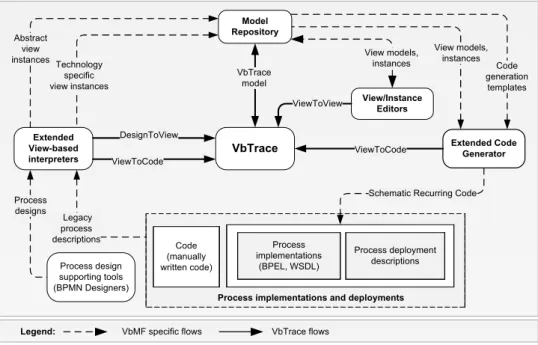
View-based, model-driven traceability framework architecture
The view-based, model-driven traceability framework architecture shown in Figure7extends the components of VbMF (see Figure4) in order to acquire traceability relationships. For instance, the extended View/Instance Editors
produces trace links between view models, between view models and elements, as well as between elements of different view models. These relationships, as mentioned above, are intrinsic parts of VbMF views, and therefore, are straightforwardly extracted. In addition, the extendedView Interpreterscan be utilized for collecting trace dependen-cies between process designs and view models, and between view models extracted from process implementations and the corresponding implementations. Last but not least, the extendedCode Generatorcan establish trace links from view models used for generating executable process code to the resulting source code artifacts. These extended components retrieve the aforementioned trace dependencies and deliver them to theVbTraceas instances of the
Model Repository Extended Code Generator View models, instances Extended View-based interpreters Process implementations (BPEL, WSDL) Process deployment descriptions VbTrace DesignToView Technology specific view instances Code generation templates
Process implementations and deployments
Code (manually written code)
Schematic Recurring Code
Legacy process descriptions ViewToCode Process designs Process design supporting tools (BPMN Designers) Abstract view instances ViewToCode View/Instance Editors View models, instances ViewToView
VbMF specific flows VbTrace flows
Legend:
VbTrace model
Figure 7: View-based, model-driven traceability framework architecture
traceability meta-model. The traceability meta-model and its instances are models themselves, and therefore, can be persisted in the model repository of VbMF for later use and maintenance. The model repository is one of our ongoing works, but beyond the scope of this article.
3.4
View-based modeling and traceability tool-chain
Process design Abstract views
Code Generator Process implementation Deployment configuration Transformation templates Technology-specific views
Figure 8: View-based modeling and traceability tool-chain
The traceability meta-model and components mentioned above are essential parts forming the view-based modeling and traceability tool-chain shown in Figure8. In this tool-chain, process design are mapped into VbMF abstract views whilst process implementations are aligned with VbMF technology-specific views by extending the view-based reverse engineering approach presented in [52,54]. During these mappings, the extended view-based interpreters are able to establish the relevant trace dependenciesDesignToViewsandViewToCodes, respectively, as well as the fine-grain relationships that areDesignViewPairsandViewCodePairs.
Nonetheless, theViewToCodesandViewCodePairscan also be derived in the course of the generation of process implementations (e.g., BPEL and WSDL code) and deployment configurations (e.g., process descriptors for deploying and executing processes in the ActiveBPEL, an open source BPEL engine [1]), from VbMF technology-specific views. The transformation templates specify the rules for generation code from VbMF models. We extend these templates to generate the relevant trace dependencies between the view models, view elements, and the generated code artifacts and code fragments.
In the following sections, we elaborate on extending the view-based interpreters and code generation templates using some scenarios in which trace dependencies are established by using our extended code generators and extended view-based interpreters.
3.4.1 Establishing trace dependencies using extended view-based interpreters
b) Trace dependencies produced from the extended FlowView interpreter
a) Extended FlowView interpreter for extracting FlowView from BPEL code and establishing corresponding trace links
Figure 9: Illustration of extracting VbMF views from BPEL code and establishing the relevant trace dependencies The view-based reverse engineering approach [54] can be utilized for extracting VbMF views from existing process implementations in BPEL and WSDL. We extend this approach such that the relevant trace dependencies are also established during the course of the reverse engineering process. Figure11(a) presents an excerpt of the FlowView interpreter in Java code that can extractAtomaticTasksof the FlowView from BPEL code. In addition, we instrument additional Java code for creating trace dependencies between the BPEL code fragment and the resulting
AtomicTasks. The generated trace dependencies are parts of theTraceability modelshown in Figure9(b). This approach can also be applied for the other view-based interpreters such as the CollaborationView, InformationView, BpelCollaborationView, and BpelInformationView interpreters [54] in order to automatically establish the relevant trace dependencies between BPEL and WSDL descriptions and VbMF views. For better supporting stakeholders in reasoning and analyzing the resulting trace dependencies, for instance, change impact analysis,Generateand
Formalizeare automatically annotated to each trace dependency.
Although the view-based reverse engineering approach presented in [54] is exemplified using process implementation languages such as BPEL and WSDL, it is extensible and applicable for mapping the concepts of a process design
b) Trace dependencies produced from the mapping of BPMN elements onto VbMF views
a) Extended template rules for mapping a DataObject(BPMN) to a
BusinessObject (InformationView) and establishing corresponding trace links
Figure 10: Illustration of mapping BPMN designs to VbMF abstract views and establishing relevant trace dependen-cies
into VbMF abstract views. Let us recall that VbMF view models at the abstract layer are intentionally designed for business experts. As a result, the concepts embodied in these view models have a close relationship to the elements of languages used for designing processes, such as BPMN, UML Activity Diagram, EPCs, and so on. A minor difference of these high-level view interpreters to the view interpreters mentioned above is that we realize the view-based reverse engineering approach using openArchitectureWare Xpand and Xtend languages [43] due to their sufficient transformation mechanisms. Figure10(a) shows an excerpt of the template-based transformation rules written in XPand language that maps a BPMNData Objectinto aBusiness Objectelement of the InformationView. In addition, the transformation rules also generate relevant trace dependencies between the design and view elements. We illustrate in Figure10(b) a part of the traceability model comprising twoDesignToViewtrace links between the design and the FlowView of the CRM Fulfillment process from the case study presented in Section4. These trace dependencies are augmented with theFormalizeof typeTraceRationale.
3.4.2 Establishing trace dependencies using extended code generators
Code generation (or so-calledmodel-to-codetransformation) is an important step of any realization of the MDD paradigm to gain productivity and ensure better software quality [51]. The results of code generation process are often the schematic, recurring code that shapes the skeleton of the software or systems. Some manually written code (aka individual code) might augment the generated schematic code in order to realize the individual parts of the business logic [51]. VbMF provides a template-based code generation approach that is able to generate schematic implementations of processes in terms of BPEL and WSDL descriptions. This approach has been realized in VbMF using the openArchitectureWare Xpand and Xtend languages [43]. We extend the template-based code generation rules in VbMF such that the trace dependencies between the involved views, view elements, and generated code
b) Trace dependencies produced from code generation
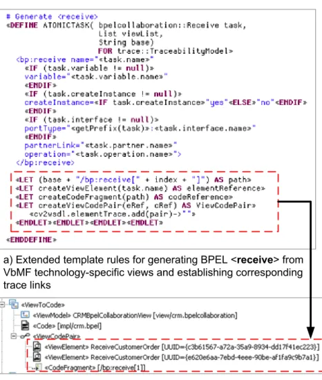
a) Extended template rules for generating BPEL <receive> from VbMF technology-specific views and establishing corresponding trace links
Figure 11: Generating BPEL code from VbMF technology-specific views and establishing relevant trace dependencies fragments are automatically established. Figure11(a) presents an excerpt of the VbMF code generation rules for generating BPEL<invoke>elements from VbMF technology-specific views along with our instrumented rules for generating trace dependencies. The resulting trace dependencies are illustrated in Figure11(b) containing a
ViewToCodetrace link between the VbMF BpelCollaborationView and BPEL<invoke>fragment extracted from the case study (see Section4). Although these trace dependencies are generated in the opposite direction to those extracted from the reverse engineering of process implementations, they share similar semantics and rationales of the trace relations that areGenerateandFormalize.
4
Tool support and case study
In this section, we illustrate the realization of the aforementioned concepts in VbTrace via the CRM Fulfillment process adapted from an industrial case study concerning customer care, billing and provisioning systems of an Austrian Internet Service Provider (cf. [11] for more details). The process is designed using BPMN and implemented using process-driven SOA technology: BPEL and WSDL. BPMN, BPEL, and WSDL are used for exemplification because these are likely the most popular process and service description languages, which are widely adopted in research and industry today. Nevertheless, our approach is not limited to those but is generally applicable for
other process-driven SOA technologies. To illustrate the process deployment configurations, we exemplify a specific BPEL engine, namely, ActiveBPEL, and develop the necessary configurations for the deployment, enactment and monitoring of the CRM Fulfillment process.
In the subsequent sections, we first quickly introduce the tool support for our traceability approach. Next, we present in detail the case study and important steps of establishing and maintaining appropriate traceability meta-data between process designs and VbMF, among VbMF views, and between VbMF views and process implementations. At the end of this section, we introduce a sample of using traceability path derived from the traceability model for better understanding and analyzing the relationships of process development artifacts.
4.1
View-based, model-driven integrated development environment
A proof-of-concept of view-based, model-driven approach has been implemented in [52–54] using the Eclipse Modeling Framework (EMF) [9] and openArchitectureWare MDD Framework [43]. In this article we have realized the concepts of our view-based, model-driven traceability approach presented based on the aforementioned VbMF implementation and integrated them with VbMF in terms of an view-based, model-driven integrated development environment. In order to effectively reuse and extend VbMF concepts and mechanisms, the traceability framework is derived from the EMF Ecore meta-model. The biggest advantage of using Eclipse Modeling Framework is that we gain better interoperability with the Eclipse BPMN Modeler [19] which is developed based on EMF Ecore. For the sake of demonstration, we use the BPMN diagrams designed in the Eclipse BPMN Modeler to represent the process design, and extend the tree-based editor generated by EMF for presenting and manipulatingTraceability modelsfrom now on. The components of our traceability framework, such asExtended Code GeneratorsandExtended View-based Interpreters(see Figure7), are derived from corresponding VbMF components (see Figure4) using the mechanisms described in Section3.4.
4.2
CRM Fulfillment process
The CRM Fulfillment process is a part of the customer relationship management (CRM), billing, and provisioning systems of an Austrian Internet Service Provider [11]. The main business functionality of the CRM Fulfillment process is to handle a customer order of the company’s bundle of Internet and telecom services including a network subscriber line (e.g., xDSL), email addresses, Web-based administration (VMX), directory number, fax number, and SIP URL for VoIP communications. The process uses a wide variety of in-house services and services provided by various partners. The company has developed and deployed in-house services for customer relationship information management, assigning fax numbers, SIP URLs, and mail boxes, initializing VMX, and sending postal invoices to customers.
The process uses a credit bureau service provided by a third party business partner of the financial institution that acquires, stores, and protects credit information of individual and companies. The credit bureau service can verify a customer’s payment account for accuracy and validity and charge the payment according to the customer’s purchase order. Customer premise equipment (CPE) partners supply services for ordering and shipping home modems or routers. Telecom partners offer services for checking, assigning, and migrating customer directory numbers (DN). These services expose their functionalities in terms of WSDL interfaces that can be orchestrated using BPEL processes.
Figure12shows the design of the CRM Fulfillment process in terms of a BPMN diagram in Eclipse BPMN Modeler. The process is initiated as a customer places a purchase order. Then, the customer relationship management service is invoked to update the customer’s profile. Next, the process invokes a bank service to validate the customer’s account
1 2
3 4
Figure 12: The development of CRM Fulfillment process in view-based, model-driven integrated environment: (1) The process design in BPMN Modeler (2) VbMF views, (3) Traceability view, and (4) Generated process implementation validity. In case a negative confirmation is issued from the bank service, e.g., because the account number is invalid or the owner and account do not match, the order will be canceled. Otherwise, the positive confirmation will trigger the second branch in which the process continues with a number of concurrent activities to fulfill customer order’s requests and deliver networking equipments, e.g., home modems or routers, to the customer’s shipping address. For the sake of simplicity, we assume that those activities finish without errors. After all of these activities finished, the customer’s payment account is charged and a postal invoice will be sent to customer’s billing address.
4.3
CRM Fulfillment process development and traceability
Figure12depicts one of development perspective of the CRM Fulfillment process using our view-based, model-driven integrated environment, which is an Eclipse-based workbench. The stakeholders can create and manipulate process views in the various VbMF view editors or extract views from process designs and implementations using the built-in view-based reverse engineering. Given these process views, stakeholders can generate process implementations such as process code in BPEL, service interfaces of processes in WSDL and process deployment configurations by using the predefined template-based code generation rules. Moreover, the code generation templates can also be customized according to further needs by using the the XPand language editor [43]. In addition, the trace dependencies established during the course of process development are presented to the stakeholders in the Traceability view. The subsequent sections present the various scenarios to demonstrate how relevant trace dependencies between process designs and VbMF views, between VbMF views, and between VbMF views and process implementations
are established during the course of modeling and developing the CRM Fulfillment process. 4.3.1 Scenario 1: Traceability between process design and VbMF views
Update CustomerProfile Verify BankAccount Create Mailbox Assign SIP Migrate DN Initialize VMX ShipCPE Check DN Assign DN Send Invoice Receive Customer Order Reply Order Confirmation Cancel CustomerOrder Assign Fax Charge Customer Account
a) CRM Fulfillment process design b) CRM Traceability model c) The CRM Fulfillment FlowView
Figure 13: Illustration of mapping CRM Fulfillment process design (left) onto VbMF FlowView (right), and establish-ing trace dependencies (middle)
The CRM Fulfillment process design is a BPMN diagram that comprises a number of notational elements such as a pool, tasks, data objects, and sequential flow connectors (see Figure12). For the sake of readability and demonstration, we adapt the design of CRM Fulfillment process and omit theData Objects which are irrelevant in this scenario. In the context of process-driven SOAs, VbMF leverages the FlowView model as the central notation because this model represents the orchestration of the process activities [52,53]. We demonstrate the mapping of the BPMN design onto the FlowView of the CRM Fulfillment process along with the trace dependencies established during the mapping (see Figure13) by using the approach mentioned in Section3.4. The trace dependencies includes trace links at coarse-grained levels, i.e., between the BPMN diagram and the FlowView model, or at finer granularities, e.g., between a BPMN task and a FlowView’sAtomic Task, between a BPMNGatewayDataBasedExclusiveand a conditional switch, namely,Exclusiveof the FlowView, and so on. Taking the same approach of mapping the CRM Fulfillment process design onto the FlowView, we have developed more view-based interpreters for extracting abstract view models from the process design and establishing tracing relationships.
Note that VbMF is a realization of theseparation of concernsprinciple [52,53]. In VbMF, the FlowView model merely represents the control structures, i.e., the orchestration concern of business processes that describe the execution order of process activities in order to accomplish a certain business goal. However, the FlowView does not contain any details of these tasks. Other views, according to their specific syntaxes and semantics, provide the concrete definitions of each of FlowView’s tasks. For instance, a service invocation task of the FlowView is realized in a CollaborationView or an extension of the CollaborationView whilst a data processing task is defined in an InformationView or an extension of the InformationView. In this way, the FlowView model aims at supporting stakeholders, especially business experts, to quickly design the business functionality by orchestrating named activities rather than being stuck with other details such as performing remote invocations, activity compensation, and so on. These details are accordingly defined in abstract view models and/or refined down to technology-specific view models by the
relevant IT experts. As a consequence, these views, regardless whether they are abstract or technology-specific, can be integrated with the FlowView using the view integration mechanism [52,53] in order to produce richer views or a thorough view of the whole process with respect to the particular needs, knowledge, and skills of stakeholders.
a) CRM Fulfillment CollaborationView b) CRM Traceability model c) The CRM Fulfillment BpelCollaborationView Figure 14: Illustration of establishing traceability (middle) of model refinements from the CRM CollaborationView (left) to the BpelCollaborationView (right)
4.3.2 Scenario 2: Traceability between VbMF views
View models at the abstract layer of VbMF are intentionally designed for business experts alike who are not familiar or able to work with the technical details. As such, these models supplement the FlowView with adequate concepts and perspectives. In other words, the abstract views can be considered platform-independent models (PIMs) [12,51] that have close relationships with process designs rather than the implementation counterparts. In the model-driven stack of VbMF, an abstract view can be gradually refined down to its corresponding technology-specific view. For instance, the BpelCollaborationView is a stepwise refinement of the more abstract CollaborationView (cf. [52,53]). Thus, refinement relationships are important for tracing from process design to implementations. We track these relationships by using trace links of the typeViewToViewfor supporting the traceability between two view models, and a number ofViewElementPairseach of which holds references to the corresponding view elements.
Figure14shows an illustration of establishing the trace dependencies out of the refinement of the CRM Collabora-tionView (Figure14(a)) down to the CRM BpelCollaborationView (Figure14(c)) described by theViewToViewand its constituentViewElementPairs. For the sake of readability, we only present a number of selected trace dependencies and use the arrows to depict the links described by each dependency. Each trace dependency is augmented with the
Refineof typeTraceRationale.
Additionally, VbMF views can be integrated to produce richer views. For instance, a certain stakeholder might need to see the orchestration of the CRM Fulfillment process activities along with the interactions between the process and other processes or services. The combination of the FlowView model and either the CollaborationView or the BpelCollaborationView based on the name-based matching approach described in [52,53] can offer such a perspective. Figure15shows an illustration of establishing the trace relationships out of such combinations. The
a) CRM Fulfillment FlowView b) CRM Traceability model c) The CRM Fulfillment BpelCollaborationView
Figure 15: Illustration of establishing trace dependencies (middle) of an integration of CRM FlowView (left) and BpelCollaborationView (right)
main purpose of view integration is to enhance the flexibility of VbMF for providing various adapted and tailored perspectives of the process model. Because those perspectives might be used by the stakeholders for analyzing and manipulating the process model, we track down the relationships caused by the above-mentioned combination in the traceability according to specific stakeholders’ actions and augment them with theDependencytype.
4.3.3 Scenario 3: Traceability between VbMF views and process implementations
1
2
3
Figure 16: Illustration of establishing traceability (3) between VbMF views (1) and process implementations (2) In the previous sections, we illustrate the methods for establishing the traceability path connecting the CRM Fulfillment process design to VbMF view models at the abstract layer down to the technology-specific layer. The relationships between view models and process implementations, however, can be achieved in two different ways.
1
2
3
Figure 17: Illustration of establishing traceability (3) between VbMF views (1) and process deployment descriptors (2) On the one hand, schematic code of process implementations or process deployment descriptors can be generated from the technology-specific views (such as the BpelCollaborationView, BpelInformationView, etc.) at the final step of VbMF forward engineering tool-chain [52,53]. On the other hand, the reverse engineering can also automatically extract view models from existing (legacy) process implementations [54]. Regardless of using any of these methods, the trace dependencies need to be recorded to maintain appropriate relationships between view models and process implementations to fully accomplish the traceability path from process designs to the implementation counterparts (see Figure16)2.
Furthermore, a number of process engine specific descriptors are necessary for successfully deploying and executing the CRM Fulfillment process. In this article, ActiveBPEL is exemplified as the reference process engine to deploy and execute the CRM Fulfillment process in this article. Utilizing the extended code generators mentioned in Section3.4, VbMF can generate the process deployment descriptors and establish the trace links. Figure17depicts the trace dependencies created during the course of generating process deployment descriptor required by the ActiveBPEL engine from VbMF views.
4.4
Leveraging VbTrace – A sample traceability path
Establishing trace dependencies alone is not sufficient for tasks like change impact analysis, change propagation, artifact understanding, and so on, it is the important factor for supporting any such tasks [49]. In this section, we examine a sample traceability path based on the traceability model created in the previous sections to illustrate
2For the sake of readability, we omitted irrelevant elements and namespace bindings in the BPEL and WSDL code and process deployment
Receive Customer Order CRM Fulfillment Diagram CRM CollaborationView CRM BpelCollaboration View «Code» crm.bpel «Interaction» ReceiveCustomerOrder «receive» ReceiveCustomerOrder CRM FlowView «AtomicTask» ReceiveCustomerOrder
1
2
3
Legend Artifact traces Element tracesFigure 18: Illustration of a traceability path from the CRM Fulfillment process design (1) through VbMF views (2) to process implementations (3)
how our traceability approach can support these tasks. Figure18depicts a simple traceability path from the CRM Fulfillment process design through the VbMF framework to the process implementations. The traceability path comprises the trace dependencies between the process design and VbMF views mentioned in Section4.3.1followed by the relationships among VbMF views retrieved in Section4.3.2. The process implementation is reached at the end of the traceability path by using the trace dependencies between VbMF technology-specific views and process code described in Section4.3.3.
Let us assume that there is a business expert working on the BPMN Modeler in order to analyze the CRM Fulfillment process functionality and change the process design. These changes must be accordingly reflected in the process implementations in BPEL and WSDL and even in process deployment configuration. Without our traceability approach, the IT experts have to look into the BPMN diagram and manipulate BPEL, WSDL code and process descriptors manually. This is time consuming, error-prone and complex because there is no explicit links between these languages. In addition, the stakeholders have to go across numerous dependencies between various tangled concerns, some of which might be not relevant to the stakeholders expertise (cf. the statistics in Figure2). Using our approach, the business experts can analyze and manipulate business processes by using either the process designer or the VbMF abstract views such as the FlowView, CollaborationView, InformationView, and so on, depending on their needs and knowledge. The IT experts, who mostly work on either technology-specific views or process code, can better analyze and assess coarse-grained or fine-grained implications of these changes based on the traceability path connecting the process design and implementation at different levels of granularity.
5
Related work
Being extensively studied in literature and industry, dependency relationships between designs and implemen-tations are often used for tracing through development artifacts, supporting change impact analysis, artifacts understanding, and other tasks [49]. Spanoudakis and Zisman [49] presented a summary of the state-of-the-art traceability approaches that focus on the tracing between stakeholders and requirements [14], between requirements [4,14,22,45,47,55,61], between requirements and designs [8,10,21,22,46,47], between designs presented in [10,47,55,60], between requirements and code [5,10,28,47], and between code artifacts [47]. There are only a few
approaches for supporting traceability between designs (e.g., UML Class diagrams) and code [8,10,22,28,47]. Each of the aforementioned design-to-code traceability approaches, however, merely focus on specific types of dependen-cies, for instance,overlap relations[10],evolution relations[8,28,47], andgeneralization/refinement relations[22]. These approaches do not mention the extensibility to other types of dependencies or the ability to cover different levels of granularity of trace dependencies.
The difference of abstraction and granularity and the diversity of language syntaxes and semantics hinder the automation of establishing and maintaining the traceability between high-level artifacts, such as requirements or design specifications, and very low-level artifacts, such as executable code. There are few promising efforts on supporting automatic generation of trace dependencies that use information retrieval techniques [5,6,15,24,25,29] or rule-based traceability [26,46,50]. To the best of our knowledge, the traceability retrieved from the aforementioned approaches does not cover the difference of granularity at multiple levels of abstraction, which is the first challenge we described in Section1. In addition, [23,47] suggested that a traceability approach only supports the representation of different trace dependencies between artifacts, but the interpretation, analysis, and understanding of the relationships extremely depend on the stakeholders. According to his specific needs, knowledge, and experience, a stakeholder might be interested in different types of dependencies of different levels of abstraction. Most of traceability approaches described above, except [14], have not provided adequate support for different stakeholder interests.
Recently, model-driven development (MDD) [12,51], which gradually gains widespread adoption in both industry and research, provides an efficient paradigm to potentially reconcile the difference of granularity at various levels of ab-straction by introducing a number of intermediate (semi)-formal modeling layers, such as the platform-independent models (PIMs) and platform-specific models (PSMs) [12,37]. Each modeling layers can provide different abstractions of systems and software which are tailored to specific stakeholders’ knowledge and experience. Moreover, model transformations provide better facilities for the automation of creating and maintaining traceability relationships [2,13]. A number of research approaches have exploited these advantages for establishing and maintaining traceability between development artifacts [3,7,27,34,36,58], to name but a few, in order to support reducing the gap between design and implementation.
The lightweight traceability approach TRACES proposed in [3] can support tracing requirements across different models and levels of abstraction. Based on the assumption that each artifact has a unique identifier, and code is fully generated from the models ( which is hard to achieve in reality [51]) TRACES offers mechanisms for eliciting traceability links from requirements to models, i.e., PIM and PSM, and from the models to code. Mäder et al. [27] analyze and classify Unified Process (UP) artifacts to establish a traceability link model that helps in (semi)-automatically establishing and verifying traceability links in Unified Process development projects along with a set of rules for management of the links. Leveraging model transformations, Naslavsky et al. [34] propose an approach for creating fine-grained traceability among model-based testing artifacts in order to support result evaluation, coverage analysis, and regression testing. Oldevik and Neple [36] present an approach for handling text-based traceability links in model-to-code transformations (aka code generations) which is a key contribution to OMG MOF Model to Text Transformation standardization effort [38]. This approach provides a meta-model including a set of concepts for traceability between model elements and locations in code artifacts. The corresponding part of our traceability meta-model, i.e., the trace dependencies between views and code artifacts, is inspired by [36]. Walderhaug et al. [58] present a generic approach for traceability in MDD aiming to enhance sharing and integrating of traceability information from different development tools. The authors propose a high-level representation of the traceability process in the course of software development that provides general concepts for representing different kinds of stakeholders and artifacts used for traceability, such as trace model, trace repository, and the interactions between
the stakeholders and these artifacts. Bondé et al. [7] propose an approach that offers a traceability meta-model for representing the relations between artifacts and the transformation operations associated with these relations. Once the traceability is accomplished, it then can be used to enforce the interoperability of models at different levels of abstraction, for instance, between a PIM and PSM.
Our work has the commonalities with the MDD-based traceability approaches in using traceability meta-models for (semi-)formalizing trace dependencies in order to enhance the interoperability of tools. In contrast to the related work, we introduce the combination of theseparation of concerns principlesrealized by the notion of views and the
separation of abstraction levelsrealized by the MDD paradigm as a better solution for supporting traceability in process-driven SOAs. We exploit the notion of views to efficiently represent different process concerns such that stakeholders are provided with tailored perspectives by view integration mechanisms according to their specific needs, knowledge, and experience. This is a significant step toward the support of adapting process representations and trace dependencies to particular stakeholder interests. In addition, theseparation of abstraction levelsoffers appropriate intermediate layers to gradually bring the business experts working at high levels of abstraction close to the IT experts working at lower levels of abstraction. Using the separation of process concerns in terms of (semi-)formalized views and the view integration mechanism, the refinement between two adjacent abstraction levels can be alleviated in a better and more flexible manner. Obviously, the relationships between our modeling artifacts such as views and view elements are intrinsic and can be retrieved straightforwardly from the view models. Leveraging these modeling concepts and mechanisms, we perform the mapping of process designs (here: BPMN) onto high-level, abstract views and process implementations (here: BPEL and WSDL) onto low-level, technology-specific views and devise a traceability meta-model that is rich enough to represent the trace dependencies from design to implementation through different abstraction levels and different granularity. Furthermore, our framework is quite open for extensibility, such as adding more traceability relationships at finer granularity with adequate specializations of theArtifactTraceand theElementTrace, adding more intermediate view model layer, or adding more appropriate specializations of theTraceRationalemeta-class to support enhancing traceability reasoning or change impact analysis.
In the area of process-driven development, there are a number of approaches that define transformations between different languages [31–33,44,48,59]. These approaches partially provide the link between process design and implementation. However, most of these approaches focus on only one process concern, namely, the orchestration concern, and ignore other significant ones, such as collaborations, data processing, fault handling, and so on. As a consequence, each of these approaches is applicable for transforming of control structures of two specific kinds of languages, for instance, BPMN and BPEL [44,48], EPC and BPEL [33,59], and so forth. As a consequence, these approaches offer neither the extensibility to support the various process concerns, except the control flow, nor the traceability of these concerns of processes. Nonetheless, our traceability approach benefits from different algorithms described originally in those approaches for mapping the control flow of process design onto our FlowView model (cf. Scenario 1).
Table1and2present qualitative comparisons of our view-based, model-driven traceability approach, VbTrace, and a number of selected related approaches which are most closely related to VbTrace, such as theMDD-basedtraceability approaches that utilize model-driven paradigm with modeling layers ranging from high-level into low-level and/or exploit model transformations for traceability between design and implementation [3,27,36,58]. The comparison criteria are adapted from [49].
Support for multiple trace re-lations
Generation of trace relations Relation representation Support adaptation of stakeholder in-terests
TRACES by Alesky et al. [3]
[3] offers the Reference or
Realize relations between requirements and models and the Generate relations between models and code. Re-alizerelations can be inferred from above relations.
Creation of explicit trace-ability links between require-ments and models is the responsibility of the modeler. Traceability links can also be automatically retrieved from code generation.
[3] does not explicitly present a formalization of trace depen-dencies.
Not supported yet
UP traceability by
Mäder et al. [27]
[27] focuses on four trace re-lations:Refine,Realize,Verify, andDefine.
Trace dependencies are estab-lished with adequate interven-tions of stakeholders of UP.
Existing UML notational ele-ments are used for represent-ing trace dependencies. Trace dependencies are stored in the source code as annotations.
Not supported yet
Model-based test-ingby Naslavsky et
al. [34]
[34] the trace relations be-tween models and test arti-facts.
The generation of test cases and relevant traceability model is currently manual.
The traceability model de-scribes the relationships achieved in a typical model transformation and is per-sisted as an Ecore model.
Not supported yet
M2Tby Oldevik et al. [36]
[36] focuses on the trace relations between models, i.e., PSMs, and text gener-ated from the models, i.e.,
Generaterelations.
Trace dependencies are au-tomatically generated from model-to-code transforma-tions.
[36] defines a meta-model pro-viding a set of concepts for traceability between model el-ements and locations in code artifacts.
Not supported yet
Generic MDD traceability by Walderhaug et al. [58]
As [58] presents a high level and generic solution to trace-ability for MDD, no concrete trace dependencies are con-sidered. Thus, further ef-forts are required to specialize and adapt the traceability and repository models to particu-lar needs.
[58] merely refers to other traceability approaches for achieving trace dependencies such as [36].
A number of high level meta-model are defined to represent general concepts of traceabil-ity, such as trace model, arti-fact type, trace type, etc. as well as the stakeholders inter-actions.
[58] offers a number of pre-defined stakeholders roles, such as developer, trace user, traceability manager, and tool supplier, who involve in the MDD paradigm but does not provide mech-anisms to support the adaptation of trace dependencies to the various stake-holders interests.
VbTrace Support multiple relation
types by the annotation of adequate TraceRationales(cf. Section3.2).
Trace dependencies between process design and views, between views and code are accomplished (semi-)automatically, between views and view elements are re-trieved straightforwardly (cf. Section4.3).
(Semi-)formalized representa-tion in terms of a rich, exten-sible traceability meta-model aiming at supporting inter-operability and sharing of trace dependencies (cf. Sec-tion3.2).
The combination of separation of con-cerns and separation of abstraction lev-els is a significant step toward support the adaptation of process representa-tions and trace dependencies to vari-ous stakeholder interests. Moreover, theRolemeta-class, a specialization of
TraceRationale, can be annotated to the trace links to better support adaptation and reasoning of trace dependencies and traceability path with respect to particular stakeholders.
Table 1: The comparison of related work
Support intermediate model-ing layers
Support for multiple granu-larities
Extensibility options Tool support
TRACES by Alesky et al. [3]
[3] supports traceability be-tween requirement and model elements and between model elements and code but does not mention any support for inter-mediate modeling layers (i.e., model and code merely have an equivalent abstraction).
Not supported Not supported A prototypical development envi-ronment which can be integrated with Eclipse and CodeBeamer for development and traceability. Models are stored in either XML or XMI formats.
UP traceability by Mäder et al. [27]
[27] focuses on traceability be-tween four abstraction levels of UP: requirement, analysis, de-sign, and implementation mod-els.
[27] aims to support the trace-ability between basic UML ar-tifacts of UP abstraction lev-els.
[27] is merely bound to UP/UML. Not supported yet
![Figure 3: Overview of the View-based Modeling Framework ([17, 52, 53])](https://thumb-us.123doks.com/thumbv2/123dok_us/9498486.2432391/4.892.154.705.369.698/figure-overview-view-based-modeling-framework.webp)
![Figure 9: Illustration of extracting VbMF views from BPEL code and establishing the relevant trace dependencies The view-based reverse engineering approach [54] can be utilized for extracting VbMF views from existing process implementations in BPEL and WSD](https://thumb-us.123doks.com/thumbv2/123dok_us/9498486.2432391/12.892.198.685.356.756/illustration-extracting-establishing-relevant-dependencies-engineering-extracting-implementations.webp)