Image-Based Model Acquisition and Interactive
Rendering for Building 3D Digital Archives
Ying-Chieh Chen1, Chun-Fa Chang1, Zong-Nan Shen1, Yong-Min Chen1,Hong-Long Chou2
1Department of Computer Sciences, National Tsing Hua University 2Opto-Electronics and Systems Laboratories, Industry Technology Research Institute
Abstract. We demonstrate a process and a system for building three-dimensional (3D) digital archives of museum artifacts. Our system allows the targeted audience to observe the digitized 3D objects from any angle and at any distance, while still conveys the textures and the material properties with high fidelity. Our system acquires input images mainly with a handheld digital camera. Therefore it is portable and easy to set up at the museum sites. The results we show include two digitized art pieces from the Yingko Ceramics Museum at Taipei County, Taiwan. Our system can also use a QuickTimeVR object movie as the initial input, which we demonstrate using the Jadeite Cabbage data from the National Palace Museum.
1 Introduction
Just like two-dimensional (2D) photographs can deliver richer information than words and texts, there is a lot more information that can be conveyed in three-dimensional (3D) form. A good example is the 3D visualization of CT or ultrasound scans in the medical community. Therefore, building 3D digital archives for important museum collection and art pieces will certainly allow those contents to reach the audience more vividly. During the early stage of our study, we visited the Yingko Ceramics Museum at Taipei County, Taiwan. One of the most important archives in the Yingko Ceramics Museum that many scholars would like to access for further research is its collection of historic Koji ceramics (交趾陶). However, the historic Koji ceramics are so fragile that those scholars often have access to their photographs only. With 3D digital archives, those scholars would have more freedom and closer views of the Koji ceramics without the risk of damaging them.
Therefore, the goal of our work is to develop advanced techniques for creating 3D digital archives of museum art pieces. The 3D geometric and surface material models that we obtain must allow the viewers to look at the digitized 3D objects from any angle and at any distance, while still convey the textures and the material properties of the 3D objects with high fidelity. In addition, we want our system to be portable and easy to set up, so we can bring it to the museum sites for the scanning of the artifacts (instead of the other way around).
Many different methods exist for creating three-dimensional models in computer graphics. In the gaming and animation industry, 3D models are mostly created
manually by 3D artists using 3D modeling programs. However, the manual 3D modeling process is time consuming. It is also difficult to produce precise 3D models that are required for digital archives. Using automatic 3D scanning is an alternative to the manual 3D modeling process. Many of the 3D scanning methods have limitations on the types of object materials, which we discuss in Section 2. In this work, we use an image-based method that has fewer limitations on the material types. Our system acquires input images mainly with a handheld digital camera. Therefore it is portable and easy to set up at the museum sites. The results we show include two digitized art pieces from the Yingko Ceramics Museum at Taipei County, Taiwan. Our system can also use a QuickTimeVR object movie as the initial input, which we demonstrate using the Jadeite Cabbage data from the National Palace Museum.
2 Related Work
There are many works about how to construct 3D models, and how to show these models realistically in real-time. One way to get a highly accurate 3D model is to use the laser range scanners such as [1], but they usually do not work well on objects with dark or glossy surfaces, and translucent objects such as the Jadeite Cabbage data from the National Palace Museum. The structured-light based systems such as [2] have a different problem from the laser scanners: they do not work well on highly textured surfaces because the textures could interfere with the structured light. There are also lots of methods proposed to reconstruct 3D models in computer vision. Most of them require many correspondent points, but getting a dense set of correct correspondences is a hard problem. They also face problems that are caused by glossy materials because the colors and the highlight on glossy surfaces could change rapidly according to the camera position.
In this work, we use an image-based method which uses digital photographs as the input. There are many other image-based modeling and rendering methods, such as the image-based visual hulls (IBVH) [11] and the Light Field Mapping [6]. Like our method, image-based visual hulls and the opacity hulls [12] construct the 3D shapes from the silhouettes. Our system uses handheld cameras instead of a well-calibrated gantry, thus is more portable and easier to set up than the opacity hulls. Unlike Light Field Mapping, our system does not assume the existence of a precise 3D geometric modelof the scanned object. The QuickTime VR system [5] is similar to our system in two aspects: it does not require a precise 3D geometric model and it needs lots of photographs taken around the scanned object. However, it renders the models by choosing or blending a few original input images, thus limiting the viewing distance and angle. In this work, we show that a QuickTime VR object movie can also be used as the input to our system.
3 Our
System
In this project, we develop a process to reconstruct 3D models and render them. In conventional 3D scanning techniques, it is hard to reconstruct the object with glossy materials, translucent materials, and dark surfaces. But our process can reconstruct the object of almost any material. We can display the object at any viewing angle and distance. Besides, we also capture the specular reflection which changes with the view.
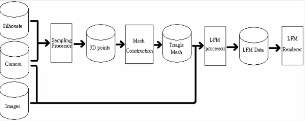
The workflow is shown in Figure 1. In this process, we use lots of photographs to reconstruct the 3D model and render the object in real time. The photographs, their silhouettes, and the camera information are the inputs to our system. In practice, the silhouettes may be extracted from the photographs by image processing and the camera information may be recovered by computer vision techniques. Therefore, the most important inputs are the photographs. In previous works involving visual hulls [11][12], the cameras are mounted on a pre-calibrated gantry to avoid the difficult tasks of recovering the camera information from photographs. A lesson we learned during this project is that the quality and accuracy of the resulting visual hulls are very sensitive to the errors in the recovered camera information. The detail of camera calibration is described in Section 3.1.
After we get the camera information and silhouettes, we can obtain the 3D points on the surfaces of the desired object by our sampling method. We use the concept of shape-from-silhouette to construct the visual hull of the object. After constructing the hull, we obtain many 3D samples on the surfaces of the hull (Section 3.2.1). After we get those 3D points, we use them to reconstruct a triangle mesh. This is discussed in Section 3.2.2.
We use the Light Field Mapping (LFM) [6] technique for rendering. What LFM needs is a 3D mesh and calibrated photographs. There are two stages in LFM, namely the LFM processor and the LFM renderer. The LFM processor is a preprocess that transforms the original data to LFM data. And the LFM renderer can use this LFM data efficiently for view-dependent texture mapping. The detail is further described in Section 3.3.
3.1 Data Acquisition and Calibration
There are two ways to get the input photographs: we could take new photographs using hand-held cameras or we could use existing photographs. The later could happen if the object to be scanned no longer exists. It also applies to the cases where many photographs are already taken for other purposes, such as for building a QuickTime VR (QTVR) object movie.
To recover the camera information (i.e., the intrinsic and extrinsic parameters) from all the photographs, we may place markers around the scanned object to simplify the calibration process. We discuss this approach further in Section 3.1.1. However, it is more difficult to obtain the calibrated camera parameters from the exiting photographs since this is a classical computer vision problem. In this work, we only consider existing photographs that are associated with a QuickTime VR object movie. More detail is in Section 3.1.2.
3.1.1 Photographs from Hand-Held Cameras
A natural way to obtain images of the scanned object from various angles is to use a handheld camera, as long as we can recover the camera poses afterwards. We use the self-calibration method suggested by Zhang [16] to obtain the intrinsic camera parameters and the lens distortion parameters (Figure 11). Then we put some markers around the object to be captured in order to find the extrinsic camera parameters (Figure 12).
The markers that we place around the scanned object for calibration purpose could present problems for large objects and for glossy objects. The problem arising from large objects is that they could occlude the markers that are required for calibration. Our solution is to use sparsely placed markers instead. For objects containing highly glossy or reflective surfaces, the pattern of the markers might appear in the reflection. To eliminate the reflection, we need to take two pictures of each view, one for the calibration, and the other for the actual acquisition. The first picture is taken with the markers. The second picture is taken at the same position, but with the markers covered by papers that have similar color to the desk. A tripod is used to make sure the two pictures are taken at the same position.
3.1.2 QuickTime VR Dataset
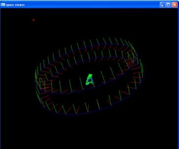
It is desirable sometimes to reconstruct 3D model from existing photographs. In this work, we choose the QuickTime VR (QTVR) data of “Jadeite Cabbage with Insects” (or just “Jadeite Cabbage” in short) for experiment. The QTVR data of Jadeite Cabbage contains 360 pictures which are taken around it. Figure 2 shows the roughly estimated camera positions in the Jadeite Cabbage dataset, where the looking direction, the up direction, and the right direction are drawn as 3 lines colored red, green and blue respectively.
QuickTime VR (QTVR) is a technique that can model and display an object by many 2D photographs. Once the viewer determines the viewing direction and distance, QTVR chooses one or several photographs with the closest viewing condition to produce the current view. Since no 3D model is actually reconstructed in the original QTVR method, the camera positions that are stored in the QTVR data do not need to be precise. However, to construct a 3D model from the QTVR data, we need to recover more precise camera information for every picture.
Figure 2: The 360 camera positions of the Jadeite Cabbage data set. The red, green and blue lines show the viewing, up and right directions of camera poses respectively.
Figure 3: The 72 camera poses that are recovered from the QuickTime VR object movie of the Jadeite Cabbage.
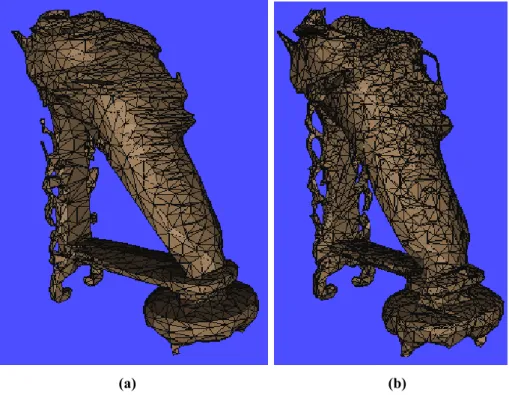
At first look, it seems easy to find the camera positions in a QTVR dataset. Usually, a QTVR object movie data is captured with a regular camera movement. For example, the Jadeite Cabbage data contains pictures taken from camera positions that form 10 circles. The camera positions within each circle are placed at about every 10 degrees (Figure 2). This leads to the assumption that the camera positions are placed regularly on a hemisphere and rotated around a fixed point (as shown in Figure 2). Unfortunately, such an assumption did not produce satisfying results, as shown in Figure 7(a).
Subsequently, we use the “structure form motion” technique in [7] to obtain the calibrated camera parameters. Note that it is time consuming to obtain precise camera parameters, because it requires manual input to establish initial image correspondences. In the case of Jadeite Cabbage, we choose 72 views to calibrate, and the results are shown in Figure 3. A point worth mentioning is that the recovered camera parameters do not point to a common center point, which explains why our previous assumption did not produce good results. Figure 7(b) shows the improved results using the calibrated camera parameters.
3.2 Model Reconstruction
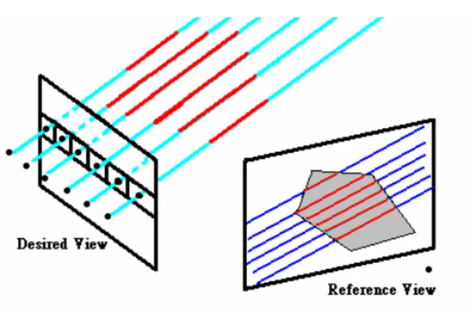
Figure 4: The concept of image-based visual hulls.
3.2.1 Sampling
After we get the camera information, we can start to reconstruct the 3D model using the silhouette images. We use the concept of shape-from-silhouette to construct the visual hull of the object. After we get the hull, we can shoot a ray from every pixel of a desired view to get all the samples on the surface of the visual hull.
In visual hull we have two kinds of view, namely the reference view and the desired view. The desired view is the view where the visual hull is sampled, and the
reference views are the input silhouette images. First, we shoot a ray (L, the cerulean blue lines in Figure 4) from every pixel of desired view and project the line (L) onto the reference view (L’, the deep blue lines in Figure 4). Second, we check and record the intersection of the lines with the silhouette on the reference image (the red part of L’ in Figure 4) and project these intersected parts back to the lines (L) to get the intersected lines in object space (the red part of L in Figure 4). We calculate the intersection with silhouette for every reference image. Finally, the endpoints of red lines in object space represent the sample points on the visual hull.
There is a problem about undersampling at the thin features of model, such as the limb of the insect that forms a loop on the Jadeite Cabbage (Figure 10). It happens especially when the surface of the object is nearly orthogonal to the desired image. Therefore, we sample the object from three directions (top, front, right directions) to form a layer-depth cube (LDC) [14] so that we have sufficient information to reconstruct the model in the next step. This could produce a lot of dense points on the surface of the model. In the case of Jadeite Cabbage, we get 25,590,758 sample points
3.2.2 Triangulation
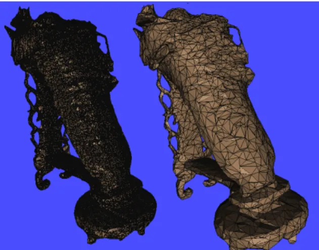
The visual hull we obtain in the previous step contains sample points on the surfaces. The next step is to construct a triangle mesh from them. There are at least two methods to build the triangle mesh: surface reconstruction and function reconstruction. The function reconstruction method is to use a function to represent the mesh, and to minimize the difference between the surface and the sample points. The surface reconstruction method is to connect the sample points directly. In this work, the function reconstruction method is not suitable. It is because our sample method has similar sample rate at every part of surface. If we apply the method of function reconstruction, a problem may occur at the thin features of the model. Those thin features do not have enough information to make the function converge, which cause a swelling at those parts. Since we have densely sampled points and we know all the sample points are on the surface of the model without significant noise, we choose the surface reconstruction method to triangulate the mesh. What we use is the “Power Crust” method in [3]. A mesh we constructed is shown in Figure 5.
3.3 Rendering
Once we obtain the 3D mesh, we may combine it with the input photographs to form the surface light fields [15] and to produce view-dependent texturing and shading effects. For the rendering, we use the Light Field Mapping (LFM) method which can render the surface light fields in real time [6].
Figure 5: Triangulated mesh.
During preprocessing, the LFM compresses the surface light field data to a compact representation. In the original LFM work, a more precise 3D mesh is constructed using a structured-light based method. Here, we use the approximating visual hulls instead.
Because the LFM uses graphics hardware to accelerate its rendering, itinevitably limits the complexity of the 3D mesh because each triangle of the mesh requires associated surface map and view map to be loaded to texture memory. Currently, a typical graphics card contains up to 256MB of video memory and supports maximum texture size of 4096 by 4096. This limits our 3D mesh to about 9000 triangles. We use polygon simplification methods such as the QSIM [13] to reduce number of triangles in the 3D mesh. Figure 6 shows an example.
4 Results
The results of three datasets, Teapot, Vase, and Jadeite Cabbage, are shown in the following. The teapot and the vase data are captured with a handheld camera. The Jadeite Cabbage is from an existing QuickTime VR object movie.
Teapot (Figure ):
The Teapot has more features in its shape which is a good test for the visual hulls. It uses a 3000-triangles mesh and 72 pictures. The size of the resulting LFM data is about 22MB. The frame rate during rendering is about 60 frames per second in the resolution of 756 x 406. Figure shows 3 novel views of the Teapot.
Vase (Figure 9):
The Vase has a simpler shape than the Teapot, but has more glossy and textured surfaces which are good tests for light field mapping. It uses a 1000-triangles mesh and 27 pictures. The LFM data size is about 10.9MB. The frame rate is about 60 frames per second in the resolution of 756 x 406.
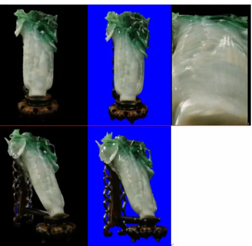
Jadeite Cabbage (Figure 10):
We use 72 pictures and a 9000-triangles mesh to render the “Jadeite Cabbage with Insects” from an existing QTVR dataset. The frame rate is about 20 frames per second in the resolution of 756 x 406. Figure 10 also compares the results with the source images.
When we use a hand-held camera to capture input images, it takes about 30 minutes to complete a set of about 30 views. We used a tripod and a cable release to avoid camera vibration, which also reduces the capture time and improves the results.
All three datasets contain some specular highlight effects. In particular, when we capture the Vase, there are some fluorescent lights on the ceiling rigs. The specular highlight caused by those lights and the glossy vase surface changes with the view clearly.
Acknowledgement
We thank the Taipei County Yingko Ceramics Museum for their friendly and wonderful support during the model acquisition. We also thank Prof. Shang-Hong Lai and his students for the help in recovering the camera information of the Jadeite Cabbage dataset, and Dr. Li-Sheng Shen, Prof. Chu-Song Chen, Prof. Yi-Ping Hung, and the National Palace Museum for making the Jadeite Cabbage QTVR object movie available for this work. This work was supported by National Science Council (NSC93-2422-H-007-001) and by the Industrial Technology Research Institute.
(a) (b) Figure 7: (a) 3D mesh reconstructed from roughly estimated camera information as described in Section 3.1.2. (b) 3D mesh reconstructed from more accurate camera information using the method in [7].
Figure 8: The Teapot -- the results of a ceramic teapot captured by a hand-held camera.
Figure 9: The Vase -- the results from a painted china vase.
Figure 10: Jadeite Cabbage with Insects -- (Left) The rendering synthesized by our system. (Middle) The original pictures from the QuickTime VR data. (Right) The rendering with a close-up view.
Figure 11: The inputs for camera self-calibration.
Figure 12: The input photographs which contain markers for calculating camera extrinsic parameters.
References
[1] Cyberware 3D scanner, http://www.cyberware.com
[2] OES/ITRI 3D camera (structured light based) http://3d.itri.org.tw/english.html
[3] Nina Amenta, Sunghee Choi, Ravi Krishna Kolluri. The power crust. Symposium on Solid Modeling and Applications 2001: 249-266
[4] Chris Buehler, Michael Bosse, Leonard McMillan, Steven Gortler, Michael Cohen. Unstructured lumigraph rendering. In Proceedings of SIGGRAPH 2001.
[5] Shenchang Eric Chen, L Williams. Quicktime VR-an image-based approach to virtual environment navigation. ACM SIGGRAPH 1995.
[6] Wei-Chao Chen, Jean-Yves Bouguet, Michael Chu and Radek Grzeszczuk. Light Field Mapping: Efficient Representation and Hardware Rendering of Surface Light Field. ACM SIGGRAPH 2002 (also in ACM Transactions on Graphics, 21:3, July 2002).
[7] C.M. Cheng, S.F. Wang, C.H. Teng, P.H. Huang, Y.C. Chien, and S.H. Lai. Three-Dimensional Model Reconstruction for Treasures of Jadeite Material from Uncalibrated Image Sequences. SPIE2005
[8] Paul Debevec, Yizhou Yu, and George Borshukov. Efficient View-Dependent Image-Based Rendering with Projective Texture-Mapping. Eurographics Rendering Workshop, 1998 [9] S. J. Gortler, R. Grzeszczuk, R. Szeliski, M. F. Cohen. The Lumigraph. In Proc.
SIGGRAPH ’96, pages 43–54. Addison-Wesley, 1996.
[10] H. Hoppe, T. DeRose, T. Duchamp, J. McDonald, W. Stuetzle. Surface reconstruction from unorganized points. ACM SIGGRAPH 1992, 71-78.
[11] W. Matusik, C. Buehler, R. Raskar, L. McMillan, and S. Gortler. Image-Based Visual Hulls. In Proceedings of SIGGRAPH 2000.
[12] W. Matusik, H. Pfister, A. Ngan,P. Beardsley, R. Ziegler, L. McMillan. Image-Based 3D Photography using Opacity Hulls. ACM Transaction on Graphics 21, 3 (July), 427–437. ISSN 0730-0301 (Proceedings of ACM SIGGRAPH 2002).
[13] QSIM. http://www.cs.utexas.edu/users/qr/QR-software.html#qsim
[14] J. Shade, S. J. Gortler, L. He, and R. Szeliski. Layered Depth Images. In
ComputerGraphics, SIGGRAPH 98 Proceedings, pages 231–242. Orlando, FL, July 1998. [15] D. N. Wood, D. I. Azuma, K. Aldinger, B. Curless, T. Duchamp, D. H. Salesin, and W.
Stuetzle. Surface Light Fields for 3D Photography. Proceedings of SIGGRAPH 2000, pages 287–296, July 2000.
[16] Zhengyou Zhang. A Flexible New Technique for Camera Calibration, IEEE Transactions on Pattern Analysis and Machine Intelligence, 22(11):1330-1334, 2000.