2556 |
P a g e
Design a Fast Decoding Single Error Correction Codes for
a Subset of Critical Bits
Mohiya Tabassum
1, K.Rajesh Kumar
21
Pursuing M.Tech (DSCE) from Sri Visvesvaraya Institute of Technology & Science, Chowderpally,
Devarkadra, Mahabubnagar
2
Working as Assistant professor (ECE) from Sri Visvesvaraya Institute of Technology & Science,
Chowderpally, Devarkadra, Mahabubnagar
ABSTRACT
Single error correction (SEC) codes are regularly utilized to defend data stored in memories and registers. In
various applications, such as a some control bits, networking are added to the data to help their processing. For
example, flags to spot the start or the end of a packet are commonly utilized. As a result, it is significant to have
SEC codes that defend both the information and the related control bits. It is striking for these codes to produce
fast decoding of the control bits, as these are used to establish the processing of the information and are
com-monly on the critical timing path. In this paper, a technique to enlarge SEC codes to maintain some extra
con-trol bits is there. The obtained codes maintain fast decoding of the extra concon-trol bits and are consequently
ap-propriate for networking applications.
Keywords- Error correction codes, high-speed networking.
I.
INTRODUCTION
Networking applications need high-speed processing of data and thus rely on complex integrated circuits. The
device through one port enter in routers and switches, packets normally, are developed, and are then driven to
individual or additional output ports. During this developing, information are accumulated and progressed
dur-ing the device.
Consistency is a major constraint for networking tool like as nucleus routers. As a result, the stored data must be
protected to identify and accurate faults. This is normally done exploiting error-correcting codes (ECCs). Single
error correction (SEC) codes that can accurate 1-bit faults are commonly used for memories and registers.
One crisis that happens when protecting the data in networking applications is that, to assist its processing, a
some control bits are included to each data block. For example, flags to stain the start of a packet (SOP), the end
of a packet (EOP), or an error (ERR) are generally used. These flags are used to establish the processing of the
data, and the related control logic is normally on the critical timing path. To access the control bits, if they are
defended with an ECC, they must first be decoded. This decoding includes delay and may limit the overall
fre-quency. One decision is to defend the data and the control bits as unusual data blocks exploiting divide ECCs.
Such as, let us imagine 128-bit data blocks with 3 control bits. Then, a SEC code can defend a data block using
8 parity check bits, and another SEC code can defend the 3 control bits using 3 parity check bits. This choice
2557 |
P a g e
check bits. One more alternative is to utilize a single ECC to defend both the information and control bits.Pro-tecting 128 + 3 bits needs simply 8 parity check bits, thus accumulating 3 bits evaluated to the utilize of split
ECCs. On the other hand, in this situation, the decoding of the control bits is extra difficult and sustains extra
delay.
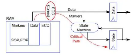
Fig. 1. Typical packet data storage in a networking application
In this thesis, a technique to enlarge a SEC code to too defend a few extra control bits is recommended. In the
resulting codes, the control bits may be decoded utilizing a division of the parity check bits. This decreases the
decoding delay and makes them appropriate for networking applications. To calculate the technique, several
codes have been constructed and implemented. They are then compared with existing solutions in terms of
de-coding delay and area.
II. DATA PROTECTION IN NETWORKING APPLICATIONS
Modern networking equipment maintains data rates that range from 10 to 400 Gbit/s, and terabit rates are
ex-pected in the near future. The clock frequencies used in current ASICs are normally in the collection of 300
MHz to 1 GHz, and the clock frequencies in FPGAs are typically lower (under 400 MHz). To maintain these
large data rates, on-chip packet data buses are large with usual widths among 64 and 2048 bits.
Packet data must frequently be stored in RAMs, e.g., in FIFOs for adapting processing rates.When storing
packet data, it is necessary to delineate the packet boundaries. In the absolute easiest case, every segment on the
bus can be defined by an only EOP marker. The subsequently suitable section is then imagined to be the begin
of the pursuing packet. In practice, designers also use a SOP marker to explicitly stain the begin of packets.
There are too several cases in packet developing wherever a packet is in error and it must be dropped. To mark
such erroredpackets, an additional control signal (ERR) may be required.
As mentioned in the introduction, from a fault protection view, it is striking to accumulate the information and
the indicators in a distinct large memory, as illustated in Fig. 1. Like this, fairly little ECC bits are needed. The
trouble with this approach is when the information are examine out. Normally, the indicators supply into a state
machine that manages the reading of the following data. For instance, the state machine can require to examine
out a single packet (up to an EOP), or it can require to examine out a fixed number of bytes of data (e.g., deficit
round robin scheduler). The critical timing path then consists of the ECC correction logic, followed by the state
machine logic, as illustarated in red. With a traditionalHamming SEC code, as the data bus increases in width,
the amount of layers of logic needed to decode the pattern and operate correction also enhances. Circuit
2558 |
P a g e
give downstream state machines. For this motivation, special ECC codes which can present a fast decode of theless number of indicator bits are very smart.
In various cases, it is sufficient for the structure to compact with the packet data with a granularity of the
ob-struct size. This prospective the case, for example, while the data are simply being transferred from one place to
another. On the other hand, in extra cases, it is significant to identify the packet data size a byte resolution. It
can be the case while the bit rate is essential (scheduling and policing) or when highest transfer unit length
checks are performed. The simple SOP and EOP indicators are not enough to know the exact packet with size;
thus, it may be necessary to store additional marker bits called EOPSIZE, which indicate how many of the bytes
in the EOP transfer are valid. Note that it is always assumed that all transfers prior to the EOP are complete. As
a result, on a 128-bit data bus, extra 4 bits of EOPSIZE can be needed, passing the total number of indicator bits
to 7 (SOP, EOP, ERR, and EOPSIZE[3:0]).
Fig. 2. Parity check matrix for a minimum-weight SEC code that protects 128 data bits
Fig. 3. Parity check matrix for a minimum-weight SEC code
that protects 128 data and 3 control bits
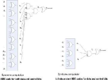
Fig. 4. Decoding of a control bit for single and independentSEC codes for data and control. (a) SEC code
for both data and control bits. (b) Independent SEC codes for data and control bits
2559 |
P a g e
III. PROPOSED METHOD TO DESIGN THE CODES
As explained in the introduction, the objective is to propose SEC codes that can defend a data block in addition
some control bits such that the control bits can be decoded with less delay. As declared earlier, the data blocks
to be defended have a range that is normally a power of two, e.g., 64 or 128 bits. To defend a 64-bit data
ob-struct with a SEC code, 7 parity check bits are needed, while 8 are enough to protect 128 bits. In the primary
case, there are 27 = 128 possible syndromes, and therefore, the SEC code may be extended to cover a few other
control bits. The similar is right for 128 bits and, in common, for a SEC code that defends a data obstruct that is
a power of two. It indicates that the control bits can also be defended with no extra parity check bits. It is more
efficient than using two separate SEC codes (one for the data bits and the other for the control bits) as this needs
extra parity check bits. The major difficulty in using an enlarged SEC code is that the decoding of the control
bits is extra difficult. To demonstrate this problem, let us think a 128-bit data obstruct and 3 control bits. The
first SEC code for the 128-bit data obstruct has the parity check matrix illustrated in Fig. 2. This code has a
parity check matrix with minimum total weight and balanced row weights to minimize encoding and decoding
delay. Three additional data columns can be easily added to find a code that protects the additional control bits.
For instance, the matrix in Fig. 3 can be used, in which three additional columns (marked as control bits) have
been added to the left.
The difficulty is that now, to decode the 3 control bits, we need to calculate the 8 parity check bits and compare
the results against the columns of the control bits. This is significantly more complex than the decoding of an
autonomous SEC code for the three control bits. The decoding of a bit in every case is represented in Fig. 4, and
the variation in intricacy is evident. As discussed former, our goal is to shorten the decoding of the control bits
while using a single SEC code for both data and control bits. To do so, the first step is to note that, in various
cases, SEC decoding can be simplified to check only some of the syndrome bits. One example is the decoding
of constant-weight SEC codes proposed. In this case, only the syndrome bits that have a 1 in the column of the
parity check matrix require to be checked. This simplifies the decoding for all bits but, in the majority cases,
needs extra parity check bits. In this case, the major intention is to shorten the decoding of the control bits as
those are commonly on the critical path. To do so, the parity check bits would be divided in two groups: a first
group that is allocated by both data and control bits and a second that is used only for the data bits. Then, the
decoding of the control bits only needs the recomputation of the primary collection of parity check bits. This
scheme is better shown with an example. Let us think a 128-bit data obstruct and 3 control bits protected with 8
parity check bits. Those 8 bits are divided in a collection of 3 shared between data and control bits and a second
group of 5 that is used only for the data bits. To defend the control bits, the first three parity check bits would be
allocated different values for each control bit, and the remaining parity check bits are not utilized to defend the
control bits. The rest of the values are exploited to protect the data bits, and for each value, different values of
the remaining five parity check bits can be used. In this example, the first group has 3 bits that can take 8
val-ues, and three of them are used for the columns that communicate to the control bits. This leaves 5 values that
would be exploited to defend the data bits. The second group of parity check bits has 5 bits that would be
uti-lized to code 32 values for all of the 5 values on the primary group. Therefore, a maximum of 5 × 32 = 160 data bits would be protected. In fact, the digit is lower as the zero value on the primary group would not be
2560 |
P a g e
one. In any case, 128 data bits would be simply protected. An example of the parity check matrix of a SEC codederived using this method is illustated in Fig. 5. The three first columns communicate to the added control bits.
The two groups of parity check bits are too separated, and the first three rows are shared for data and control
bits, while the previous five only defend the data bits. It can be inspected that the control bits would be decoded
by simply recalculating the first three parity check bits. Moreover, the zero value on these three bits is also used
for some data bits. This indicates that those bits are not required to recompute the first three parity check bits.
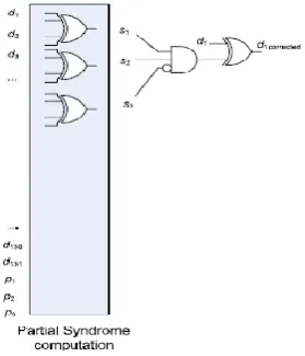
Fig. 6. Bit decoding of a control bit in the proposed SEC code
Table 1 Minimum number of P
cdbits for 128 and 256 data bits
Fig. 7. Proposed parity check matrix for a SEC
code that protects 128 data and 7 control bits
The decoding of one of the control bits is illustrated in Fig. 6. It would be examined that the circuitry is
signifi-cantly simpler than that of a traditional SEC code (see left part of Fig. 4). This will be confirmed by the
practic-al results presented in the subsequently section.
The method would also be utilized to defend more than three control bits. In a general case, let us think that we
require to defend d data bits and c control bits using p parity check bits. Then, p is divided in two groups pcdand
pd. The primary group is shared between control and data bits, and the second is used only for the data bits. The amount of data bits that can be defended with this scheme would be estimated as follows. The number of
2561 |
P a g e
values with weight one on the primary group, the zero value on the second group cannot be used as the resultingcolumn would have weight one. Therefore, pcdshould also be subtracted, presenting a total of (2Pcd − c) · 2Pd − (pd+ 1) − pcd. It is the amount of data bits that would be defended in addition to the control bits. As the figure of
control bits increases, pcd must also be increased to be capable to defend the obstruct of data bits with the similar amount of parity check bits. It is illustrated in Table 1 for 128 and 256 data bits. Enhancing pcd makes the de-coding of control bits more complex; therefore, the minimum significance would be used.
For example, the parity check matrix to protect 128 data and 7 control bits is illustrated in Fig. 7. It can be
ex-amined that, in this situation, more bits are needed in the primary group, making the decoding of the control bits
a little extra difficult. On the other hand, the control bits would still be decoded utilizing only four syndrome
bits in place of the eight bits needed in a traditional SEC code. Finally, it should be noted that the proposed
scheme raises the miscorrection probability for control bits in case of double errors. This is due to the utilize of
only a division of bits for the decoding of the control bits.
IV. SYNTHESIS AND SIMULATION RESULTS
The proposed SEC decoder is designed with the XILINX ISE 14.5 simulation tool and implemented with
Verilog HDL. The RTL diagram and simulation results are displayed below.
Fig. 8: Top level schematic diagram
2562 |
P a g e
Fig. 10: Synthesis report
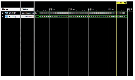
Fig. 11: Simulation result
V. CONCLUSION
In this thesis, we have proposed a scheme to construct SEC codes that can defend an obstruct of data and some
extra control bits has been presented. The obtained codes are designed to enable fast decoding of the control bits.
The derived codes have the similar amount of parity check bits as existing SEC codes and therefore do not
re-quire additional cost in terms of memory or registers. To evaluate the benefits of the proposed scheme, several
codes have been implemented and evaluated with minimum-weight SEC codes.
VI. FUTURE SCOPE
This scheme can be extended to support more control bits by utilizing single or two extra parity check bits. This
would provide a solution to achieve fast decoding without using two split codes for data and control bits.
REFERENCES
[1] P. Bosshart et al., ―Forwarding metamorphosis: Fast programmable match-action processing in hardware
for SDN,‖ in Proc. SIGCOMM, 2013, pp. 99–110.
[2] J. W. Lockwood et al., ―NetFPGA—An open platform for gigabit-rate network switching and routing,‖ in
Proc. IEEE Int. Conf. Microelectron.Syst. Educ., Jun. 2007, pp. 160–161.
[3] A. L. Silburt, A. Evans, I. Perryman, S.-J. Wen, and D. Alexandrescu, ―Design for soft error resiliency in
2563 |
P a g e
[4] E. Fujiwara, Code Design for Dependable Systems: Theory and Practical Application. Hoboken, NJ,USA:Wiley, 2006.
[5] C. L. Chen and M. Y. Hsiao, ―Error-correcting codes for semiconductor memory applications: A
state-of-the-art review,‖ IBM J. Res. Develop., vol. 28, no. 2, pp. 124–134, Mar. 1984.
[6] V. Gherman, S. Evain, N. Seymour, and Y. Bonhomme, ―Generalized parity-check matrices for SEC-DED
codes with fixed parity,‖ in Proc.IEEE On-Line Test. Symp., 2011, pp. 198–20.
[7] Ten Gigabit Ethernet Medium Access Controller, OpenCores. [Online]. Available:
http://opencores.org/project/ethmac
[8] P. Zabinski, B. Gilbert, and E. Daniel, ―Coming challenges with terabitper-second data communication,‖
IEEE Circuits Syst. Mag., vol. 13, no. 3, pp. 10–20, 3rd Quart. 2013.
[9] UltraScale Architecture Integrated Block for 100 G Ethernet v.14. LigCOREIP Product Guide. PG165,
Xi-linx, San Jose, CA, USA. Jan. 22, 2015.
[10] OpenSilicon Interlaken ASIC IP Core. [Online]. Available: www.opensilicon.
com/open-silicon-ips/interlaken-controller-ip/
AUTHOR DETAILS
MOHIYA TABASSUM, pursuing M.Tech (DSCE) from Sri Visvesvaraya Institute
Of Technology & Science, Chowderpally (Vill), Devarkadra (Mdl), Mahabubnagar
(Dist), TS, INDIA.
K. RAJESH KUMAR, working as Assistant professor (ECE) from Sri
Visvesva-raya Institute Of Technology & Science, Chowderpally (Vill), Devarkadra (Mdl),