ISSN (Print) : 2320 – 3765 ISSN (Online): 2278 – 8875
I
nternational
J
ournal of
A
dvanced
R
esearch in
E
lectrical,
E
lectronics and
I
nstrumentation
E
ngineering
(An ISO 3297: 2007 Certified Organization)
Website: www.ijareeie.com Vol. 6, Issue 3, March 2017
Renewable Energy Source Compensator for
Power Quality Issues Using Active Power
Filter in Grid
R.Mahendran1, M.Rajasekar2, P.Swadeeswaran3, M.Vignesh4,
Assistant Professor, S.A. Engineering College, Chennai, India1
UG Scholar, S.A. Engineering College, Chennai, India 2, 3, 4
ABSTRACT: Renewable energy sources are a dependable different to the predictable energy sources. This paper presented an capable of inflatable grid-connected spreading generation interconnection of 3 phase 3 wire system for reactive power compensation. In this proposed system, we can control mitigate the load unbalance, harmonics, and manage reactive power and also the active authority flow. All of these functions may be accomplished either individually or simultaneously. So the performing an active power balance by controlling the RES voltage level for the whole system. With the proposed approach, to shape the grid currents into sinusoidal currents in phase with the grid voltage waveforms and with an amplitude depending on the power available from renewable sources. On the other hand the load harmonics current will reduced by injecting into the alternating current system harmonic currents with an opposite phase.
KEYWORDS: Renewable Energy Sources (RES), Active Power Filter (APF), Power Quality (PQ), Grid Interconnection.
I. INTRODUCTION
he load will be changed in nonlinearly then the reactive power compensation will be increased so the power system losses are increased. Due to this nonlinear load the current harmonics are increases in the transmission lines, rotating machines, and transformers. Furthermore, harmonics and unbalance load causes the oscillatory torque in the sensitive equipment it's leading to malfunctions of the equipment’s, and also interference with communication circuits. So to overcome these harmonics current by using the Active Power Filter(APF) which have been successfully developed [1],[2].
Resent days the fossil fuel is the most important role in the energy generation, but its lead to a major environmental problems so to avoid these problems the mankind to look for alternative resources in power generation[3]. Interest in renewable energy is increasing due to concerns about pollution, global warming, air quality, and sustainability.Renewable energy source (RES) integrated at the distribution level is termed as distributed generation (DG) the current controlled voltage source inverters are used to interface the intermittent RES in distributed system[4]. To perform the active power flow control there is no need of External hardware devices of the proposed method. The Renewable generating units with the active filter capability may play an significant role in power quality management in upcoming power systems.
ISSN (Print) : 2320 – 3765 ISSN (Online): 2278 – 8875
I
nternational
J
ournal of
A
dvanced
R
esearch in
E
lectrical,
E
lectronics and
I
nstrumentation
E
ngineering
(An ISO 3297: 2007 Certified Organization)
Website: www.ijareeie.com Vol. 6, Issue 3, March 2017
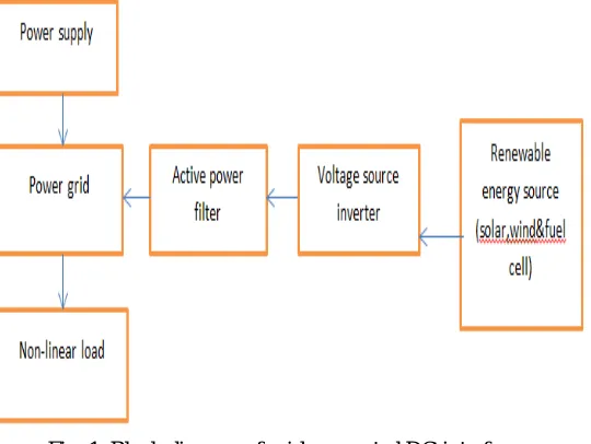
Fig. 1. Block diagram of grid-connected DG interface.
From these block diagram shown in fig. 1, the DG source are like as a solar (pv), wind and fuel cell, etc. and the converter is a bipolar voltage source inverter and the nonlinear load.
To interconnect the Distribution Generation(DG) units with the Active Power Filter(APF) capability and two separate controllers have been designed for the DG interface[5] wherein the Solar(PV) system can act as a solar power generator on sunny days and an APF on rainy days. An APF applications the reference current is generated by using less computation time and some stored coefficients if compared with those mandatory by the DFT[6]. Conventional DGs are based on renewable energy sources require a power electronic converter to interfacing with the utility grid because the generated power is DC or has an AC frequency that is either non constant or higher than the grid frequency[7]. Based on local measurement and agent-based communication, the power electronic converters were designed to provide non-active power in addition to active power supply in order to compensate distorted current[8]. Using adaptive neural straining for harmonic analysis, a single-phase DG system with active power filtering capability was devised for utility current harmonic compensation [9].
ISSN (Print) : 2320 – 3765 ISSN (Online): 2278 – 8875
I
nternational
J
ournal of
A
dvanced
R
esearch in
E
lectrical,
E
lectronics and
I
nstrumentation
E
ngineering
(An ISO 3297: 2007 Certified Organization)
Website: www.ijareeie.com Vol. 6, Issue 3, March 2017
II. GRID CONNECTED DG SYSTEM
In this paper, the Distributed Generation(DG) is interconnected to the Three-Phase grid with the help of the Active Power Filter.
A) Non-Linear Load
The nature of non-linear loads has to produce harmonics in the current waveform so the current waveform will be distorted and this distortion leads to distortion of the voltage waveform. For these conditions, the voltage waveform is no longer depends to the current. This load current contains all ODD harmonics. It is Can’t be categorized as leading or lagging Loads. If the load is considered as a non-linear load its impedance changes with the supply voltage. At the time of impedance changing that the current drawn by the non-linear load will not be sinusoidal even when it is connected to a sinusoidal voltage. This non-sinusoidal current contains the harmonic currents that will interact with an impedance of the power distribution system to create the voltage distortion that can affect both the loads connected to it and the distribution system equipment. Essentially very high inrush current (20 time of I Normal) at the time of starting. For examples of the non-linear loads are like as a Computers, laser printers, SMPS, TV, Rectifiers, Refrigerator, etc.
B) Distribution Generation(DG)
Now a days the available level of the natural resources (coal, natural gases and oil, etc.) are reduced and also it is the major causes of the environmental pollutions. So we need to move an alternative sources of renewable sources for the power generation. Normally the renewable sources are solar, wind, hydro, fuel cells, etc. For this paper the solar (PV) and wind energy is used as a DG.
In this paper, a unified control method is proposed for a simple three-phase DG interface with a series diode for preventing power reversal to transmit active power, mitigate load unbalance and harmonics, and compensate reactive power. So the DG can perform the two functions of power station and APF as simultaneously or either one.
III. SHUNT ACTIVE POWER FILTER
In recent years, the power electronic converters are widely used in industrial and as well as domestic applications for the control of power flow. These converters take the advantages of all the recent advances and improvements of power electronics; affect from the problem of drawing non-sinusoidal current and reactive power from the supply. Their contributions to the waveform distortion is of growing interest, and are responsible for different power quality problems, led to implementation of standards and guidelines such as IEEE-519. Active power filters(APFs) are researched and developed as a viable alternative over the conventional methods to solve these problems [1], [2]. The APF can compensate harmonics and reactive power requirement of the nonlinear load effectively. Presently, APFs are designed to absorb all of the harmonics generated and/or reactive power required by the load and make the source current sinusoidal. The size and cost of APF depends on harmonics and reactive power to be compensated.
ISSN (Print) : 2320 – 3765 ISSN (Online): 2278 – 8875
I
nternational
J
ournal of
A
dvanced
R
esearch in
E
lectrical,
E
lectronics and
I
nstrumentation
E
ngineering
(An ISO 3297: 2007 Certified Organization)
Website: www.ijareeie.com Vol. 6, Issue 3, March 2017
IV.SIMULATION RESULT
The proposed APF was studied using simulation tools and advanced continuous simulation language (ACSL). Table I shows system parameters and load conditions under the unbalance.
TABLE I
SYSTEM PARAMETERS
Line- to- neutral grid voltage 440v
Grid frequency 50Hz
Filter inductor 1mH
IPM module PM15CSJ060
Switching Frequency 15KHz
DC Capacitor 6600µF
Time constant for Low Pass Filter 0.06ms
DG Voltage 0-360V
DG Resistor 10Ω
DC link voltage 1200V
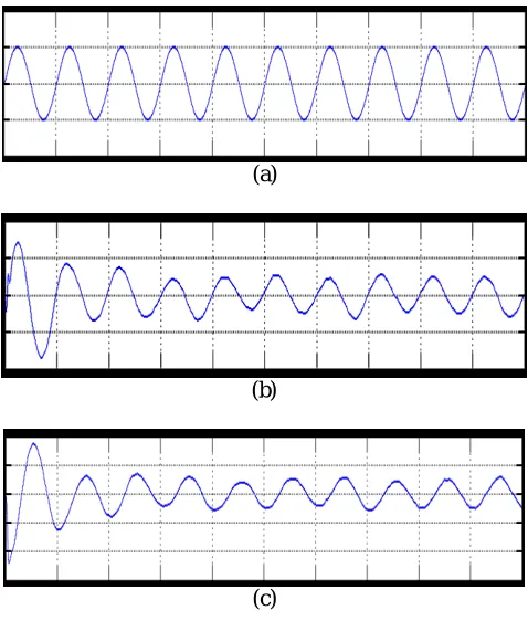
First consider the linear load condition at the time the following experimental result will be found, it’s shown in the fig. 2, and 3, from these graph when the load will be changed as linearly then the source side power flow will be linearly that is source side voltage and current is sinusoidal at the time the reactive power compensation is not required. And the capacitor will be charged for their maximum value. In here the capacitor value is set as 6600 micro farad. From these simulation outcome we can analyse the system performance of the overall power system network.
(a)
(b)
ISSN (Print) : 2320 – 3765 ISSN (Online): 2278 – 8875
I
nternational
J
ournal of
A
dvanced
R
esearch in
E
lectrical,
E
lectronics and
I
nstrumentation
E
ngineering
(An ISO 3297: 2007 Certified Organization)
Website: www.ijareeie.com Vol. 6, Issue 3, March 2017
(d)
Fig. 2, APF response when the load is linear condition
(a). R phase Grid Voltage, (b). R phase Grid current, (c).Y phase Grid current, (d)DC link voltage.
(a)
(b)
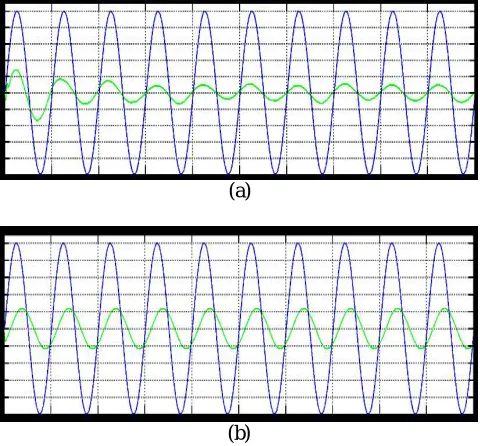
Fig. 3, (a) Source voltage & current at linear load (b) Load voltage ¤t at linear load
(a)
ISSN (Print) : 2320 – 3765 ISSN (Online): 2278 – 8875
I
nternational
J
ournal of
A
dvanced
R
esearch in
E
lectrical,
E
lectronics and
I
nstrumentation
E
ngineering
(An ISO 3297: 2007 Certified Organization)
Website: www.ijareeie.com Vol. 6, Issue 3, March 2017
(c)
(d)
Fig. 4, APF response when the load is non-linear condition
(a). R phase Grid Voltage, (b). R phase Grid current, (c).Y phase Grid current, (d).DC link voltage.
(a)
(b)
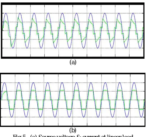
Fig.5, (a) Source voltage & current at linear load (b) Load voltage ¤t at linear load
If consider the non-linear load condition at the time the following experimental result will be obtained, it’s shown in the fig. 4, and 5, from these graph when the load will be changed as non-linearly then the source side power flow will be non-linearly that is source side voltage and current is non-sinusoidal at the time the reactive power compensation is required. And the capacitor will be discharged for their minimum value. From these simulation result we can analyse the system performance of the overall power system network at non-linear load condition.
V. EXPERIMENTAL RESULT
ISSN (Print) : 2320 – 3765 ISSN (Online): 2278 – 8875
I
nternational
J
ournal of
A
dvanced
R
esearch in
E
lectrical,
E
lectronics and
I
nstrumentation
E
ngineering
(An ISO 3297: 2007 Certified Organization)
Website: www.ijareeie.com Vol. 6, Issue 3, March 2017
circuit are listed in Table I. A three phase rectifier fed a resistor in series with capacitor used as the nonlinear load and another resistor connected between A- and C-phase used as the unbalanced load. To demonstrate the proposed system as a power control station, an experiment was conducted. Fig. 2 and 3 shows performance of the DG interface with no local nonlinear load at VDG = 340V. It can be seen that the three-phase grid currents were sinusoidal and in phase with the grid voltages.an experiment with unbalanced nonlinear loads and no DG was conducted. Fig. 4 and 5 shows the waveform and spectrum of local nonlinear load currents. The three-phase load currents were unbalanced.
(a)
(b)
Fig. 6, (a). Power factor in source side at Non-linear load condition. (b). THD analysis = 3.31%
From fig. 6 shows The grid current produced an almost-unity power factor of 0.98, and its total harmonic distortion (THD) was about 3.31%. In order to illustrate the load balancing and harmonic compensation capability of the proposed system as an APF.
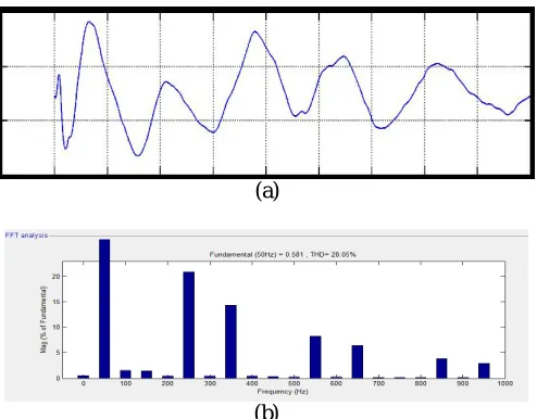
(a)
(b)
Fig. 7, (a). Power factor in source side at Linear load condition, (b). THD analysis =28.05%.
ISSN (Print) : 2320 – 3765 ISSN (Online): 2278 – 8875
I
nternational
J
ournal of
A
dvanced
R
esearch in
E
lectrical,
E
lectronics and
I
nstrumentation
E
ngineering
(An ISO 3297: 2007 Certified Organization)
Website: www.ijareeie.com Vol. 6, Issue 3, March 2017
conducted. To demonstrate the dynamic response of the proposed system, the VDG was changed from 320 to 360V and there was no local load.
VII. CONCLUSION
A unified control method for the DG interface is proposed in this paper. The proposed method allows the utilization of DG to generate active power, eliminates harmonics, compensates reactive power, and mitigates load unbalance. Therefore, its multifunctional behaviour replaces the need for other power electronics compensators to enhance the performance of the distribution networks. With this proposed approach, to shape the grid currents into sinusoidal currents in phase with the grid voltage waveforms and with an amplitude depending on the power available from renewable sources. On the other hand the load harmonics current will reduced by injecting into the alternating current to system harmonic currents with an opposite phase. In this manner, controlling the dc voltage level can be equivalent to performing an active power balance for the whole system. As a result, there is a additional hardware and interface are not required. Experimental results verified the effectiveness of the proposed method.
REFERENCES
[1]. Sangu Ravindra, Dr.V.C.Veera Reddy, and Dr.S.Sivanagaraj “Design of Shunt Active Power Filter to eliminate the harmonic currents and to compensate the reactive power under distorted and or imbalanced source voltages in steady state” International Journal of Engineering Trends and Technology- Volume2Issue3- 2011.
[2]. Maoh-Chin Jiang “Analysis and Design of a Novel Three-Phase Active Power Filter” IEEE Transactions on Aerospace and Electronic Systems vol. 37, no. 3 July 2001.
[3]. Frede Blaabjerg, Marco Liserre, and Adrian V. Timbus, “Overview of Control and Grid Synchronization for Distributed Power Generation Systems” IEEE Transactions on Industrial Electronics, vol. 53, no. 5, October 2006.
[4]. Mukhtiar Singh, Vinod Khadkikar, Ambrish Chandra, and Rajiv K. Varma, “Grid Interconnection of Renewable Energy Sources at the Distribution Level With Power-Quality Improvement Features” IEEE Transactions on Power Delivery, vol. 26, no. 1, January 2011.
[5]. Y.-C. Kuo, T.-J. Liang, and J.-F. Chen, “A high-efficiency single-phase three-wire photovoltaic energy conversion system,” IEEE Trans. Ind. Electron., vol. 50, no. 1, pp. 116–122, Feb. 2003.
[6]. S. A. Gonzalez, R. Garcia-Retegui, and M. Benedetti, “Harmonic computation technique suitable for active power filters,” IEEE Trans. Ind. Electron., vol. 54, no. 5, pp. 2791–2796, Oct. 2007.
[7]. J.M. Carrasco, L. G. Franquelo, and J. T. Bialasiewicz, “Power-electronic systems for the grid integration of renewable energy sources: A survey,” IEEE Trans. Ind. Electron., vol. 53, no. 4, pp. 1002–1016, Aug. 2006.
[8]. K. J. P. Macken, K. Vanthournout, and J. Van deneybus, “Distributed control of renewable generation units with integrated active filter,” IEEE Trans. Power Electron., vol. 19, no. 5, pp. 1353–1360, Sept. 2004.
[9]. M. Cirrincione, M. Pucci, and G. Vitale, “A single-phase DG generation unit with shunt active power filter capability by adaptive neural filtering,” IEEE Trans. Ind. Electron., vol. 55, no. 5, pp. 2093–2110, May 2008.
[10].C. J. Gajanayake, D. M. Vilathgamuwa, P. C. Loh, R. Teodorescu, and F. Blaabjerg, “Z-source-inverter-based flexible distributed generation system solution for grid power quality improvement,” IEEE Trans. Energy. Convers., vol. 24, no. 3, pp. 695–704, Sept. 2009.
[11].P.-T. Cheng, C.-A. Chen, T.-L. Lee, and S.-Y. Kuo, “A cooperative imbalance compensation method for distributed-generation interface converters,” IEEE Trans. Ind. Appl., vol. 45, no. 2, pp. 805–815, Mar./Apr. 2009
[12].P. Hsu and M. Behnke, “A three-phase synchronous frame controller for unbalanced load,” in Proc. 29th Annu. IEEE Power Electron. Spec. Conf., 1998, pp. 1369–1374.
[13].M. I. Marei, E. F. El-Saadany, and M. M. A. Salama, “A novel control algorithm for the DG interface to mitigate power quality problems,” IEEE Trans. Power. Deliver., vol. 19, no. 3, pp. 1384–1392, Jul. 2004.
[14].Y. Li, D. M. Vilathgamuwa, and L. P. Chiang, “Microgrid power quality enhancement using a three-phase four-wire grid-interfacing compensator,” IEEE Trans. Ind. Appl., vol. 41, no. 6, pp. 1707–1719, Nov./Dec. 2005.
[15].H. S. Song and K. H. Nam, “Dual current control scheme for PWM converter under unbalanced input voltage conditions,” IEEE Trans. Ind. Elec., vol. 46, no. 5, pp. 953–959, Oct. 1999.
[16].W. C. Lee, T. K. Lee, and D. S. Hyun, “A three-phase parallel active power filter operating with PCC voltage compensation with consideration for an unbalanced load,” IEEE Trans. Power Electron., vol. 17, no. 5, pp. 807–814, Sept. 2002.
[17].Mi-Ching Tsai, and Wu-Sung Yao “Design of a Plug-In Type Repetitive Controller for Periodic Inputs” IEEE Transactions on Control Systems Technology, vol. 10, no. 4, july 2002.