Design of PMSG Based Wind Energy
Conversion System with Unified Power
Controller
Prof A.S Shajilal1, Rudra J Kumar2
Professor, Dept of EEE, Mar Baselios College of Engineering and Technology, Trivandrum, Kerala, India1 PG Student , Dept of EEE, Mar Baselios College of Engineering and Technology, Trivandrum, Kerala, India2
ABSTRACT:. In this paper a unified power controller is designed covering the whole range of wind speed for variable speed fixed pitch wind energy conversion system(WECS).The proposed controller consists of a modified maximum power point tracking(MPPT) controller in low wind speed and a new constant speed and constant power controller in high wind speed. For the former combination of Hill Climb Searching (HCS) and power signal feedback method (PSF) MPPT algorithms are used. The modified HCS method is activated to find MPP, once an MPP is found it switches to PSF method. By using this low power/torque ripple is achieved. A new auxiliary stall method is proposed for the latter. It temporarily increases the output power to force the turbine to operate in deep stall regime, thus to decrease the captured power of turbine. Among all the available wind turbine generators, permanent magnet synchronous generators are developing very fast because it uses direct drive structure which avoids the use of gear box and increases the system stability. The simulations are performed using MATLAB/SIMULINK software and the results are presented.
KEYWORDS: Maximum power point tracking, Wind energy conversion system, Permanent magnet synchronous generator, Unified power controller.
I. INTRODUCTION
In recent years, due to the fast depleting conventional energy resources and the concerns over climatic changes, the renewable energy sources are gaining popularity around the globe. Due to large depletion of fossil fuels and climatic changes it is strongly recommended to depend on nonpolluting ways to produce energy. Among all the available renewable energy resources wind energy is wind energy is by far one of the fastest growing energies due to policies fostering and technical maturity[1,2].Permanent magnet synchronous generator is developing very fast among all available wind turbines. It avoids the use of gear box because it can be used to form a direct-drive structure which can avoid the use of gearbox and increase the system reliability. Therefore, the direct drive wind energy conversion system (WECS) using PMSG has received much attention worldwide [4].
The power quality problems can be checked with wind generation, transmission and distribution power networks, like voltage sag, swells, flickers, harmonics etc. Distribution network is being disturbed with the wind generator. One method is to use induction generator which is directly connected to the grid power system. The induction generator has great advantages of cost effectiveness [2]. Permanent magnet synchronous generator (PMSG) is used for wind power generating system because of its many advantages such as better efficiency, lower maintenance, and reliability. The PM machines have many advantages which includes higher reliability, higher efficiency and energy yield, Lower maintenance cost. To maximize profit by increasing annual energy yields is the basic goal of control system for WECS. In order to obtain this, WECS is usually controlled to generate power following a curve called ideal
Fig 1: Ideal power curve
The above given diagram represents the ideal power curve. It can be observed from the above diagram that there are mainly 3 regions included. They are Region I (MPPT region), Region II (Constant speed), Region III (Constant Power region).
By regulating tip speed ratio, tip speed method is realized which is calculated real time using wind speed and generator speed signals to follow a preobtained value. Even though the method is simple, it is avoided from the industry due to detecting wind speed [6]. By perturbing generator, HCS method directs the system to maximum power point (MPP)[7-8].
It advantages low cost, no need of knowing aerodynamic characteristics of turbine, ease implementation. It has advantages of deteriorated power quality, as power ripple exists at low tracking speed. PSF is activated only if an aerodynamic characteristic of wind turbine is known. So it is impossible for finding MPPT. The generator speed and power would exceed the limit in high speed wind region, if MPPT control method is still used. It is much convenient and simple to limit the speed especially power for variable-pitch wind turbine because there is possibility of pitch regulation. Pitch control with active stall or pitch whenever overloading or over speeding occurs. The MPP searching process automatically recovers once the over speeding and overloading are relieved. After one MPP is found, the controller switches to PSF MPPT method to achieve low tracking torque/power ripple and fast tracking speed. In high wind speed region, the proposed controller uses a new constant power soft-stalling method to limit the turbine power. The proposed method is quite general and also easily implementable. The rest of this paper is organized as follows: the system structure is briefly introduced in Section II. In Section III, the proposed power controller, including the advanced MPPT controller and the constant speed and constant power controller, are studied in detail. In Section IV, the dc-link voltage regulator, which is a key unit in the proposed controller, carefully designed to ensure good system performance.
II. SYSTEM CONFIGURATION
used. Boost converter is used to regulate the turbine power by adjusting duty ratio. The aerodynamic power is given by the equation
Pm= 0.5Cp(β,λ)ρA(Vw)
3
(1)
Where Cp is Power Coefficient, A is area of rotor blade, β is pitch angle, λ is tip speed ratio, Vw is wind velocity.
Fig2: Basic block diagram of system
For a fixed-pitch wind turbine, Cpis only a function of the tip-speed-ratio λ, which is determined by
λ = ( Rω/vw) (2)
Fig 3: Cp- λ curve for typical turbine blades
III. PROPOSED CONTROLLERS
in deep stall regime thereby decreasing the output power of turbine.The detailed flowchart of the proposed controllers are given in the below flowchart.
Fig4: Flowchart of proposed controller
IV. WIND TURBINE MODELLING
The wind turbine consists of classic three bladed horizontal-axis, wind turbine system with the corresponding pitch controller. The output mechanical power is given by the equation
Pm= Cp(β,λ) ρA/ 2(Vw)3 (3)
Where Pm = Turbine mechanical output power Cp= Performance coefficient of turbine
ρ= Air density (Kg/m3),
λ= Tip speed ratio A= swept area of turbine β= blade pitch angle Vw= wind speed (m/s)
The power coefficient Cp is a nonlinear function of the blade pitch angle β and the tip-speed ratio λ as given by
λ = ( Rωm/vw) (4)
Where, ωm - Angular speed of the turbine rotor
R - Radius of the turbine blades
V.PITCH ANGLE CONTROLLER
VI.TWO MASS DRIVE TRAIN MODEL
This Model shows the combination of wind turbine and shaft side. The differential equations are representing its mechanical dynamics which are given below
2Ht dwt /dt =Tm – Tsh (5)
1/welb *dθtw/dt = wt – wr (6)
2Hgdwr/dt = Tsh – Tg (7)
Where Ht = inertia constant of the turbine,
Hg= inertia Constant of the PMSG,
θtw = shaft twist angle,
wt = Angular speed of the wind turbine in p.u.
wr = rotor speed of the PMSG in p.u.
welb = electrical base speed
The Shaft torque Tsh is
Tsh = Ksh θtw +Dt dθtw/dt (8)
Where Ksh = shaft stiffness Dt = damping coefficient.
VII.PERMANENT MAGNET SYNCHRONOUS MACHINE
The permanent magnet synchronous machine works as a generator .The second order state space model is represented with electrical and mechanical parts of this machine. The sinusoidal model assumes that the flux established by the permanent magnet is sinusoidal which further implies that emf is also sinusoidal. These equations are represented in rotor reference frame .All quantities in the rotor reference frame referred to the stator.
VIII.SIMULINK MODEL AND SIMULATION RESULTS
Fig 5 shows the model of wind turbine The wind turbine consists of classic three bladed horizontal-axis, wind turbine system with the corresponding pitch controller.
Fig 5: Simulink model of wind turbine
When the wind velocities are higher than rated, the maximum energy captured must be limited using pitch control by modifying β.
Fig 6:Simulink model of pitch angle controller.
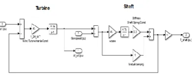
Fig 7, shows the Model shows the combination of wind turbine and shaft side.
Fig 7:Simulink model of 2 mass drive train
Fig 8 shows the model It converts mechanical power output of wind turbine into electrical power. Principle: Faradays law of electromagnetic induction. Can be extremely large- power rating up to 1500MW.They are known as Synchronous machine because they operate at synchronous speed(Speed of rotor always matches with supply frequency)Ns=120f/p.Instead of field winding, Permanent magnet is used in rotor. Doesn’t require DC supply.
Fig 8:Simulink model of PMSG
Fig 9: Simulink model of pmsg connected WECS
Fig 10: Simulink model of closed loop control of PMSG connected to wind turbine diode bridge and controller
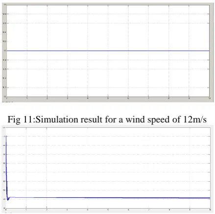
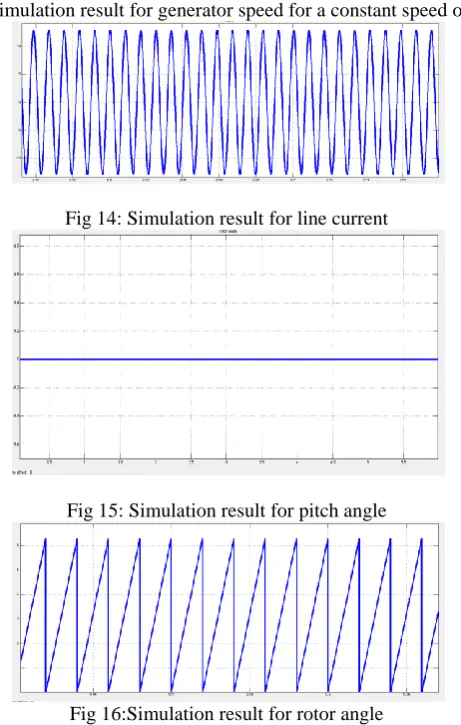
Fig 11 shows simulation result for wind speed of 12m/s, Fig 12 shows electromagnetic torque, Fig 13,shows corresponding generator speed, Fig 14 shows generated line current, Fig 15 shows corresponding pitch angle,Fig 16 shows rotor angle
Fig 11:Simulation result for a wind speed of 12m/s
Fig 13:Simulation result for generator speed for a constant speed of 12m/s
Fig 14: Simulation result for line current
Fig 15: Simulation result for pitch angle
Fig 16:Simulation result for rotor angle
Fig 17:Simulation result for closed control of WECS connected to diode bridge and boost and controller for a constant speed of 12m/s
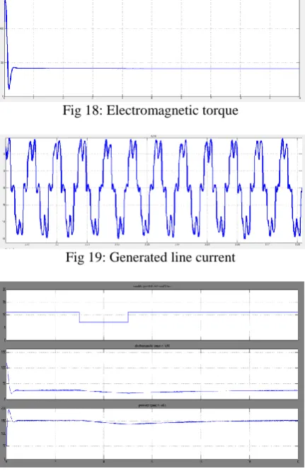
Fig 18: Electromagnetic torque
Fig 19: Generated line current
Fig 21:Simulation result for closed control of WECS connected to diode bridge and boost and controller for a variable speed of 7m/s and 11 m/s, corresponding power curve.
XI.CONCLUSION
The simulations of pmsg based WECS with unified power controller is presented here and corresponding results are obtained. The unified power controller includes 3 controllers in 3 regions. As a result of this controller low torque and power ripple is achieved
REFERENCES
[1] C. N. Bhende, S. Mishra, Siva Ganesh Malla, “Permanent Magnet Synchronous Generator-Based Standalone Wind Energy Supply System” IEEE Transactions On Sustainable Energy, Vol. 2, No. 4, October 2011, pp 361 – 373
[2] W.Leonhard, Control of Electrical Drives, 2nd ed. Berlin, Germany: Springer-Verlag, 1996
[3] S. Venkatraj and G. Mohan, “Modeling of Wind Farms with Variable Speed Direct Driven Permanent Magnet Synchronous Generator Wind Turbine” International Journal of Research and Reviews in Electrical and Computer Engineering (IJRRECE), Vol 1, No 3, pp 982-990, September 2011
[4] Alejandro Rolan', Alvaro Luna, Gerardo Vazquez, Daniel Aguilar, “Modeling of a Variable Speed Wind Turbine with a Permanent Magnet Synchronous Generator” IEEE International Symposium on Industrial Electronics (ISlE 2009,) July 5-8, 2009, pp 734 – 739
[5] K. Vinoth Kumar, Prawin Angel Michael, Joseph P. John and Dr. S. Suresh Kumar “ Simulation and Comparison of SPWM and SVPWM Control for three phase inverter” ARPN Journal of Engineering and Applied Sciences, Vol. 5, No. 7, July 2010, pp 61 – 74
[6] D. Sandhya Rani , A.Appaprao, “A Space Vector PWM Scheme for Three level Inverters Based on Two-Level Space Vector PWM” , International Journal Of Power System Operation and Energy Management (IJPSOEM) Volume-1, Issue-1, 2011, pp 6 – 10
[7] Aryuanto Soetedjo, Abraham Lomi, Widodo Puji Mulayanto, “Modeling of Wind Energy System with MPPT Control” International Conference on Electrical Engineering and Informatics, 17-19 July 2011, E4