Gain Enhancement and Wideband RCS Reduction of a Microstrip
Antenna Using Triple-Band Planar Electromagnetic
Band-Gap Structure
Yang Li1, *, Kunzhe Zhang1, Lin-An Yang1, and Lin Du1
Abstract—A triple-band planar electromagnetic band-gap (EBG) structure used for gain enhancement and wideband radar cross section reduction (RCSR) of antenna is presented in this paper. Three band-gaps of an EBG structure are realized by introducing two planar spiral inductances on a planar EBG structure. An equivalent model of EBG is given to further understand the formation of three band-gaps. The proposed EBG is placed around antenna units and arrays to calculate the affection of the RCS and the gain. Due to the band-gaps of the EBG structure, RCS of antennas is reduced, and the gain of antennas is enhanced. Results show that the RCS is reduced as much as 20 dB from 9 GHz to 21 GHz, and both of bandwidth and gain of antennas can be slightly enhanced. Two antenna units operating at 8.6 GHz are fabricated and measured to verify the correctness of simulation. Measured and simulated results are in good agreement.
1. INTRODUCTION
In recent years, reducing the radar cross section (RCS) of antenna has received more and more attention because the antenna is usually an efficient scatterer [1]. Lots of methods for RCS reduction of antennas have been presented over the past decades [2–7], such as the using of absorbing material, resonance structures, and slot technologies. In [8], an X-shaped absorbing material is used for RCS reduction, and the RCS of antenna can be reduced up to 14 dB. However, radiation performance of the antenna is also deteriorated due to the absorbing material. In [9], lumped elements are loaded on an antenna to realize RCS reduction but at the expense of gain. In recent years, electromagnetic band gap (EBG) and frequency selective surface (FSS) have been presented to achieve low RCS antenna. A mushroom-like EBG structure is used to reduce the RCS of patch antenna in [10]. A maxim reduction of 30 dB is achieved. Li et al. combine EBG structure and absorbing material to realize the RCS reduction of a waveguide slot antenna [11]. In [12], EBG structure is used to reduce in-band RCS of a patch antenna and the RCS decreased more than 10 dB at the operation frequency. By using FSS ground instead of traditional solid metal ground, the RCS of antenna can be reduced [13–16]. But due to the replacement of the ground, the power leakage reduces the gain all the same. In fact, methods mentioned above have some limitations. Some of them can only realize narrow-band RCSR, and some of them reduce the gain more or less. It is highly hoped that the RCS can be reduced within a wideband frequency range while the gain of antenna can be enhanced at the same time.
In this paper, a triple-bands EBG structure realized by adding two planar spiral inductances on a conventional planar EBG structure is used to reduce the RCS and enhance the gain of antenna. Equivalent model and field distribution are shown to further understand the realization of three band-gaps. Three band-gaps are in cascade so that the RCS can be reduced in a broad range of frequency.
Received 8 November 2016, Accepted 30 December 2016, Scheduled 20 January 2017
* Corresponding author: Yang Li (yli [email protected]).
The radiation performance of antenna is also enhanced due to the existence of surface wave band-gaps. Results show that the RCS can be reduced in a wide bandwidth from 9 GHz to 21 GHz, and the gain of antenna is well enhanced.
2. DESIGN OF EBG
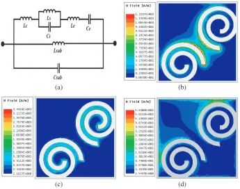
The geometry of the proposed EBG is shown in Fig. 1. The EBG is designed on a printed circuit board (PCB) substrate with thickness of 1.5 mm andεr= 2.2. Two spiral inductances are added to the conventional mushroom-like EBG structure (without via-hole to ground) to form the three band-gaps. Planar inductances are symmetric about the origin in order to obtain similar frequency responses in TE-polarized and TM-polarized wave. Fig. 2(a) shows the equivalent model of EBG. Lsub and Csub
Figure 1. Geometry of EBG (unit in mm).
(a) (b)
(c) (d)
are the inductance and capacitance generated by substrate and ground metal. Cs and Ls are the self-capacitance and inductance of the spiral inductance. Le is the edge inductance andCe the capacitance generated by the gap between two EBG patches.
The field distributions of band-gaps are shown in Figs. 2(b), (c) and (d), respectively. When the EBG is irradiated by incident wave, inductance at the center of EBG (Lc) dominates the first frequency of band-gap as shown in Fig. 2(b). As indicated in Fig. 2(c), the second frequency of band-gap mainly depends on the self-inductance of planar spiral inductance, i.e.,Ls. The edge inductance (Le) generates the third band-gap at higher frequency as plotted in Fig. 2(d). Frequency of three band-gaps can be controlled by adjusting the values of Lc,Ls and Le, respectively.
(a) (b)
Figure 3. Reflection gaps and surface wave gaps of EBG structure. (a) Reflection band-gaps. (b) Dispersion diagram.
(a) (b)
(c)
For wideband application, the frequency range of EBG can be easily controlled by adjusting the value of T, where T is defined as the number of turns of the spiral inductor. As shown in Fig. 3(a), three reflection band-gaps change at the same time, which improves the simplicity of design. Due to the existence of the two spiral inductances, the surface wave band-gaps of EBG can be formed without introducing the metalized via-holes. Fig. 3(b) shows the dispersion diagram of EBG. It can be seen that the band-gaps appear at 11.1 GHz to 11.9 GHz, 13.8 GHz to 14.7 GHz and 16.5 GHz to 17.5 GHz, respectively. It should be noted that in the range of 8 GHz to 25 GHz, although there is no omnidirectional surface wave band-gap in some range, by proper placing the EBG, surface wave band-gap in the partial direction can also enhance the performance of antenna (surface waves in certain directions can be suppressed). Thus, the reflection band-gaps are mainly to reduce the RCS, and the surface wave band-gaps are aimed to enhance the gain of antennas.
Figure 5. Photograph of antenna 1.
(a) (b)
(c) (d)
3. RCS REDUCTION AND RADIATION ENHANCEMENT
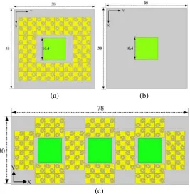
A wideband RCS reduction and gain enhancement for patch antenna can be achieved by using the proposed EBG structure. As shown in Fig. 4, EBGs are placed around series of antenna units and 1×3 antenna arrays to evaluate its effect of RCS and radiation performance.
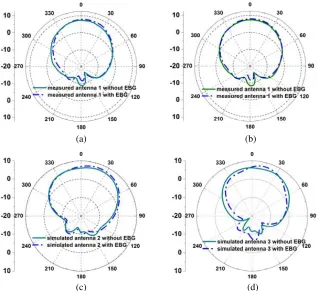
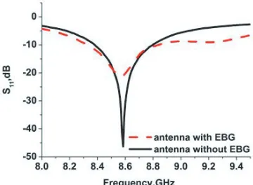
Three patch antennas work at 8.6 GHz (antenna 1), 12.5 GHz (antenna 2) and 16.5 GHz (antenna 3) are designed, respectively. Antenna 1 is fabricated and measured, and a photograph of antenna 1 is shown in Fig. 5. The measured gains of antenna 1 with/without EBG are 7.9 dB and 7.1 dB, respectively. The radiation patterns of three antennas are plotted in Fig. 6. The improvement of the antenna gain demonstrates the effect of the EBG structure. Fig. 7 plots the measuredS-parameter of antenna 1, and it can be seen that the bandwidth of the antenna is slightly widened.
It should be noted that the distance between the EBG and the antenna needs to be carefully selected. This is because when the distance is very small, the mutual coupling seriously affects the radiation performance of the antenna. Therefore, by reasonable choice of this distance, the gain of antenna is improved.
Figure 8 shows the monostatic RCS of antenna unit and antenna array irradiated by TE-polarized and TM-polarized incident waves in normal direction (parameters of antenna 1 are adapted). It can be obviously seen that RCSs of both antenna array and antenna unit are reduced significantly from 9 GHz to 21 GHz. For the antenna unit, three poles of RCS reduction appear at 10 GHz, 14 GHz and 18.5 GHz, and the maximum reduction of RCS is up to 20 dB at higher frequency. The RCS of antenna array is also noticeably reduced, and the maximum of RCS reduction is about 10 dB. Compared with the band-gap frequency of EBG unit, the pole frequency of RCS reduction increases about 2 GHz. This is mainly because of the finite number of EBG unit cells. This problem can be easily solved by carefully controlling the turns of spiral inductance on the EBG surface.
Figure 7. MeasuredS-parameter of antenna 1 with/without EBG.
(a) (b)
4. CONCLUSION
A triple-band electromagnetic band-gap structure used for gain enhancement and wideband RCS reduction of antenna is presented in this paper. The equivalent model is shown to clearly understand the formation of triple bands. Two antennas are fabricated and measured to demonstrate the performance of proposed EBG structure. Gain of antenna is enhanced, and RCS of antenna is significantly reduced in the frequency range from 9 GHz to 21 GHz. Compared with other methods for RCS reduction, this method can realize wideband RCS reduction without sacrificing the radiation performance of antenna. Results show that the method has great potential in the application of wideband RCS reduction.
ACKNOWLEDGMENT
This work is supported by the National Natural Science Foundation of China under Grant Nos. 61274092 and 61674117, and the State Key Program of National Natural Science Foundation of China under Grant Nos. 61434006 and 61334002.
REFERENCES
1. Knott, E. F., J. F. Shaeffer, and M. T. Tuley, Radar Cross Section, SciTech, Raleigh, NC, USA, 2004.
2. Lv, J., S.-X. Gong, and F.-W. Wang, “RCS reduction of Quasi-Yagi antenna,” Progress In Electromagnetics Research C, Vol 53, 89–97, 2014.
3. Ramkumar, M. A., C. Sudhendra, and K. Rao, “A novel low RCS microstrip antenna array using thin and wideband radar absorbing structure based on embedded passives resistors,” Progress In Electromagnetics Research C, Vol. 68, 153–161, 2016.
4. Li, Y. and Y. Liu, “Microstrip antenna using ground-cut slots for low RCS with size miniaturization techniques,” Progress In Electromagnetics Research Letter, Vol. 1, 2008, 211–220.
5. Jiang, W., “Low RCS microstrip antenna array with incident wave in grazing angle,” Progress In Electromagnetics Research C, Vol. 55, 73–82, 2014.
6. Jia, Y., Y. Liu, and S. X. Gong, “Printed UWB end-fire Vivaldi antenna with low RCS,”Progress In Electromagnetics Research Letters, Vol. 37, 11–20, 2013.
7. Zheng, J., S.-J. Fang, and Y. Jia, “RCS reduction of patch array antenna by complementary split-ring resonators structure,”Progress In Electromagnetics Research C, Vol. 51, 95–101, 2014. 8. Liu, T., et al., “RCS reduction of waveguide slot antenna with metamaterial absorber,” IEEE
Trans. Antennas Propag., Vol. 61, No. 3, 479–484, 2013.
9. Volakis, J. L., et al., “Broadband RCS reduction of rectangular patch by using distributed loading,”
Electron. Lett., Vol. 28, No. 25, 2322–2323, 1992.
10. Zhang, J., et al., “RCS reduction of patch array antenna by electromagnetic band-gap structure,”
IEEE Antennas Wireless Propag. Lett., Vol. 11, 1048–1501, 2012.
11. Li, Y. Q., et al., “RCS reduction of ridged waveguide slot antenna array using EBG radar absorbing material,”IEEE Antennas Wireless Propag. Lett., Vol. 7, 473–476, 2008.
12. Xu, W. W., et al., “A novel microstrip antenna with composite patch structure for reduction of in-band RCS,” IEEE Antennas Wireless Propag. Lett., Vol. 14, 139–142, 2015.
13. Soliman, et al., “Optimized design of a low-RCS patch antenna using a frequency selective surface,”
Antennas Propagation Society International Symposium, 329–332, 2012.
14. Liu, Y., et al., “Low RCS microstrip patch antenna using frequency selective surface and microstrip resonator,” IEEE Antennas Wireless Propag. Lett., Vol. 14, 1290–1293, 2015.
15. Liu, Y., et al., “RCS reduction of patch array antenna based on microstrip resonator,” IEEE Antennas Wireless Propag. Lett., Vol. 14, 4–7, 2015.