Enhanced Radio Tomographic Imaging Method for Device-Free
Localization Using a Gradual-Changing Weight Model
Wei Ke1, 2, *, Haoran Zuo1, Mengling Chen1, and Yanli Wang1
Abstract—Radio tomographic imaging (RTI) is a main method in device-free localization (DFL) that can locate a target by analyzing its shadowing effect on wireless links, while removing the requirement of equipping the target with a device. The accuracy of RTI method closely depends on the accuracy of shadowing weight model, which represents the relationship between the shadowing effect of the target on wireless links and target location. However, most existing models have not been accurate enough for many applications since they cannot explain some phenomena observed in DFL practices. To overcome the shortcoming of the existing weight model, this paper proposes a gradual-changing weight model to enhance the imaging quality of RTI. Meanwhile, a foreground target detection algorithm based on the shape feature of the target image is proposed to reduce the negative impact of background noises and pseudo-targets, thereby further enhancing the localization accuracy. The indoor and outdoor experimental results highlight the advantages of using the proposed method in improving the imaging quality and the positioning accuracy.
1. INTRODUCTION
The availability of high-accuracy location awareness in outdoor and indoor environments is a key enabler for a wide range of pervasive wireless applications. Recently, an emerging received signal strength (RSS)-based device-free localization (DFL) [1, 2] technology has attracted much attention. In the DFL system based on radiofrequency (RF) signal, radio transmitters (RTs) and radio receivers (RXs) are used as sensors to sense a target, and the location of the target can be estimated by fusing the changes of RSS measurements of wireless links. In contrast to traditional localization techniques that the tracked entities are required to carry radio devices such as radio frequency identification (RFID) tag, DFL can localize the target without attaching any electronic device and does not require the target to cooperate with the localization system. In some applications, such as battlefield surveillance, emergency rescue, and security safeguard, it is impractical to require a target to carry a cooperative device. Under the situations that traditional localization systems do not work, RSS-based DFL can still infer the target’s location by measuring the target’s effect on the RSS of the network’s links and becomes an effective method for passive localization.
So far, there are two widely used approaches to perform DFL: fingerprint-based method [3–5] and model-based method [6–15]. Fingerprint-based methods need to obtain a pre-trained database of training data labeled with a target’s position in the offline stage. During the online stage, the current RSS measurements are compared to those in the database to estimate the current target’s position. The fingerprint-based method can well describe the relationship between link measurements and target location, but the training process is time consuming. Moreover, this time consuming process needs to
Received 16 April 2019, Accepted 5 June 2019, Scheduled 18 June 2019 * Corresponding author: Wei Ke ([email protected]).
1 Jiangsu Key Laboratory on Opto-Electronic Technology, School of Physics and Technology, Nanjing Normal University, Nanjing
be repeated once the environment is changed. Another significant approach of DFL is to model the RSS variation, due to the shadowing or reflection of the target, as a function of the target’s position. Unlike the fingerprint-based method, model-based approaches use a semi-empirical spatial weight model for the changes in RSS with respect to the locations of the sensors and a target. Inspired by the computed tomography method in medical systems, Wilson and Patwari [6] firstly introduced shadowing-based radio tomography imaging (RTI) method for model-based DFL that can estimate the RSS changes in the RF propagation field of a monitored area using RF sensor networks and then form an image of the changed field by using the regularized method. This image is then used to infer the positions of targets within the deployed network. The performance of the shadowing-based RTI is further improved by the subsequent studies on variance-based RTI [7], histogram-based RTI [8], channel diversity RTI [9, 10], fade-level RTI [11], directional RTI [12], or compressive sensing (CS) methods [13–15]. The benefits of the RTI approach are its intuitive expression through images and high computational efficiency. However, due to the dynamic and sensitive nature of RSS and the mismatch between the a priori model and the actual RSS changes, there are usually lots of noise points or false targets in the RTI image, which may result in large localization errors.
This paper focuses on RTI approaches, and we present an enhanced RTI (ERTI) method to improve the imaging quality of RTI using the gradual-changing weight elliptical model (GEM). Meanwhile, a foreground target detection (FTD) algorithm based on the circular neighborhood model is used to extract the target’ image in order to reduce the negative impact of background noise points and pseudo-targets. The remainder of the paper is organized as follows. Section 2 describes the basic principle of RTI and problem formulation. The details of the gradual-changing weight elliptical model are addressed in Section 3. The target detection algorithm is described in Section 4. The experimental setup and experimental results are given in Section 5. Finally, Section 6 concludes the paper.
2. THE BASIC PRINCIPLE OF RTI AND PROBLEM FORMULATION
Assuming that L wireless nodes are arranged around the localization area, which can make up
M = (L−1)L wireless links. The two-dimensional localization space is evenly divided into N grids, and these grids can be called pixels in RTI. Then, the original RTI work in [6] has been proposed to use a linear model that relates the image to RSS variations:
y=Wx+n (1)
where y = [y1, . . ., yM] is a M ×1 vector that represents the target-affected RSS changes on M links
compared with the RSS measurements when the deployment area is vacant. x = [x1, . . ., xN]T is a
N×1 vector to be estimated, wherexj(1≤j≤N) represents the RSS attenuation at the gridj which corresponds to the fact that whether a target affects thejth grid. TheM×1 vectornrepresents noises.
W is aM×N weight matrix. For the often-used elliptical model (EM) in [6], the weight of pixelj on linkiis
wij = √1
di
1, ifdij1+dij2 < di+β
0, otherwise (2)
where dij1 and dij2 are the distances from the center of pixel j to the two nodes of link i; di is the
distance between two nodes of link i; and β is a tunable parameter defining the width of the ellipse. Since the above problem is an ill-posed inverse problem when M < N, regularization techniques such as Tikhonov regularization [6] and regularized least squares estimators [9] have been used to handle the ill-posedness. Here, we use the Tikhonov regularization approach, which is given as:
x=WTW+αQTQ−1WTy=Ay (3) where Q is the Tikhonov matrix, andα is the regularization parameter. The linear transformation A
can be calculated beforehand enabling real-time image reconstruction.
the influence of link length on weight and ignores the distance relationship between the target and links. More importantly, the elliptical weight model assumes that all the weights in an ellipse are the same, but this is also not consistent with the real target influence that may be different at the different positions in an ellipse. To handle these drawbacks of the elliptical model, Hamilton et al. [16] proposed a novel inverse area elliptical model (IAEM), which defines that the shadowing effect of a target on a wireless link is inversely proportional to the size of the smallest ellipse that contains the target. As a more effective model, exponential-Rayleigh (ER) model [17] is successfully used to capture the shadow fading effect from the line-of-sight (LOS) path to non-line-of-sight (NLOS) area and predict the enhancement phenomenon due to target-induced multipath interferences. However, the ER model fails to take the diffraction fading into account. Different from the ER model, the diffraction-based model [18] exploits the proximity to TX/RX nodes to parameterize the RSS variations, but it ignores the NLOS fading. Recently, based on extensive experiments, the saddle surface model (SaS) [19] is proposed to model the RSS variations in terms of both target-induced multipath interferences and the proximity to TX/RX nodes. Although the above models in [17–19] are more reasonable than the traditional elliptical weight model, they only provide a specific amount of RSS change rather than give a simple weight, which cannot be directly used in existing RTI methods. Coincidentally, these models are all incorporated into the particle filter framework to realize DFL.
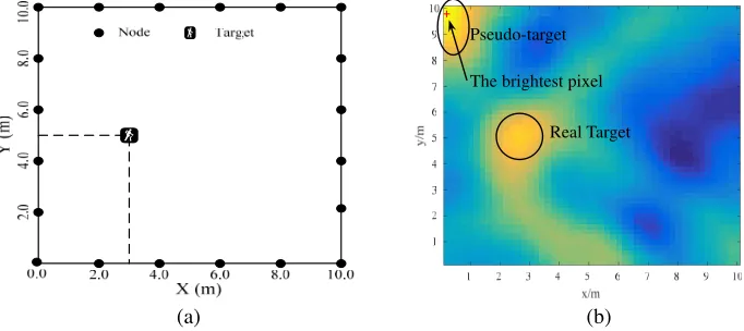
In addition, although the above models significantly enrich the research of the model-based RTI, most models that are obtained empirically or constructed according to the diffraction theory only describe the shadowing effect under the ideal conditions. Due to the dynamic and sensitive nature of RSS, a slight variation of the environment will cause the changes of RSS measurements. Hence, noise points are often unavoidable for RTI results due to the model mismatch. Even some spots that represent pseudo-targets include the brighter pixels appearing on the image as shown in Fig. 1(b) (the detailed experimental setup will be introduced in Section 5). Since the RTI method usually chooses the brightest pixel to represent the target position, the pseudo-target spot may bring large localization error once one pseudo-target is regarded as the real target. Therefore, how to reduce background noise points and pseudo-target spots has become one hot issue of RTI research in recent years.
(a) (b)
Real Target Pseudo-target
The brightest pixel
Figure 1. (a) Geometry of the target position. (b) The illustration of a pseudo-target example.
In view of the above problems, this paper firstly proposes a gradual-changed elliptical weight model to achieve a more accurate description about the relationship between the RSS change and the target influence. At the same time, a foreground target detection algorithm is used to extract the target’ image in order to mitigate the negative impact of background noises and pseudo-targets.
3. GRADUAL-CHANGING WEIGHT MODEL AND MODEL ASSESSMENT
Third, the existing elliptical weight model only considers the influence of link length on weight while ignoring the distance relationship between the target and links.
In fact, many experiments have demonstrated that the weight of pixels in different areas inside an ellipse should be different [16–19]. For example, the target’s influence on the link when a person stands near the LOS path is greater than that when a person is far from the LOS path. Similarly, when a person stands on a LOS path, the influence on the link is greater than when a person stands on an NLOS path inside the same weighting area. In addition, when the distance between a person and nodes is smaller, the influence of the target is greater. Hence, the existing elliptical weight model that uses the unchanged weight in an ellipse is usually unreasonable for real applications.
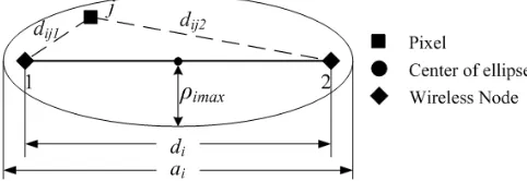
Based on the above analysis, we propose a gradual-changed weight elliptical model which is mathematically described in Eq. (4), and the geometry of the GEM is illustrated in Fig. 2.
wij = ⎧ ⎨ ⎩
ai−(dij1+dij2)
ai−di ×
(dij1−dij2)2
d2i ifdji1+dji2 < dj+ρimax
0 else
(4)
where ai is the length of elliptical major axis on link i, and ρimax =
√
λdi/2 is the maximum first Fresnel radius [20, 21]. In this model, (dij1−dij2)2/d2i represents the weight variation along theith link
direction, while (ai−(dij1+dij2))/(ai−di) describes the weight variation along the vertical direction
of link i.
The main differences between the GEM and traditional elliptical weight model are twofold. Firstly, according to the diffraction theory in [20, 21], most target-affected electromagnetics energy is spread in the first Fresnel zone, while the influence of the target is very small when the target is outside the first Fresnel zone. Different from the existing elliptical model with the unchanged minor axis length, therefore, in our model the minor axis length of each ellipse is equal to the largest first-Fresnel radius, which is related to the link length. Second, the weight inside the ellipse region is not fixed any more. On the contrary, the weight changes according to the position that a target stands.
Figure 2. Geometry of the gradual-changed elliptical weight model.
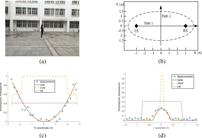
To evaluate the performance of our model, we perform some experiments that use a similar method to that [18, 19] to validate the model and compare its performance with other elliptical models, i.e., traditional EM [6], and IAEM [16] under the same experimental environment. In the experiment, the nodes are put on top of tripods with a height of 1 m from the ground. Two nodes are placed 6 m apart, and the whole experimental scenario is half-space limited by a ground. The transceiver of the wireless nodes is turned to work on 2.45 GHz. All the nodes are equipped with omnidirectional whip antennas with gain of 3 dB. In our experiments, one node transmits a packet to another node while a person stands at each test position along two special trajectories that are designed as illustrated in Fig. 3(b), and the RSS of the link is recorded simultaneously. In order to facilitate comparisons, the RSS change values are normalized to [0, 1].
(a) (b)
(c) (d)
Normalized Attenuation
Normalized Attenuation
Figure 3. (a) Photograph of the experiment scenario. (b) Illustration of the experimental setup. (c) RSS variations along the path 1. (d) RSS variations along the path 2.
are presented as straight lines or segmental straight lines, which means that the weights are same at different locations. Obviously, these models are not satisfied with the experimental measurements and cannot effectively overcome the mismatch between the weight model and real measurements. Further, the unreasonable weight relationship will reduce the imaging quality of RTI and even result in some pseudo-target spots appearing on the image.
4. FOREGROUND TARGET DETECTION ALGORITHM
To more accurately represent the relationship between the weight model and the RSS attenuations caused by the target, a modified elliptical weight model has been proposed and verified by experiments. However, this model is still constructed according to the extensive experimental data and the diffraction theory under normal conditions. Since RSS is sensitive to environmental variations in practice, not only RSS measurements are time varying, but also a slight variation of the environment may possibly cause the mismatch between the weight model and the changes of RSS measurements. Therefore, some pseudo-target spots and background noise points can still appear on the image, even if the modified elliptical weight model is used. Once these pseudo-targets are mistakenly regarded as true targets, the localization error will significantly increase. Hence, this paper proposes a foreground target detection algorithm based on the shape feature of the real target image to further reduce the negative effect of pseudotargets and background noises. This algorithm includes a two-step procedure.
In the first step, we divide all pixels into two categories, i.e., the foreground target pixels and background pixels, by a simple fixed threshold depending on the average brightness value of all pixels. This step is based on the fact that the brightness values of those pixels that represent the target are usually larger than the background noise points’ brightness. Hence, it is reasonable to regard the pixels whose brightness values below the average brightness value as the background pixels and set their brightness values to 0 for eliminating their effects.
in the second step, we exploit the target’s shape information to help finding the real target position. Since human target can be modeled as a cylinder with radius r, which is frequently employed in the literature [17–19], the target-affected area in the RTI image is an approximate circle with almost the same brightness in a 2-D plane. It means that there are a group of high brightness pixels clustered around the target position. On the contrary, the shapes and sizes of spots caused by pseudotargets and noise points are usually random. Moreover, some zero-value pixels may appear in these pseudotarget spots because the brightness values of pseudotarget pixels are not uniform, and some low bright pixels are reset to zero by the first-step threshold operation.
Based on the above analysis, we propose to use the circular neighborhood model to obtain the foreground target. Since the target spot is made of a group of high brightness pixels, the pixel inside this spot will obtain a non-zero brightness value when using the product of all brightness values of pixels in its circular neighborhood to represent its new brightness value. Contrarily, the pixel in the pseudotarget spot will obtain a zero-value brightness if using the same multiplying operation, since there are usually some zero-value pixels in the pseudotarget spot after the first-step threshold operation. Thus, we can remove the most pseudotarget’s pixels and preserve the real target’s pixels via sliding the circular neighborhood model. The circular neighborhood model can be described as:
x(i, j) =x(m, n), x(m, n)−x(i, j)2< r (5)
where x(i, j) and x(m, n) represent the brightness values of the pixel points at (i, j) and (m, n), respectively. r is a user-defined parameter indicating the radius of the circular neighborhood, as shown in Fig. 4. represents the multiple multiplication operation.
Figure 4. The illustration of the circular neighborhood model.
5. EXPERIMENTAL RESULTS
5.1. Physical Description of the Experiment
(a) (b)
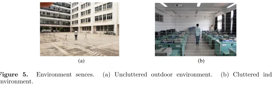
Figure 5. Environment sences. (a) Uncluttered outdoor environment. (b) Cluttered indoor environment.
not, they wait for the next node to transmit. If one node does not transmit, or the packet is corrupted, a timeout causes each receiver to move to the next node in the schedule so that cycle is not halted. To obtain the baseline RSS, measurements are taken for 60 s while the single human target is outside the deployment area. In both scenes, a base-station node listens to all broadcasts from the perimeter nodes and logs the RSS information to a mobile computer with 3.5 GHz processor and 8 GB memory for real-time processing.
To evaluate the performance of the ERTI method, we compare it with the traditional RTI algorithm under different weight models. The default parameters for RTI are as follows: the number of pixels is 2500, and regularization parameter is 4.5. The width of the ellipse for EM and IAEM models is 0.3 m. All the statistical results are the average of 100 repeated experiments with independent measurement data for high confidence.
5.2. Performance Evaluation and Comparison
5.2.1. Localization Performance in the Uncluttered Outdoor Environment (Scene 1)
First, we carried out the RTI experiments in the uncluttered outdoor experimental environment where twenty wireless nodes were placed 2.0 m apart at the perimeter of a 10 m×10 m square area being free from obstructions. A photograph of the experimental setup is shown in Fig. 5(a). In each experimental environment, ten people with different heights and body shapes acted as our targets, and each target was tested at randomly selecting positions under this scene.
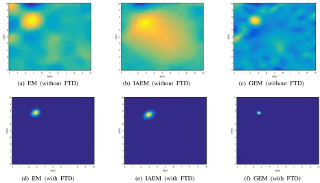
To help the readers to intuitively compare the imaging performance under the different models, Fig. 6 provides an imaging example when the target is located at (3 m, 7.5 m). From Fig. 6(c), we can observe that even if the FTD technique is not used to enhance the localization performance, the target image is basically clear in the GEM-based RTI result. The background noises in Fig. 6(a) are not very bad under the uncluttered outdoor environment, but there is a bright spot on the upper-left corner that is easily regarded as a pseudotarget image. In addition, although there is not an obvious pseudotarget image, the IAEM-based imaging result has a very large target region in Fig. 6(b), which may result in large localization error. However, since few barriers exist in the uncluttered outdoor environment, the imaging results of EM and IAEM models are similar to the GEM-based RTI result after using the FTD technique. These results show that the proposed FTD algorithm can effectively improve the imaging quality and achieve better localization performance.
(a) EM (without FTD) (b) IAEM (without FTD) (c) GEM (without FTD)
(d) EM (with FTD) (e) IAEM (with FTD) (f) GEM (with FTD)
Figure 6. Imaging examples of three models in the uncluttered outdoor environment.
Table 1. Comparisons of localization errors in the uncluttered outdoor environment.
Model Mean (m) STD (m) Median (m)
RTI RTI+FTD RTI RTI+FTD RTI RTI+FTD
EM 0.77 0.30 0.71 0.16 0.51 0.22
IAEM 0.56 0.26 0.49 0.13 0.39 0.19
GEM 0.29 0.21 0.15 0.10 0.23 0.18
localization error of the GEM model is already small before using the FTD technique, the improvement is not very obvious.
5.2.2. Localization Performance in the Cluttered Indoor Environment (Scene 2)
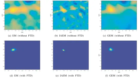
To evaluate the performance of the proposed method in rich multipath scenarios, the experiments were also conducted in a cluttered indoor environment inside a laboratory where twenty wireless nodes were placed 1.0 m apart at the perimeter of a 5 m × 5 m square area. A photograph of the experimental setup is shown in Fig. 5(b), and there are numerous obstructions such as tables and other equipment. All other settings are similar to those in scene 1.
(a) EM (without FTD) (b) IAEM (without FTD) (c) GEM (without FTD)
(d) EM (with FTD) (e) IAEM (with FTD) (f) GEM (with FTD)
Figure 7. Imaging examples of three models in the cluttered indoor environment.
Table 2. Comparisons of localization errors in the cluttered indoor environment.
Model Mean (m) STD (m) Median (m)
RTI RTI+FTD RTI RTI+FTD RTI RTI+FTD
EM 0.88 0.49 0.69 0.29 0.78 0.40
IAEM 0.70 0.36 0.61 0.23 0.59 0.32
GEM 0.50 0.27 0.51 0.19 0.38 0.26
in Figs. 7(d), (e), (f) after using the FTD technique. Thus, the mean values of the localization errors under three models are all less than 0.50 m, and STDs are reduced to less than 0.30 m. These results demonstrate that the FTD technique can not only enhance the localization accuracy, but also improve the localization stability in cluttered environments.
6. CONCLUSION
In order to enhance RTI localization performance, we have proposed a novel gradual-changing weight elliptical model to describe the relationship between link measurement and target location. Compared with existing elliptical models, the GEM can provide more accurate weight information at every possible location within each ellipse area. Meanwhile, a foreground target detection algorithm based on the circular neighborhood model is proposed to further reduce the impact of background noises and pseudo-targets and enhance the localization accuracy. The effectiveness of the proposed scheme has been validated by extensive experiments in both indoor and outdoor environments.
ACKNOWLEDGMENT
REFERENCES
1. Patwari, N. and J. Wilson, “RF sensor networks for device-free localization: Measurements, models, and algorithms,” Proc. of the IEEE Vol. 98, No. 11, 1961–1973, 2010.
2. Shukri, S. and L. M. Kamarudin, “Device free localization technology for human detection and counting with RF sensor networks: A review,” J. Netw. and Computer Appli., Vol. 97, No. 1, 157–174, 2017.
3. Saeed, A., A. Kosba, and M. Youssef, “Ichnaea: A low-overhead robust WLAN device-free passive localization system,” IEEE J. Sel. Topics Signal Process., Vol. 8, No. 1, 5–15, 2014.
4. Sabek, I., M. Youssef, and A. V. Vasilakos, “ACE: An accurate and efficient multi-entity device-Free WLAN localization system,” IEEE Trans. Mob. Comput., Vol. 14, No. 2, 261–273, 2015.
5. Mager, B., P. Lundrigan, and N. Patwari, “Fingerprint-based device-free localization performance in changing environments,” IEEE J. Sel. Areas Commun., Vol. 33, No. 11, 2429–2438, 2015. 6. Wilson, J. and N. Patwari, “Radio tomographic imaging with wireless networks,” IEEE Trans.
Mob. Comput., Vol. 9, No. 5, 621–632, 2010.
7. Zhao, Y. and N. Patwari, “Robust estimators for variance-based device-free localization and tracking,”IEEE Trans. Mob. Comput., Vol. 14, No. 10, 2116–2129, 2015.
8. Zhao, Y. and N. Patwari, “Histogram distance-based radio tomographic localization,” Proc. 11th Int. Conf. IPSN, 129–130, 2012.
9. Kaltiokallio, O., M. Bocca, and N. Patwari, “Enhancing the accuracy of radio tomographic imaging using channel diversity,” Proc. 9th IEEE Int. Conf. MASS, 254–262, 2012.
10. Ke, W., Y. Yuan, X. Zhang, and J. Shao, “Device-free electromagnetic passive localization with frequency diversity,” Progress In Electromagnetics Research M, Vol. 47, 129–139, 2016.
11. Wilson, J. and N. Patwari, “A fade-level skew-laplace signal strength model for device-free localization with wireless networks,” IEEE Trans. Mob. Comput., Vol. 11, No. 6, 947–958, 2012 12. Bocca, M., A. Luong, N. Patwari, and T. Schmid, “Dial it in: Rotating RF sensors to enhance
radio tomography,” arXiv, 2013. [Online]. Available: http://arxiv.org/abs/1312.5480.
13. Ke, W. and T. T. Wang, “Enhanced CS-based device-free localization with RF sensor networks,” IEEE Commun. Lett., Vol. 22, No. 12, 2503–2506, 2018.
14. Wang, J., Q. Gao, X. Zhang, and H. Wang, “Device-free localization with wireless networks based on compressing sensing,”IET Commun., Vol. 6, No. 15, 2395–2403, 2012.
15. Kanso, M. A. and M. G. Rabbat, “Compressed RF tomography for wireless sensor networks: Centralized and decentralized approaches,”Proc. 5th DCOSS, 173–186, 2009.
16. Hamilton, B. R., X. L. Ma, R. J. Baxley, and S. M. Matechik, “Propagation modeling for radio frequency tomography in wireless networks,” IEEE J. Sel. Topics Signal Process, Vol. 8, No. 1, 43–54, 2014.
17. Guo, Y., K. Huang, N. Jiang, X. Guo, and G. Wang, “An exponential-Rayleigh model for RSS-based device-free localization and tracking,”IEEE Trans. Mob. Comput., Vol. 14, No. 3, 484–494, 2015.
18. Wang, Z. H., H. Liu, S. X. Xu, X. Y. Bu, and J. P. An, “A diffraction measurement model and particle filter tracking method for RSS-based DFL,”IEEE J. Sel. Areas Commun., Vol. 33, No. 11, 2391–2403, 2015.
19. Wang, J., Q. H. Gao, M. Pan, X. Zhang, Y. Yu, and H. Y. Wang, “Toward accurate device-free wireless localization with a saddle surface model,” IEEE Trans. Veh. Technol., Vol. 65, No. 8, 6665–6677, 2016.
20. Rappaport, T. S., Wireless Communication: Principles and Practice, Prentice-Hall, Englewood Cliffs, NJ, 1999.