Available online: https://edupediapublications.org/journals/index.php/IJR/ P a g e | 2131
A Modified Partial Product Generator for Redundant Binary
Multipliers
Dr.Ch.Ravi Kumar & M.Venkata Vindhya
1 Prof & HOD 2 M.Tech scholar
Department of ECE Department of ECE Prakasam Engineering College Prakasam Engineering College Kandukur (m), Prakasam(dt),A.P,India. Kandukur (m), Prakasam(dt),A.P,India
[email protected] [email protected]
Abstract
—Due to its high modularity and
carry-free addition, a redundant binary (RB) representation can be used when designing high performance multipliers. The conventional RB multiplier requires an additional RB partial product (RBPP) row, because an error-correcting word (ECW) is generated by both the radix-4 Modified Booth encoding (MBE) and the RB encoding. This incurs in an additional RBPP accumulation stage for the MBE multiplier. In this paper, a new RB modified partial product generator (RBMPPG) is proposed; it removes the extra ECW and hence, it saves one RBPP accumulation stage. Therefore, the proposed RBMPPG generates fewer partial product rows than a conventional RB MBE multiplier. Simulation results show that the proposed RBMPPG based designs significantly improve the area and power consumption when the word length of each operand in the multiplier is at least 32 bits; these reductions over previous NB multiplier designs incur in a modest delay increase (approximately 5 percent). The power-delay product can be reduced by using the proposed RB multipliers when compared with existing RB multipliers
.
I INTRODUCTION
DIGITAL multipliers are widely used in arithmetic units of microprocessors, multimedia
and digital signal processors. Many algorithms and architectures have been proposed to design high-speed and low-power multipliers .A normal binary (NB) multiplication by digital circuits includes three steps. In the first step, partial products are generated; in the second step, all partial products are added by a partial product reduction tree until two partial product rows remain. In the third step, the two partial product rows are added by a fast carry propagation adder. Two methods have been used to perform the second step for the partial product reduction. A first method uses four-two compressors, while a second method uses redundant binary (RB) numbers. A redundant binary representation (RBR) is a numeral system that uses more bits than needed to represent a single binary digit so that most numbers have several representations. An RBR is unlike usual binary numeral systems, including two's complement, which use a single bit for each digit.
A RB multiplier consists of a RB partial product (RBPP) generator, a RBPP reduction tree and a RB-NB converter. A Radix-4 Booth encoding or a modified Booth encoding (MBE) is usually used in the partial product generator of parallel multipliers to reduce the number of partial product rows by half.
Available online: https://edupediapublications.org/journals/index.php/IJR/ P a g e | 2132 the circuit’s complexity down to a minimum. This
results in lower power operation in an FPGA or CPLD and provides for multiplication when no hard multipliers are otherwise available such as in a Lattice MachXO2 PLD which was used in this example. Booth Recoding makes these advantages possible by skipping clock cycles that add nothing new in the way of product terms. The Radix-4 Booth Recoding is simply a multiplexor that selects the correct shift-and-add operation based on the groupings of bits found in the product register.
II EXISTING SYSTEM
Review of booth encoding and RB partial
product generator
Radix-4 Booth Encoding
Booth encoding has been proposed to facilitate the multiplication of two’s complement binary numbers. It was revised as modified Booth encoding or radix-4 Booth encoding. The MBE scheme is summarized in Table 1, where A ¼ aN1aN2 . . . a2 a1a0 stands for the multiplicand, and B ¼ bN1bN2 . . . b2 b1b0 stands for the multiplier. The multiplier bits are grouped in sets of three adjacent bits. The two side bits are overlapped with neighboring groups except the first multiplier bits group in which it is {b1, b0, 0}. Each group is decoded by selecting the partial product shown in Table 1, where 2A indicates twice the multiplicand, which can be obtained by left shifting. Negation operation is achieved by inverting each bit of A and adding ‘1’ (defined as correction bit) to the LSB
Methods have been proposed to solve the problem of correction bits for NB radix-4 Booth encoding (NBBE-2) multipliers. However, this problem has not been solved for RB MBE multipliers.
Fig.1. Conventional RBPP architecture for an 8-bit MBE multiplier.
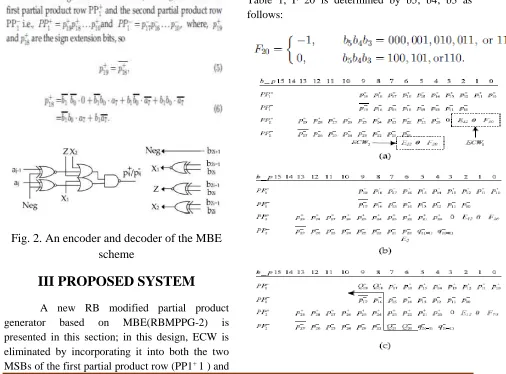
Available online: https://edupediapublications.org/journals/index.php/IJR/ P a g e | 2133 where i represents the ith row of the RBPPs, Ei2 ∑
f0; 1g and Fi0 ∑ 0;_1 f g. In Fi0, a _1 correction term is always required by RB coding. If Fi0 also corrects the errors from the MBE recoding, then the correction term cancels out to 0. That is to say that if the multiplicand digit is inverted and added to 1, then Fi0 is 0, otherwise Fi0 is _1. The error-correcting digit Ei2 is determined only by the Booth encoding:
Fig. 2. An encoder and decoder of the MBE
scheme
III PROPOSED SYSTEM
A new RB modified partial product generator based on MBE(RBMPPG-2) is presented in this section; in this design, ECW is eliminated by incorporating it into both the two MSBs of the first partial product row (PP1+ 1 ) and
the two LSBs of the last partialproduct row (PP- n/4 Proposed RBMPPG_2 Fig. 3 illustrates the proposed RBMPPG-2 scheme for an 8_8-bit multiplier. It is differentfrom the scheme in Fig.1, where all theerror-correcting terms are in the last row. ECW1 is generated byPP1 and expressed as
The ECW2 generated by PP2 (also defined as an extra ECW) is left as the last row and it is expressed as:
Available online: https://edupediapublications.org/journals/index.php/IJR/ P a g e | 2134 Fig. 3 . (a) The first new RBMPPG-2 architecture
for an 8-bit MBE multiplier; (b) the further revised RBMPPG-2 architecture by replacing E22 and F20 with E2, q_ 2ð_2Þ , and q_ 2ð_1Þ ; (c) the final
proposed RBMPPG-2 architecture by totally eliminating ECW2 and further combing E2 into
Qþ 19, Qþ 18, Q_ 21, and Q_ 20.
A modified radix_4 Booth encoding and a decoding circuit for the partial product PP2 are proposed here (Fig. 4); an extra three input OR gate is then added to the design of [10] (Fig. 2.2)
Fig. 4. The modified radix-4 Booth encoding and decoding scheme for PPþ2
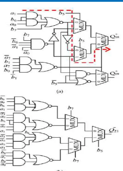
The delay of the RBMPPG-2 can be further reduced by generating Qþ19+, Q 18+, Q 21-, Q20- directly from the multiplicand A and the multiplier B. The relationships between pþ 19, pþ 18 and A, B
. Fig.5. The circuit diagram of the modified partial product variables: (a) Qþ 18 and Qþ
19, (b) Q_ 21.
Design of RBMPPG-2-Based
High-Speed RB Multipliers
The proposed RBMPPG-2 can be applied to any 2n-bit RB multipliers with a reduction of a RBPP accumulation stage compared with conventional designs. Although the delay of RMPPG-2 increases by one-stage of TG delay, the delay of one RBPP accumulation stage is significantly larger than a one-stage TG delay. Therefore, the delay of the entire multiplier is reduced. The improved complexity, delay and power consumption are very attractive for
the proposed design.
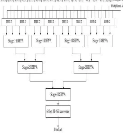
A 32-bit RB MBE multiplier using the proposed RBPP generator is shown in Fig.6. The multiplier consists of the proposed
Available online: https://edupediapublications.org/journals/index.php/IJR/ P a g e | 2135 up by the RBPP reduction tree that has three
RBPP accumulation stages. Each RBPP accumulation block contains RB full adders (RBFAs) and half adders (RBHAs). The 64-bit RB-NB converter converts the final accumulation results into the NB representation, which uses a hybrid parallel-prefix/carry select adder (as one of the most efficient fast parallel adder designs).
There are four stages in a conventional 32-bit RB MBE multiplier architecture; however, by using the proposed RBMPPG-2, the number of RBPP accumulation stages is reduced from 4 to 3 (i.e., a 25 percent reduction).
Fig. 6. The block diagram of a 32-bit RB multiplier using the proposed RBMPPG-2.
IV RESULTS
SIMULATION RESULTS:
DESIGN SUMMARY:
RTL SCHEMATIC:
Available online: https://edupediapublications.org/journals/index.php/IJR/ P a g e | 2136
TECHNOLOGY SCHEMATIC:
V CONCLUSION
A new modified RBPP generator has been proposed in this paper; this design eliminates the additional ECW that is introduced by previous designs. Therefore, a RBPP accumulation stage is saved due to the elimination of ECW. The new RB partial product generation technique can be applied to any 2n-bit RB multipliers to reduce the number of RBPP rows from N=4 þ 1 to N=4. Simulation results have shown that the performance of RB MBE multipliers using the proposed RBMPPG-2 is improved significantly in
terms of delay and area. The proposed designs achieve significant reductions in area and power consumption when the word length is at least 32 bits. The PDP can be reduced by up to 59 percent using the proposed RB multipliers when compared with existing RB multipliers. Hence, the proposed RBPP generation method is a very useful technique when designing area and PDP efficient power-of-two RB MBE multipliers.
REFERENCES
[1] A. Avizienis, “Signed-digit number representations for fast parallel arithmetic,” IRE Trans. Electron. Comput., vol. EC-10, pp. 389– 400, 1961.
[2] N. Takagi, H. Yasuura, and S. Yajima, “High-speed VLSI multiplication algorithm with a redundant binary addition tree,” IEEE Trans. Comput., vol. C-34, no. 9, pp. 789–796, Sep. 1985.
[3] Y. Harata, Y. Nakamura, H. Nagase, M. Takigawa, and N. Takagi, “A high speed multiplier using a redundant binary adder tree,” IEEE J. Solid-State Circuits, vol. SC-22, no. 1, pp. 28–34, Feb. 1987.
[4] H. Edamatsu, T. Taniguchi, T. Nishiyama, and S. Kuninobu, “A 33 MFLOPS floating point processor using redundant binary representation,” in Proc. IEEE Int. Solid-State Circuits Conf., 1988, pp. 152–153.
[5] H. Makino, Y. Nakase, and H. Shinohara, “A 8.8-ns 54x54-bit multiplier using new redundant binary architecture,” in Proc. Int. Conf. Comput. Des., 1993, pp. 202–205.
[6] H. Makino, Y. Nakase, H. Suzuki, H.
8.8-Available online: https://edupediapublications.org/journals/index.php/IJR/ P a g e | 2137 ns 54 54-bit
multiplier with high speed redundant binary architecture,” IEEE J. Solid-State Circuits, vol. 31, no. 6, pp. 773–783, Jun. 1996.
[7] Y. Kim, B. Song, J. Grosspietsch, and S.
Gillig, “A carry-free
54b 54b multiplier using equivalent bit conversion algorithm,” IEEE J. Solid-State Circuits, vol. 36, no. 10, pp. 1538– 1545, Oct. 2001.
[8] Y. He and C. Chang, “A power-delay efficient hybrid carry-lookahead carry-select based redundant binary to two’s complement converter,” IEEE Trans. Circuits Syst. I, Reg. Papers, vol. 55, no. 1, pp. 336–346, Feb. 2008.
[9] G. Wang and M. Tull, “A new redundant binary number to 2’s-complement number converter,” in Proc. Region 5 Conf.: Annu. Tech. Leadership Workshop, 2004, pp. 141–143.
[10] W. Yeh and C. Jen, “High-speed booth encoded parallel multiplier design,” IEEE Trans. Comput., vol. 49, no. 7, pp. 692–701, Jul. 2000.