Intelligent Control System for Microgrids Using Multiagent
System by Matlab
Garrepally Santhosh Chary, Daravastu Srinivas, P. Nageswara Rao,
M.Tech, Dept. of EEE, Vidya Jyothi Institute of Technology (Autonomous), Hyderabad, India
Associate professor, Dept. of EEE, Vidya Jyothi Institute of Technology (Autonomous), Hyderabad,
India
Associate professor, Dept. of EEE, Vidya Jyothi Institute of Technology (Autonomous),
Hyderabad,India
ABSTRACT-This paper displays a savvy control of a microgrid in both grid-associated and islanded modes utilizing the multi specialist system (MAS) strategy. This shrewd control comprises of three levels. The primary level is based on nearby hang control, the second level repays power adjust between the supply and the request ideally, and the third level is at the system level based on power advertise. A clever MAS was created and actualized based on establishment for savvy physical specialists models by speaking to each major self-governing component in the microgrid as an astute programming operator. The operators interact with each other for settling on their own choices locally and ideally. The coordination among the operators guarantees power quality, voltage, and frequency of the microgrid by deciding the set points that upgrade the general operation of the microgrid. The proposed control design and techniques for the continuous control of microgrids were examined in detail, and tried under different load conditions and diverse network configurations. The results of the examinations show the practicality of the proposed control and procedures, and also the capacity of the MAS system for the operation of microgrids.
Index Terms— Grid-connected operation,
information and communications technology-enabled architecture, intelligent control, islanded operation microgrid, multi agent system (MAS).
I. INTRODUCTION
More than twenty years of research in the field of agents and multi-agent systems have offered remarkable results from both theoretical and practical point of view. However, after so many years of the research there is no general consensus on some basic notions such as “what is an agent?”, “what is a multi-agent systems”, agreement on the terminology used, etc. Indeed, this fact makes confused those interested in applying agent based or multi-agent based technology to solve practical problems. This short
note is intended to serve as a “gentle” introduction to the field of agents and multi-agent systems particularly for those interested in using these technologies in solving practical engineering problems. The main purpose of the note is to familiarize readers with basic terminology and definitions. This note will not enumerate (many) and elaborate different views on the subject but rather presents a view on the subject that (according to authors of the note) may help engineering people to get feeling on this important subject. Throughout of this note, when deemed necessary, simple examples are provided to illustrate different concepts. All the examples are based on the idea to use agent or multi-agent technology to design effective load shedding scheme. For readers interested for a deeper inside in the subject, from different points of view, this note offers at the end a list of useful references and links.
more problematic then in the case of agents what makes any attempt to present MAS a hard problem.
A MAS is independent if each individual agent pursues its own goals independently of the others. A MAS is discrete if it is independent, and if the goals of the agents bear no relation to one another. Discrete MAS involve no cooperation. However agents can cooperate with no intention of doing so and if this is the case then the cooperation is emergent. The term deliberative in Figure 4 is not to be mixed with the term of deliberative agent, and in the figure it refers to the idea that agents jointly plan their actions so as to cooperate with each other. The cooperation within a MAS can be realized in three ways: • by explicit design (the designer of the agents purposely designs the agent behaviors so that cooperation occurs), • by adaptation (individual agents learn to cooperate), • by evolution (individual agents cooperation evolves through some kind of evolutionary process.
Main advantages of MAS are robustness and scalability. Robustness refers to the ability that if control and responsibilities are sufficiently shared among agents within MAS, the system can tolerate failures of one or more agents. Scalability of MAS originates from its modularity. It should be easier to add new agents to a MAS than to add new capabilities to a monolithic system.
These exploration works demonstrate the capability of this distributed computational astute method for the future power system operation. In this paper, a canny MAS design for the control and administration of a microgrid is proposed. Logenthiran et al. have introduced MAS for a constant operation of a microgrid through a continuous computerized test system, yet it mainly focuses just on the ongoing power administration.
This paper manages a continuous control of microgrid from a power electronics point of view, and the execution issues are talked about in detail. Astute control ideas used to guarantee stable constant operation are likewise introduced. In the test system, generators and FCs are equipped for creating controlled active power on request. Subsequently, they are utilized to control voltage and frequency amid islanded operation. Conversely, PV system isn't a dispatchable source since its output power mainly
relies upon climatic conditions. Along these lines, it is ideally utilized as a supplementary source amid the operational method of the microgrid. Moreover, a power-sharing strategy was created for dispatching distributed generators (DGs) in the microgrid.
To successfully control distributed resources inside a microgrid, distributed and helpful control engineering is encouraged inside the MAS innovation. Control techniques were created by speaking to each significant component in the microgrid as a self-governing insightful operator, which can speak with different specialists to settle on its own choices. The MAS was executed in Java Agent Development Entity (JADE) [28], which is an open source establishment for keen physical specialist (FIPA) [29] grievance multi operator stage. The microgrid was displayed in MATLAB.
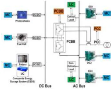
Fig. 1: Configuration of a hybrid microgrid
An ongoing correspondence interface between the MAS and the microgrid was actualized. The remaining paper is organized as takes after. Segment II clarifies a microgrid configuration and its main components. Segment III proposes an ICT-empowered control design. Area IV introduces the execution of the MAS. Segment V depicts the execution of distributed control procedures. Area VI exhibits the viability of the proposed control for operation of a hybrid microgrid. At long last, the conclusions are given in Section VII.
II. CONFIGURATION OF A MICROGRID
demonstrates a schematic configuration of a hybrid microgrid, which was displayed in MATLAB. Microgrid has a few distributed energy resources and every asset has their own attributes. They are controlled by isolated micro source controllers (MCs)/specialists. On the off chance that there are diverse sorts of energy resources with various attributes and the vast majority of them require some level of autonomy basic leadership, at that point multiagent displaying of the resources is most reasonable approach. Having numerous interacting specialists could accelerate a system's operation by giving a strategy to parallel calculation based on the request. On the off chance that control and responsibilities are adequately shared among various specialists, the system can endure disappointments by at least one of the operators. It is simpler to include operators in MAS. Thus, parallelism, robustness, and adaptability are the key advantages of MASs.
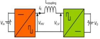
Fig. 2: DAB bidirectional dc–dc converter
A. Micro sources:
The microgrid comprises of a few distributed energy resources, for example, PV system, FC, and DGs. They are associated by means of appropriate power electronic interfaces. PV system creates power from solar radiation that fluctuates with time. FC works under steady-state conditions. The accessible models of PV and FC [30] were utilized as a part of the microgrid displaying. All these distributed energy resources have their own MCs. With a specific end goal to develop the experiment, genuine insolation and temperature information for PV were utilized. DGs take an interest in a power advertise that is controlled by the secondary level control. For the situation contemplate, three DGs working with diesel,
biodiesel, and flammable gas were incorporated. Their power outputs are controlled based on their fuel costs.
B. Composite Energy Storage:
System Energy storage is critical in a renewable powered microgrid because of the intermittent idea of renewable energy sources and persistent varieties in load-side request [31]. Composite energy storage system (CESS) comprises of a high energy thickness storage component, for example, battery to meet the requests of intermittent nature of renewable energy sources, for example, PV systems and high power thickness storage component like ultra capacitor to meet brisk variances of load requests. In this paper, a battery bank and a ultra capacitor-based CESS is used to smooth out power vacillations in the renewable energy generation, in this manner enhancing the unwavering quality and productivity of microgrids. The dc bus voltage of microgrid is settled and controlled by CESS.
A constant CESS show was utilized to display the microgrid. The power interface of CESS is accomplished through the dual-active-bridge (DAB) converter as appeared in Fig. 2 and its streamlined identical circuit is appeared in Fig. 3. Any number of parallel DAB branches can be utilized to meet the necessities of CESS. Power exchange is accomplished by phase moving the voltage over the primary and secondary sides of the high-frequency transformer.
The normal output current of the DAB converter is given by
Where, I0 is the output current on the secondary side, d is controlled phase move, Vin is the info voltage on the primary side, L is the coupling inductance, Ts is switching time, and n is the turns ratio of transformer.
The normal output power of the DAB converter is
communicated as
Where, Pin is input power on the primary side, P0 is output power on the secondary side, η is change productivity, and V0 is secondary side terminal voltage. Lumped model of energy storages in CESS is described by energy limit, power evaluations, and maximum incline rate of power.
The state-of-charge (SOC) of CESS is computed based on current integration, which is the place Pin is input power on the primary side, P0 is output power on the secondary side, η is transformation productivity, and V0 is secondary side terminal voltage. Lumped model of energy storages in CESS is described by energy limit, power evaluations, and maximum slope rate of power. The state-of-charge (SOC) of CESS is computed based on current integration, which is
Where, Q is evaluated limit and iES is present drawn from energy storage.
C. Power Electronic:
Interfaces Power electronic interfaces are fundamental to associate any kind of distributed energy asset to the microgrid. With the improvement of solid-state-based bundles and advances in circuit topologies, power electronic devices can change over any type of electrical energy to a more alluring and usable frame. An essential favorable position of power electronics is its to a great degree quick reaction time. Power electronic interfaces can react to power quality issues inside a sub cycle extend. To expand output power of PV, the PV system is associated through a maximum power point tracking (MPPT) system that has a dc/dc converter with a straightforward control plot for all conditions. In view of the low output voltage of FC, dc/dc converter of FC steps up the voltage to the dc bus voltage of 800 V.
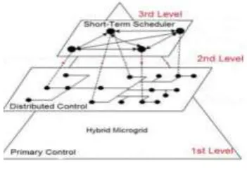
Fig. 4: Three-level control architecture for microgrids
A bidirectional dc– dc converter is required to interface the CESS to the dc bus for controlling the dc bus voltage and the power flow. Touch converter is a promising configuration for bidirectional power exchange and this can be accomplished by phase moving primary and secondary side bridge voltages. The isolation between the energy storage and the load is satisfied by a high frequency transformer. High-frequency transformer determinations are output power is 70 kVA, input voltage is 220 V with an output voltage of 800 V, and working frequency of 20 kHz. An interleaved current-bolstered full-bridge converter and a DAB converter are chosen for FC and CESS. A power converter building block (PCBB) is kept in the system to encourage the functions of dc/air conditioning bus inverter, active filter, and grid-associated inverter.
III. PROPOSED CONTROL ARCHITECTURE
Smart grid, a future power system, searches for fully decentralized control design however it can't be changed all of a sudden from unified to decentralized control engineering. It ought to be changed gradually. Presently, analysts propose some new in part decentralized control structures for various sorts of power systems and do contextual investigations to approve them. Different control and administration structures have been proposed in the writing for microgrid control.
introduces all control levels from the base level to the best level.
A. First-Level Control:
The base level control fuses nearby controllers (LCs) for microgrid components. They can react rapidly. The LCs controls the resources with no correspondences. Controllers react based on nearby estimations and system dynamics to guarantee power adjust amongst supply and load. These controllers give instantaneous power adjust when frequency deviation happens. The primary level control is composed utilizing a representative control system, which controls the adjustment in frequency or speed of generators when any occurrence happens.
The senator control system changes the outputs of generators that are required to take an interest in this control by setting the hang esteems as indicated by determinations. A hang circle is incorporated as a piece of the speed senator, with the goal that the system load is shared among different generators. The system requires the following level of control (i.e., the second-level control) to repay any power confound. The time casing of this primary reaction is in seconds.
B. Second-Level Control:
The second-level control is utilized for remunerating power irregularity between the power supply and the load ideally. The second-level control is likewise in charge of control activities when a microgrid frequency deviation happens. It computes the measure of power expected to convey the system to the reference frequency, and offers that power among the resources ideally. This control system is based on ongoing estimations, and the control technique considers every one of the sources.
The new generation set points are delivered by adding the ascertained power amendment to the at first doled out power. In this paper, these are done by the relating individual specialists. The power settings of micro sources are indicated at first as per the calendar from the third level control. The second-level control additionally does synchronizing function of the microgrid and the main grid for encouraging the change between islanded mode and grid-associated mode. This control works slower than the main level control. It gives a reaction at time intervals of 5 min.
C. Third-Level Control:
The third-level control is at the highest point of the control design, and actualized with a fleeting scheduler (i.e., day-ahead organizer) whose essential functionalities incorporate generation planning, request side administration, showcase investment, load anticipating, discount energy value determining, and renewable energy guaging [36]. This control performs supply– request coordinating in 30-min intervals as discount showcase cost shifts in 30-min intervals.
The relating specialists in the MAS for the third-level control have diverse kinds of generation booking calculations and techniques based on the rules and strategies connected in the microgrid. So as to do the operation of the microgrid, the second level and the third level of the control systems facilitate with each other. This control conspire fundamentally expands the power generation output of neighborhood DGs, and improves power trades between the microgrid and the main power grid.
IV. IMPLEMENTATION OF MULTIAGENT SYSTEM
The microgrid considered in this paper comprises of a few self-governing basic leadership entities, for example, PV operator, FC specialist, CESS specialist, PCBB operator, DG specialists, load specialists, and CB specialists (i.e., circuit breakers). Every operator in the MAS speaks to a noteworthy self-governing component of the microgrid. The operators can screen and control the comparing components, and they can speak with different specialists. No focal control operator is accessible in the proposed MAS. Each source or load settles on choices locally. This can conceivably make a distributed, versatile, and robust control for the microgrid.
directory facilitator (DF) benefit, which is like business repository.
DF enables operators to enroll their administrations, and inquiry the DF to discover what administrations are offered by different specialists, or which specialists offer certain administrations. JADE gives philosophy bolster, and furthermore gives office to create client characterized metaphysics. This means it is conceivable to characterize claim vocabulary and semantics by client for the substance of the messages traded among the operators. To actualize a MAS control system, it is important to characterize the functions of every specialist as per the qualities and objectives of them. Targets and responsibilities of every operator in the MAS are talked about in the following Section.
A.Agents Specification
In this step, details of specialists in the MAS are characterized.
1) Power-Source Agent: It is in charge of checking, controlling, and arranging power delivered by the relating microsource and its ON/OFF status.
2) Load Agent: It is equipped for observing, controlling, and arranging power level of controllable load and its association status. It is fit for shedding off based on the accessible power, particularly when microgrid is in islanded mode. The MAS has isolate load specialists for critical load (CL) operator and non-CL (NCL) operator.
3) CESS Agent: It screens its SOC level and demands power from microsource operators and power grid specialist when the SOC level is low based on the nearby estimated data. Nearby control of CESS decides how much energy is expected to store or supply at each moment.
4) PCC Agent: It screens the grid voltage, phase edge, and frequency, and is in charge of illuminating the adjustments in the microgrid status to different specialists.
5) PCBB Agent: It screens voltage, current, and power level of the microgrid. Grid operator gives current and voltage reference set points to PCBB specialist for choosing whether it needs to draw or supply power from or to the main grid.
6) Grid Agent: It is in charge of checking and arranging power from the microsources and sending out or bringing in power when the microgrid is in a gridconnected mode. Power fare or import to or from
the main grid is as indicated by the market operation actualized by the third-level control.
7) CB Agent: It interacts with the comparing breaker in the microgrid, and is equipped for filling in as a switch. The circuit breaker operator can prompt interface or disengage of a generator or load based on control summons.
8) Bus Agent: It screens voltage greatness and phase edge, and maintains the voltage that does not surpass its points of confinement. The proposed engineering has isolate dc and air conditioning bus specialists.
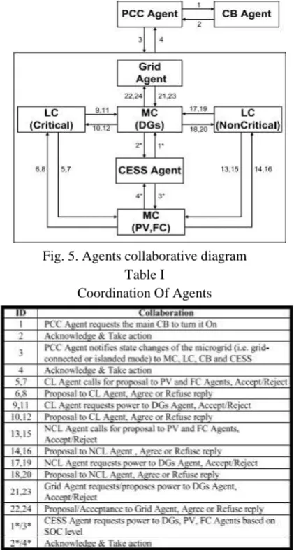
Fig. 5. Agents collaborative diagram Table I
Coordination Of Agents
B. Agent Roles and Responsibilities.
This segment gives the characterized functions and parts of every specialist based on the proposed control engineering. The function of a specialist is characterized by an arrangement of practices. A few practices can be executed by a specialist. Subsequently, every operator has independence to play out its objective arranged practices. The collective diagram of the MAS is appeared in Fig. 5.
Fig. 6. Rules behind the negotiation among agents. This represents the interaction among operators, and their interaction with nature. Table I gives a general thought regarding how these specialists are characterized, and demonstrates the required messages for the interactions. The MAS is instated by enlisting the specialists in DF related with comparing administrations.
In this manner, when a specialist needs to make an impression on another operator, the specialist requests that from DF give a rundown of specialists to the asked for benefit. For instance, a load specialist will search for the source operators in DF at whatever point it needs power. After the instatement, every one of the specialists will begin playing out their functions. The operators consult among themselves to share the accessible energy. All exchanges among the specialists are begun by load operators. The load operators ask for alternate specialists for a proposition of power supplies. In the event that an appropriate proposition is accessible in the system, they acknowledge the proposition.
Power source operators (i.e., PV, FC, and DGs) get power ask for from the load specialists, and send a proposition of accessible power that can be given to the load specialists at the time of demand. Operators begin consulting among themselves, and take choices based without anyone else rules. The regular choices are which power sources to acknowledge, and what measure of power to give by the acknowledged power sources. The logic behind the operator correspondence is appeared in Fig. 6. Characterizing a proper philosophy that indicates the message substance of an operator dialect is a vital piece of MAS plan. Metaphysics gives an approach to share regular comprehension of data among operators.
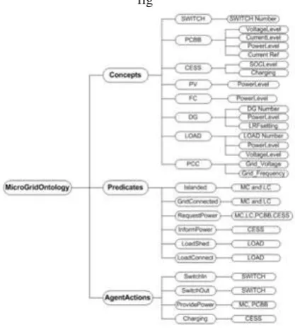
Operators convey by exchanging messages, and the metaphysics is utilized to structure the messages. Ordinarily, the substance of the message consents to the substance dialect and metaphysics. In this paper, Ontology for the specialists (i.e., Micro Grid Ontology) has been created for constant control of microgrids. This is appeared in Fig. 7.
C. Control System Interface
The MAS for the constant control of a hybrid microgrid was produced and executed in JADE stage. The MAS and the microgrid show have been interfaced with the end goal that it gives an ongoing correspondence channel to trade messages between them.
fig
As indicated by the proposed three-level control system, the third-level control does here and now booking by showcase operation, which gives planning of producing units in 30-min intervals. Be that as it may, the measure of load and microsources creation differs constantly with time. Sometimes these change from the estimated esteems as well.
In this way, a constant control is required for the operation of microgrid, which must give new set points to controllable power sources and loads persistently by adjusting generation and utilization continuously. This ongoing control can be actualized as a brought together or a distributed system. A distributed control approach for low-voltage power distribution networks possibly offers points of interest over an incorporated approach in: 1) unwavering quality; 2) adaptability and transparency; and 3) correspondence effectiveness.
The distinction amongst brought together and distributed control approaches is characterized by parts and responsibilities taken by the entities in the system. In a brought together control approach, micro sources and loads take after the guidelines of microgrid focal controller, while in a distributed control approach, self-sufficiency for micro sources and loads are furnished with dif ferent goals and possessions. In this manner, the distributed control approach is appropriate for dealing with numerous sources and loads in the power distribution system. As indicated by the distributed approach, the main obligation is given to the LCs, MCs for sources, and LCs for loads. MCs contend to amplify the generation of the relating sources keeping in mind the end goal to fulfill the request progressively, and LCs do sheltered and smooth operation of the comparing controllable loads. The sorts of power sources considered in the paper are quickly clarified as takes after.
1) Controllable Power Sources: Most of the DGs working by powers are sufficiently quick to reset the power outputs. Consequently, they can take part in load-frequency con trol. CESS likewise can take an interest by changing its power generation level as indicated by system conditions.
2) Fixed Power Source: Due to the attributes of FC, it is alluring to work with a constant output power. In
this paper, FC is considered as a settled power source.
3) Main Grid: The MAS guarantees the power trade between the microgrid and the main grid. Regardless of whether the power is sent out to the main grid or imported from the main grid is chosen by the third-level control.
4) Non-controllable Power: PV panel is a non-controllable power source in the microgrid, which is worked together with MPPT idea in both grid-associated and islanded modes.
A. Grid-Connected Microgrid
In a grid-associated mode, the main part of the microgrid is to suit: 1) genuine or reactive power produced by the microsources and 2) load request. Amid the grid-associated mode, the frequency of the system is maintained by the main grid. The MAS enhances the genuine power outputs of the sources. The main criteria for choosing power sharing among microsources are minimization of operational cost of the sources.
B. Islanded Microgrid
Amid upstream blackout conditions, the microgrid is intended to detach itself from the main grid utilizing a shrewd switch. The switch consequently recognizes any unsettling influences like faults inside or outside the microgrid by watching frequency and phase edges at the association points. Reconnection is worthy if voltage blunder is <3%, frequency mistake is <0.1 Hz, and phase point blunder is <10°. In islanded mode, there is no help from the main grid. Voltage and frequency control, and additionally genuine and reactive power adjust ought to be given by the microgrid itself. Because of the non controllable idea of PV, micro sources, for example, DGs, FC, and CESS, are in charge of guaranteeing the power adjust by means of retaining and infusing the power contrast between the generation and the neighborhood load request. In the event that accessible generation isn't adequate to secure every one of the loads, the least critical loads (i.e., NCLs) will be shed.
C. Control Algorithm and Power Sharing Scheme
power settings of the micro grid resources. The execution sequence is depicted as takes after. 1) Each load operator approaches the power-source specialists for a proposition of power supply. 2) Power-source operators acknowledge the demand, and send a proposition as indicated by the accessible power.
3) Collecting every one of the proposition and choosing which powe sources to acknowledge and at what measure of power.
4) Load specialist sends power demand to power-source operator based on the individual load prerequisites.
5) Power-source specialist acknowledges the demand, and give the administration by asking for current power level of each source and figuring power alterations of each source as needs be. 6) Power-source specialist sends new power set points to each source. CL specialist, NCL operator, grid specialist, and CESS specialist will likewise ask for the required power from the power-source specialist. The power booking technique of power-source specialist with various DGs is given as takes after.
7) Calculate the power distinction (∆PiDGT ) between the generation and the load request where ∆CL Pi is changes in power of the ∆_Pi^Grid is changes in power of the is changes in power to the grid, ∆_Pi^CESS is changes in power to the CESS, ∆_Pi^DGn is changes in power from nth DG, I is the time step, and N is number of DGs in the microgrid.
8) Calculate the required power alteration for each source, which is corresponding to their accessible maximum generation capacities
Where ∆_PiDGn is the deliberate power output of nth DG, ∆_Pi^(DGn-m)is the maximum power point of confinement of nth DG, and SRPDGn I is the required power change for nth DG. The system has variable energy source, for example, PVs, and thus it is interesting to demonstrate the active power control of the hybrid microgrid system continuously.
Active power is considered for every one of the loads and generators for clarification reason, be that as it may, if the microgrid is associated with the grid both active and reactive power control is fundamental for constant situations. The required power modifications are computed for each source, and new power set points will be allocated likewise.
VI. SIMULATION RESULTS
The proposed approach was utilized for the continuous control of a 500-kW hybrid microgrid. The microgrid contains the accompanying distributed sources: a 150-kW PV system, a 60-kW FC, a 65-kW CESS, three synchronous generators whose evaluations are 175, 75, and 250 kW, a CL of 375-kW top, and a NCL of 125-375-kW top. The system works at an appraised frequency of 50 Hz. The dc bus voltage is 800 V and air conditioning bus line to line voltage is 400 V.
The test system structure for the CASE ponder is the same as the hybrid microgrid configuration exhibited in Fig. 1. Simulation examines were completed on ongoing control of the microgrid. Keeping in mind the end goal to make the simulations reasonable, recorded information of solar light and temperature have been utilized by the PV demonstrate. Further, load request information are sustained into the test system by gathering genuine information from a local location. The power settings of microsource are at first set by the day-ahead calendar by the third-level control. The three-contextual analyses were done for showing the proposed approach and control techniques. Segments III-A– III-C depict these in detail.
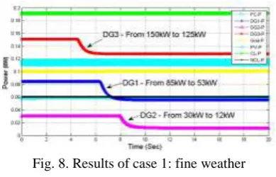
A. Case 1: Fine Weather Condition (13–13:15 h)
Fig. 8 demonstrates the results of this contextual investigation. It can be seen from the figure that when the request is low and the power outputs of the sources are expected to lessen from their underlying qualities to work the microgrid financially
Fig. 8. Results of case 1: fine weather
B. Case 2: Clouded Weather Condition (13:00– 13:15 h)
Second investigation was led on one more day. A 15-min interval was done investigations on obfuscated climate condition. For this situation, PV system delivers little power output at 13:00 h since the climate is overcast. At time = 13:00 h, CESS produces power for the setback before the operators (i.e., controllers) make a move on it. Fig. 9 demonstrates the output powers of DGs. The output powers of DGs are changed from beginning qualities to new qualities as operators require getting more power from all DGs.
Fig. 9. Results of case 2: clouded weather
.
Fig. 10.Variations of grid current and DG currents
Fig. 11. Preplanned islanding and primary control actions
C. Case 3: Islanded Mode Operation (18:00–18:15 h)
Third investigation was led on a run of the mill day. A 15-min interval was done examinations islanded mode operation of the microgrid. Microgrid has a nearby load request of 400 kW (i.e., 300 kW of CL and 100 kW of NCL), and a neighborhood generation of 335 kW (i.e., PV = 5 kW, FC = 60 kW, DG1 = 115 kW, DG2 = 45 kW, and DG3 = 110 kW). The system draws 65-kW power from the main grid. At time 18:00 h, a preplanned fault was made at the upstream. In this way, the microgrid is disengaged from the upstream and worked in islanded mode. Figs. 10 and 11 demonstrate the control activities performed in the system for a preplanned islanding. It can be observed that strength of the microgrid isn't lost because of primary control activity of the sources.
Permissible voltage variety is 5% and suitable frequency variety is 1% under steady state. Amid transients, for example, load shedding/islanded mode, a 3% variety in frequency is considered. With a specific end goal to reestablish the system frequency to its reference esteem, the MAS organizes for the measure of power required to be encouraged back what's more, discover the method for sharing power among the sources in the system.
VII. CONCLUSION
This paper introduced a MAS approach for the clever control and administration of a microgrid. The distributed constant control system is proposed with hang based LCs and some deliberative controllers. The proposed control system is actualized on MAS. Insights about the multi specialist design and the advancement of the MAS were depicted in this paper. Further, insights about demonstrating of microgrid and its components are depicted in this paper. The operators deal with the comparing energy sources and loads as indicated by their individual destinations and objectives. The MAS gives a two-way correspondence divert for all components in the microgrid. This correspondence channel is utilized for helpful, focused, also, transaction forms among the entities for the continuous control of the system. To exhibit the adequacy of the proposed multi operator based control system, some contextual investigations were completed on a hybrid microgrid. Results of the thinks about demonstrate the proposed approach can give fruitful execution to the continuous control of microgrids.
REFERENCES
[1] R. H. Lasseteret al., “Integration of distributed
energy resources: The CERTS microgrid concept,” California Energy Csommission, Sacramento, CA, USA, White Paper P500-03-089F, 2003. [2] N. Hatziargyriou, H. Asano, R. Iravani, and C. Marnay, “Microgrids,”IEEE Power Energy Mag., vol. 5, no. 4, pp. 78–94, Jul./Aug. 2007.
[3] M. Shahidehpour and Y. Wang, Communication and Control in ElectricPower Systems: Applications of Parallel and Distributed Processing. New York, NY, USA: Wiley, 2003.
[4] M. Wooldridge, “Intelligent agents,” in
Multiagent Systems, G. Weiss, Ed. Cambridge, MA, USA: MIT Press, 1999, pp. 3–51.
[5] T. Nagata and H. Sasaki, “A multi-agent approach to power system restoration,” IEEE Trans. Power Syst., vol. 17, no. 2, pp. 457–462, May 2002.
[6] J. M. Solanki, S. Khushalani, and N. N. Schulz, “A multi-agent solution to distribution systems restoration,” IEEE Trans. Power Syst., vol. 22, no. 3, pp. 1026–1034, Aug. 2007.
[7] J. Hossack, S. D. J. McArthur, J. R. McDonald, J. Stokoe, and T. Cumming, “A multi-agent approach to power system disturbance diagnosis,” in Proc. IEEE 5th ICPSMC, Apr. 2002, pp. 317–322.
[8] S. D. J. McArthur, E. M. Davidson, J. A. Hossack, and J. R. McDonald, “Automating power system fault diagnosis through multi-agent system technology,” in Proc. IEEE 37th Annu. Hawaii ICSS, Jan. 2004, pp. 1–8.
[9] H. F. Wang, “Multi-agent co-ordination for the secondary voltage control in power-system contingencies,” IEE Proc.-Generat., Transmiss.,Distrib., vol. 148, no. 1, pp. 61–66, Jan. 2001.
[10] J. M. Solanki and N. N. Schulz, “Multi-agent system for islanded operation of distribution systems,” in Proc. IEEE PES PSCE, Oct./Nov. 2006, pp.
s 1735–1740.
[11] L. R. Phillips, H. E. Link, R. B. Smith, and L. Weiland, “Agent-based control of distributed infrastructure resources,” Sandia Nat. Lab., Albuquerque, NM, USA, Tech. Rep. SAND2005-7937,
2006.
[12] S. Rahman, M. Pipattanasomporns, and Y. Teklu, “Intelligent distributed autonomous power systems (IDAPS),” in Proc. IEEE PES GeneralMeeting, Jun. 2007, pp. 1–8.
[13] T. Logenthiran and D. Srinivasan, “Multi-agent system for the operation of an integrated microgrid,”
J. Renew. Sustain. Energy, vol. 4, no. 1, p. 013116, 2012.
[14] J. Lagorse, D. Paire, and A. Miraoui, “A multi-agent system for energy management of distributed power sources,” Renew. Energy, vol. 35, no. 1, pp. 174–182, 2010.
[15] S. D. J. McArthur et al., “Multi-agent systems
GARREPALLY SANTHOSH CHARY received the bachelor’s degree in electrical and electronics engineering from Jawaharlal Nehru Technological University, Hyderabad, Telangana, India in 2014 & Master’s degree in electrical power systems from Vidya Jyothi Institute of Technology (Autonomous), Hyderabad, India.
DARAVASTU SRINIVAS
received the bachelor’s degree in electrical and electronics engineering from Jawaharlal Nehru Technology University, Hyderabad, India in 2006 & Master’s degree in electrical power engineering from Jawaharlal Nehru Technological University, Hyderabad, India, in 2006.He held various roles as Assistance/Associate Professor in VJIT from 2006 to till date.
P.NAGESWARA RAO is an