3d Model and Program Generation for Gear Train by
Using Cam
P Md Suhail1, S Abzal Basha2, C Lakshmaiah3
1
P.G. Scholar, 2MTECH (CAD/CAM), 3MTECH(Machine design)
1,2,3
BRANCH: CAD/CAM
1,2,3
Geethanjali College Of Engineering & Technology ,Nannur (V),Oravakal (M), Kurnool Email: [email protected], [email protected]
ABSTRACT
The gear is an important component serving as a key player in power transmission mechanisms. The reason that gearing is so important is because the gear is the convenient way to obtain reliable power transmission without slippage. If there is only one gear mounted on each shaft, the gear train is known as simple gear train. that is, each shaft has only one gear. Usually when two gears mate, they rotate opposite to each other. When we use three gears each mounted on separate shaft, the direction of rotation of the last gear will be same as that of the direction of rotation of first gear.
Problem definition of the project is the component has 20 number of teeth and they subjected to contact force in between driver and follower gears. So it needs to specify proper type of material and optimized NC Program for manufacturing to get high surface finish due to presence of teeth. The aim of this project is to create a 3d model of reverted gear train and analyze the those gears for proposing proper material and optimum machining process plan (generating optimized NC program) this gives the high surface finish. To developing design of gear train, NX-CAD shall be used. After that static analyzed by Ansys software. Finally NX-CAM software is used for generating accurate NC program for manufacturing.
INTRODUCTION
1.1 OVERVIEW OF GEAR:
Gearing is one of the most critical
components in a mechanical power
transmission system, and in most industrial rotating machinery. It is possible that gears will predominate as the most effective means of transmitting power in future machines due to their high degree of reliability and compactness. In addition, the rapid shift in the industry from heavy industries such as shipbuilding to industries such as automobile manufacture and office automation tools will necessitate a refined application of gear technology.
1.2 GEAR TRAIN
Gear train is a combination of gears and used for transmitting motion and power from one shaft to another shaft. Gear trains are used to achieve large and different velocity ratio in small area or space. Gear trains are use for increasing or reducing speed of driven shaft. Examples of gear trains use in machines are lathe machine, milling machine, in watch and many others. 1.3 TYPES OF GEAR TRAIN
Simple Gear Train
Compound Gear Train
Riveted Gear train
Epicycle Gear Train 1.4.1 SIMPLE GEAR TRAIN
velocity ratio. Only one gear is mounted on each shaft and these shafts are rigidly fixed or not movable. Simple gear train consist three major area or part and these are driving gear, driven gear and intermediate gears. In which driving gear is mounted on driving shaft and driven gear is mounted on driven shaft and these both gears are mesh with the help of intermediate gears. In simple gear train intermediate gears play major role and intermediate gears will be one or more in simple gear train depending upon design or application. To obtain different velocity ratio different size gears are used. In simple gear trains power and motion transmit from driving gear to intermediate gears and from intermediate gears to driven gears. In this way simple gear trains are work.
Fig.1.1 Simple gear train 1.4.2 COMPOUND GEAR TRAIN
Compound gear train is a type of gear train in which two intermediate gears (gears between driving gear and driven gear) are mounted on one shaft. Means only one gear on driving shaft and driven shaft, and intermediate shafts have two mounted gears. Compound gear trains are use to get large velocity ratio or different speed in a small area or space. Compound gear box is good example of compound gear trains.
Fig.1.2 Compound gear train
1.3 REVERTED GEAR TRAIN
Reverted gear trains are a special type of gear trains. In which driving gear shaft axis and driven gear shaft axis are in a line. In reverted gear train one gear is mounted on each driving and driven shaft and on intermediate shaft two gears are mounted, reverted gear train are arrange in this way that driving gear transmit motion and power to intermediate shaft gear and other gear of intermediate shaft transmit motion and power to driven gear. Reverted gear trains are use there, where velocity ratio required in small space. Watches are good example of reverted gear trains. In watches reverted gear trains are used, in which minute and hour hands of watches are on a same axis.
Fig.1.3 Reverted gear train 1.4.4 EPICYCLIC GEAR TRAIN
epicyclic gear trains, the shaft axes are not fixed means the shaft axis is movable. There is a relative motion between the gears axis. Epicyclic gear trains may consist of simple gear trains, compound gear trains and mixed simple and compound gear trains. The advantage of epicyclic gear train is that, it can get very high or very low velocity ratio compared to simple gear trains and compound gear trains. The common example of epicyclic
gear train is differential gear box of automobile.
Fig.1.4 Epicyclic gear train
These are the type gear trains are use in machine according to require velocity ratio, speed, space and application.
1.4 OBJECTIVES OF PROJECT
The goals of this project is to develop the manufacturing NC program for accurate and analyzed reverted gear train. To developing design of gear train, NX-CAD shall be used. After that static analyzed by Ansys software. Finally NX-CAM software is used for generating accurate NC program for manufacturing.
1.5 INTRODUCTION TO
UNIGRAPHCS
UNIGRAPHICS, developed by
Siemens systems, France, is a completely
re-engineered, next-generation family of CAD/CAM/CAE software solutions for product life cycle management. It is easy to use state of the art user interface and
delivers innovative technologies for
maximum productivity and creativity. It serves the basic design tasks by providing different work benches. A work bench is defined as a specified environment consisting of a set of tools, which allows the user to perform specific design tasks in a particular area. The basic work benches in UNIGRAPHICS are
Part design
Wire frame and surface design Assembly design
Drafting
NX, also known as NX unigraphics or usually just u-g, is an advanced
CAD/CAM/CAE software package
developed by Siemens PLM software. It is used, among other tasks, for:
Design (parametric and direct
solid/surface modelling)
Engineering analysis (static, dynamic, electro-magnetic, thermal, using the finite element method, and fluid using the finite volume method).
Manufacturing finished design by using included machining modules
First release of the new "next generation" version of unigraphics and i-deas, called NX. this will eventually bring the functionality and capabilities of both unigraphics and i-deas together into a single consolidated product.
Increasing complexity of products, development processes and design teams is challenging companies to find new tools and methods to deliver greater innovation and higher quality at lower cost. leading-edge technology from Siemens PLM software delivers greater power for today’s
design challenge. from innovative
synchronous technology that unites
parametric and history-free modeling, to NX active mockup for multi-cad assembly
technology that sets new standards for speed, performance, and ease of use.
NX automates and simplifies design by leveraging the product and process knowledge that companies gain from experience and from industry best practices. it includes tools that designers can use to capture knowledge to automated repetitive tasks. the result is reduced cost and cycle time and improved quality.
Overview of Solid Modeling:
The Unigraphics NX Modelling application provides a solid modeling system to enable rapid conceptual design.
Engineers can incorporate their
requirements and design restrictions by
defining mathematical relationships
between different parts of the design.
Design engineers can quickly
perform conceptual and detailed designs using the Modeling feature and constraint based solid modeller. They can create and edit complex, realistic, solid models interactively, and with far less effort than more traditional wire frame and solid based systems. Feature Based solid modeling and editing capabilities allow designers to change and update solid bodies by directly editing the dimensions of a solid feature and/or by using other geometric editing and construction techniques.
Advantages of Solid Modeling:
Solid Modeling raises the level of expression so that designs can be defined in terms of engineering features, rather than lower-level CAD geometry. Features are parametrically defined for dimension-driven editing based on size and position.
Features:
Powerful built-in engineering-oriented form features-slots, holes, pads, bosses,
pockets-capture design intent and
increase productivity
Patterns of feature instances-rectangular and circular arrays-with displacement of individual features; all features in the
pattern are associated with the master feature.
Blending and Chamfering:
zero radius
Ability to chamfer any edge
Cliff-edge blends for designs that cannot accommodate complete blend radius but still require blends
Advanced Modeling Operations:
Profiles can be swept, extruded or revolved to form solids
Extremely powerful hollow body
command turns solids into thin-walled designs in seconds; inner wall topology will differ from the outer wall, if necessary
Fixed and variable radius blends may overlap surrounding faces and extend to a Tapering for modeling manufactured near-net shape parts
User-defined features for common design elements (Unigraphics NX/User-Defined Features is required to define them in advance
General Operation: Start with a Sketch
Use the Sketcher to freehand a sketch, and dimension an "outline" of Curves. You can then sweep the sketch using Extruded Body or Revolved Body to create a solid or sheet body. You can later refine the sketch to precisely represent the object of interest by editing the dimensions and by creating relationships between geometric objects. Editing a dimension of the sketch not only modifies the geometry of the sketch, but also the body created from the sketch.
Creating and Editing Features:
entering new values. You can create solid bodies of any desired design that can later be defined as a form feature using User Defined Features. This lets you create your own custom library of form features.
Associativity:
Associatively is a term that is used to indicate geometric relationships between individual portions of a model. These relationships are established as the designer uses various functions for model creation. In an associative model, constraints and relationships are captured automatically as the model is developed. For example, in an associative model, a through hole is associated with the faces that the hole penetrates. If the model is later changed so that one or both of those faces moves, the hole updates automatically due to its association with the faces. See Introduction to Feature Modeling for additional details.
Positioning a Feature:
Within Modeling, you can position a
feature relative to the geometry on your model using Positioning Methods, where you position dimensions. The feature is then associated with that geometry and will maintain those associations whenever you edit the model. You can also edit the position of the feature by changing the values of the positioning dimensions.
Reference Features:
You can create reference features,
such as Datum Planes, Datum Axes and
Datum CSYS, which you can use as
reference geometry when needed, or as construction devices for other features. Any feature created using a reference feature is associated to that reference feature and retains that association during edits to the model. You can use a datum plane as a reference plane in constructing sketches, creating features, and positioning features. You can use a datum axis to create datum
planes, to place items concentrically, or to create radial patterns.
Expressions:
The Expressions tool lets you incorporate your requirements and design restrictions by defining mathematical relationships between different parts of the design. For example, you can define the height of a boss as three times its diameter, so that when the diameter changes, the height changes also.
Boolean Operations:
Modeling provides the following Boolean Operations: Unite, Subtract, and Intersect. Unite combines bodies, for example, uniting two rectangular blocks to form a T-shaped solid body. Subtract removes one body from another, for example, removing a cylinder from a block to form a hole. Intersect creates a solid body from material shared by two solid bodies. These operations can also be used with free form features called sheets.
Undo:
You can return a design to a previous state any number of times using the Undo function. You do not have to take a great deal of time making sure each operation is absolutely correct, because a mistake can be easily undone. This freedom to easily change the model lets you cease worrying about getting it wrong, and frees you to explore more possibilities to get it right.
Additional Capabilities:
physical properties from the solid bodies, including mass properties. Shading and hidden line capabilities help you visualize complex assemblies. You can identify interferences automatically, eliminating the need to attempt to do so manually. Hidden edge views can later be generated and placed on drawings. Fully associative dimensioned drawings can be created from solid models using the appropriate options of the Drafting application. If the solid model is edited later, the drawing and dimensions are updated automatically.
Parent/Child Relationships:
If a feature depends on another object for its existence, it is a child or dependent of that object. The object, in turn, is a parent of its child feature. For example, if a HOLLOW (1) is created in a BLOCK (0), the block is the parent and the hollow is its child. A parent can have more than one child, and a child can have more than one parent. A feature that is a child can also be a parent of other features. To see all of the parent-child relationships between the features in your work part, open the Part Navigator.
Creating a Solid Model:
Modeling provides the design
engineer with intuitive and comfortable modeling techniques such as sketching, feature based modeling, and dimension driven editing. An excellent way to begin a design concept is with a sketch. When you use a sketch, a rough idea of the part becomes represented and constrained, based on the fit and function requirements of your design. In this way, your design intent is captured. This ensures that when the design is passed down to the next level of engineering, the basic requirements are not lost when the design is edited.
The strategy you use to create and edit your model to form the desired object depends on the form and complexity of the object. You will likely use several different
methods during a work session. The next several figures illustrate one example of the design process, starting with a sketch and ending with a finished model. First, you can create a sketch "outline" of curves. Then you can sweep or rotate these curves to create a complex portion of your design.
PROBLEM DEFINITION AND
METHODOLOGY
Problem definition of the project is the component has 20 number of teeth and they subjected to contact force in between driver and follower gears. So it needs to specify proper type of material and optimized NC Program for manufacturing to get high surface finish due to presence of teeth. METHODOLOGY
Design of reverted gear train shall be done by NX-CAD
Analysis was done on designed Gear train using Ansys software.
Analysis was done by using low carbon steel.
Contact stress results obtained from analysis results.
Manufacturing of reverted gear train done using
NX-DESIGNING OF REVERTED GEAR
4.1 DESIGN PROCEDURE FOR
REVERTED GEAR:
Fig.4.2 Extrude of above 2Dsketch of Reverted gear
Fig.4.3 2Dsketch of Reverted gear
Fig.4.4 Extrude of above 2Dsketch of Reverted gear
Fig.4.5 Final model of Reverted gear
Fig.4.6 Final model of Reverted gear
STRUTURAL ANALYSIS OF
REVERTED GEAR
5.1 FINITE ELEMENT METHOD
The Basic concept in FEA is that the body or structure may be divided into smaller elements of finite dimensions called “Finite Elements”. The original body or the
structure is then considered as an
assemblage of these elements connected at a finite number of joints called “Nodes” or “Nodal Points”. Simple functions are chosen to approximate the displacements over each finite element. Such assumed functions are called “shape functions”. This will represent the displacement within the element in terms of the displacement at the nodes of the element.
complex problems that can be represented
in differential equations form. The
applications of FEM are limitless as regards the solution of practical design problems.
Due to high cost of computing power of years gone by, FEA has a history of being used to solve complex and cost critical problems. Classical methods alone
usually cannot provide adequate
information to determine the safe working limits of a major civil engineering construction or an automobile or an aircraft. In the recent years, FEA has been universally used to solve structural engineering problems. The departments, which are heavily relied on this technology, are the automotive and aerospace industry. Due to the need to meet the extreme demands for faster, stronger, efficient and lightweight automobiles and aircraft, manufacturers have to rely on this technique to stay competitive.
FEA has been used routinely in high volume production and manufacturing industries for many years, as to get a product design wrong would be detrimental. For example, if a large manufacturer had to recall one model alone due to a hand brake design fault, they would end up having to replace up to few millions of hand brakes. This will cause a heavier loss to the company.
The finite element method is a very important tool for those involved in engineering design; it is now used routinely to solve problems in the following areas.
Structural analysis
Thermal analysis
Vibrations and Dynamics
Buckling analysis
Available Commercial FEM software packages
ANSYS (General purpose, PC and
workstations)
SDRC/I-DEAS (Complete
CAD/CAM/CAE package)
NASTRAN (General purpose FEA on
mainframes)
LS-DYNA 3D (Crash/impact
simulations)
ABAQUS (Nonlinear dynamic
analysis)
NISA (A General purpose FEA tool)
PATRAN (Pre/Post processor)
HYPERMESH (Pre/post processor)
5.2 STATIC ANALYSIS OF
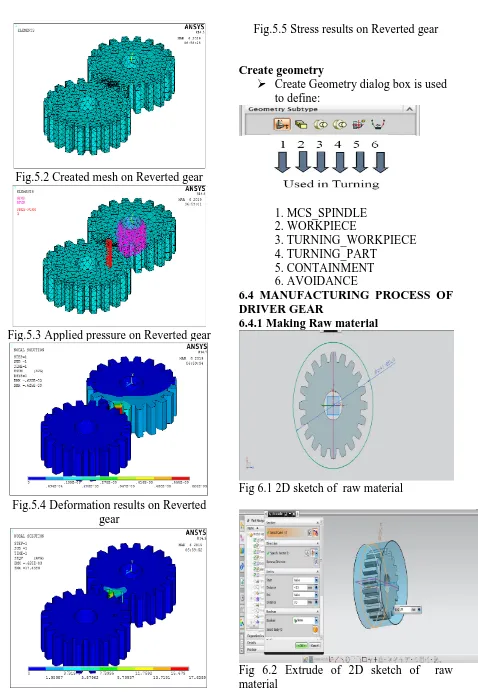
REVERTED GEAR Steel material properties Young’s modulus: 200Ga Poisson ratio :0.3
Density : 8000Kg/m3 Yield strength : 280MPa Loading condition
Contact pressure 3MPa is applied in between contact point of Reverted gear Center hole constrained in all DOF.
Fig.5.1
Fig.5.2 Created mesh on Reverted gear
Fig.5.3 Applied pressure on Reverted gear
Fig.5.4 Deformation results on Reverted gear
Fig.5.5 Stress results on Reverted gear
Create geometry
Create Geometry dialog box is used to define:
1. MCS_SPINDLE 2. WORKPIECE
3. TURNING_WORKPIECE
4. TURNING_PART 5. CONTAINMENT
6. AVOIDANCE
6.4 MANUFACTURING PROCESS OF DRIVER GEAR
6.4.1 Making Raw material
Fig 6.1 2D sketch of raw material
Fig 6.3 Raw material surrounding of gear
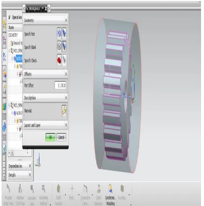
6.4.2 Assigning Machining coordinate system, raw material and part for turning operations
Fig 6.4 Assigning Machining coordinate system
Fig 6.5 Assigning raw material and part
6.4.3 FACE TURNING OPERATION
Fig. 6.6 Generating turning spun
Fig. 6.8 Assigning tool moving points
Fig. 6.9 Assigning Face cutting limits
Fig. 6.10 Assigning depth of cut
Fig.6.11 Facing operation
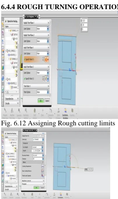
6.4.4 ROUGH TURNING OPERATION
Fig. 6.12 Assigning Rough cutting limits
Fig. 6.13 Assigning depth of cut
Fig.6.15 Assigning Machining coordinate system for Back face operations
6.4.6 FACE TURN OPERATION
Fig.6.16 Facing operation
6.4.5 DRILLING OPERATION
Fig.6.17 Drilling operation
Fig.6.18 Drilling operation 6.4.6 Assigning Machining coordinate system, raw material and part to Milling operations
Fig.6.20 Assigning work piece and part
6.4.7 PLANAR MILLING OPERATION
Fig.6.21 Assigning part boundaries
Fig.6.22 Depth of cut value
Fig.6.23 Planar milling operation
RESULTS AND CONCLUSION
In this project Manufacturing process plan generated for steel reverted gear. Design of reverted gear train completed by NX-CAD software. Ansys software is used for analyzing the gear. NX-CAM software is used for manufacturing process generating for gear.
Finally Accurate NC Program generated for steel reverted gear..
TOOLING LIST TURNING POINTS
CONVERT TO NC CODE
Using the post processor we have to convert CL file data into machine specified NC part program
1. In the Project Manager, select the first operation on the Operations page, then hold down the Shift key and select the last operation. All the cutting
operations are selected.
2. Press the right mouse button and select NC Code from the menu.
3. Select a Machine Format file from the pull down list (3-Axis/5-Axis). 4. Select Apply.
RESULTS
1. 3D model of automobile piston component is done using NX-CAD software.
2. Generated 3D model is drafted and cross checked with 2D inputs for verification. 3. Tool path is generated on 3D model of
automobile piston using NX-CAM software
4. NC program is generated for automobile piston component and this program is
given to 4-axis TURN-MILL CNC machine through DNC line
REFERENCES:
1. J. J. Uicker, G. R. Pennock, and J. E. Shigley, 2003, Theory of Machines and Mechanisms, Oxford University Press, New York.
2. B. Paul, 1979, Kinematics and
Dynamics of Planar Machinery,
Prentice Hall.
3. JJ Coy, DP Townsend, EV Zaretsky,
"Gearing", NASA Reference
Publication 1152, AVSCOM Technical Report 84-C-15, 1985
4. Chad Randl, "Revolving architecture: a history of buildings that rotate, swivel, and pivot".
5. L. Meirovitch: Elements of Vibration Analysis, McGraw-Hill, New York, 1986.
6. John M. Miller (2005-10-26). "Hybrid electric vehicle propulsion system architectures of the e-CVT type". IEEE Transactions on Power Electronics 21 (3): 756– 767.doi:10.1109/TPEL.2006.872372.
7. B. Paul, 1979, Kinematics and
Dynamics of Planar Machinery,
Prentice Hall.
8. J. J. Uicker, G. R. Pennock and J. E. Shigley, 2003, Theory of Machines and Mechanisms, Oxford University Press, New York.
9. P. A. Simionescu (1998-09-01). "A Unified Approach to the Assembly Condition of Epicyclic Gears". ASME Journal of Mechanical Design 120 (3): 448–453. doi:10.1115/1.2829172.
10. Lynwander, P., 1983, Gear Drive Systems: Design and Application. Marcel Dekker, New York