ISSN (Print) : 2320 – 3765 ISSN (Online): 2278 – 8875
I
nternational
J
ournal of
A
dvanced
R
esearch in
E
lectrical,
E
lectronics and
I
nstrumentation
E
ngineering
(An ISO 3297: 2007 Certified Organization)
Vol. 4, Issue 2, February 2015
Implementation of SSSC-Based Cascade
H-Bridge Model using Compensation
Technique
P. Shahanaz Salma1
Assistant Professor, SREC Engineering College, Nandyal, Andhra Pradesh, India1.
ABSTRACT: The SSSC is used to operate the transmission line at stable condition. Various schemes of SSSC is
already proposed. And a still lot of scope is left in this development to make it more efficient in terms of voltage stress, switching losses and harmonic suppression. The scheme proposed here is used to produce a H - bridge based cascaded inverter. It can produce the pulses with different width and magnitude. It almost resembles a sine wave at the output of transformer. The output results are compared with conventional type SSSC with cascaded type. This paper solved only the simulation part of this work. In the proposed work a scale down model of the SSSC can be proposed to build. This scale down model can be used to analysis the different situations like voltage compensation part. The sample of voltage and current will be taken from the transmission line and is given to the processor to decide the firing angle for the thyristor device. A cascaded type H - bridge based multilevel inverter is used as SSSC. Three DC separate sources are used here as energy source for the SSSC. These three DC source can be interfaced with SSSC in a sequential manner as explained in different modes. This sequential switching is helpful in reducing switching losses and switching stresses.
KEYWORDS: Flexible AC Transmission System (FACTS), Cascade H-Bridge, phase imbalance, series
compensation, static synchronous series compensator (SSSC), voltage-sourced converter
I.INTRODUCTION
Static Synchronous Series Compensator (SSSC) is a FACTS device which has its wide range of applications in transmission lines and grids. In power system, several FACTS devices such as STATCOM, static VAR compensator, UPFC , TCSC etc are employed in maintaining power stability and operate the transmission system as reliable one. Based on the performance of these FACTS devices flickering and SSR can also be reduced in transmission grids SSSC based hybrid series compensation scheme combine the capacitor action with TCSC and SSSC are employed in damping of SSR(sub-synchronous resonance). In this hybrid scheme capacitor connected in series with SSSC or TCSC series with capacitor is connected to mitigate the SSR (sub synchronous resonance.
Fig 1. Schematic diagram of series compensator techniques
The main objective of this system is to compensate the active power in transmission line and maintain the voltage to be in phase with line current or at reduced phase angle displacement. Also the power transmission system stability could be maintained and mitigation of flickering. Harmonics presence will also be reduced to remarkable level.
II. SSSC SCHEME
The proposed SSSC based cascaded model is shown in fig 2. To compensate the voltage in transmission line several methods are discussed in recent systems. In all those methods the voltage compensating methodology is different since the injecting voltage to transmission lines are in series to the transmission line. The line current fully depends on the load and load fluctuation. The main concept of this system is to maintain the displacement angle between the line voltage and current should be maintained constant or very closer to the actual value. Transmission line voltage compensation method are mostly employed to maintain the voltage stability and this can be achieved by synchronous condenser, static VAR compensators etc.
The cascade H-bridge technique based STATCOM and DSTATCOM are used in the existing system for voltage balancing. Difference in capacitor voltage may be due to imbalanced charging of capacitors[4]. In the proposed system DC voltage source will be connected in series at various switching sequence depending upon the PWM signals. PWM signals are generated based on the transmission grid voltage. Transmission voltage parameters are sensed by PT(potential transformer) and corresponding signals are given to the controller in which the PWM generation is decided.
ISSN (Print) : 2320 – 3765 ISSN (Online): 2278 – 8875
I
nternational
J
ournal of
A
dvanced
R
esearch in
E
lectrical,
E
lectronics and
I
nstrumentation
E
ngineering
(An ISO 3297: 2007 Certified Organization)
Vol. 4, Issue 2, February 2015
Fig 2. SSSC cascaded Hydrid model
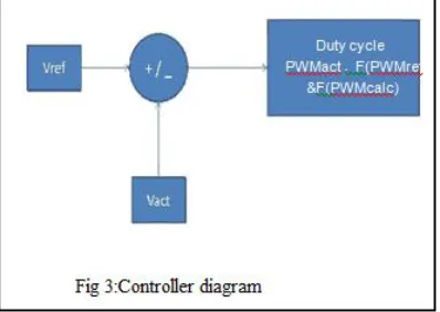
III. VOLTAGE CONTROLLER
In the generation of PWM pulse controller should monitor the transmission line voltage parameters and depending on this parameters the duty cycle is decided. When the transmission voltage deviate from its inphase value the duty cycle varies with respect to the variation in the transmission line parameters. The actual voltage is taken from the transmission line and a reference voltage is set. Comparator combines the reference voltage and actual voltage which results in change of duty cycle.
PWM calc = (Ton/(Ton+Toft))
Unit size is the min. size of the time(ms). If Vact > Vref Ton =Ton - unit size & Toff = Toff + unit size Duty cyle and frring angle will reduce.
Fig 4. Flow chart for controller logic
The flow chart for controller logic is shown in fig.4.describes the calculation algorithm of compensation scheme and duty cycle calculation. In flow chart algorithm different condition of transmission line voltage is referred. The flow chart mentioned in the above fig.4 analysis the grid voltage condition and PWM is calculated by referring the grid voltage and standard reference voltage. Duty cycle is calculated and varied with respect to the actual gird voltage. If the computed voltage is less than the actual voltage then reference voltage is Ton =Ton + unit size. If actual voltage is greater than the reference voltage then Ton =Ton - unit size. If the actual calculated voltage is equal to the reference voltage the system does not performs any and remains ideal.The controller check for the condition often and changes the duty cycle depending on the transmission voltage.
IV. SIMULATION RESULTS
The simulation work for the proposed system is done with help of simulink in MATLAB. The cascade H-bridge circuit is constructed and the MOSFET switches is used. In simulation instead of MOSFET switches are used. In ideal switch its assumed that the switching losses is nil. . In most of the switching devices switching losses will there. Thus the device selection for switching is to be done by referring the switching losses. In this system the operating principle describes ten mode of operation. In this five modes for positive half cycle and remaining modes for negative half cycle. The controller design is done in proteus software which could not be in MATLAB because MATLAB does not support the microcontroller or some of the controllers not available in MATLAB simulink
ISSN (Print) : 2320 – 3765 ISSN (Online): 2278 – 8875
I
nternational
J
ournal of
A
dvanced
R
esearch in
E
lectrical,
E
lectronics and
I
nstrumentation
E
ngineering
(An ISO 3297: 2007 Certified Organization)
Vol. 4, Issue 2, February 2015
In case if the transmission line voltage is greater then the actual voltage the negative compensation should be given. In this case the injecting voltage should be lesser than the actual voltage. This negative compensation is decided by the controller by referring the actual grid voltage and reference voltage In negative compensation the output wave form appears to be with 20% of harmonics when compare to the positive compensation. It also a negligible rating when the out if obtained from the injection transformer end. In the fig.8 the compensation scheme which remains inactive when the actual transmission line voltage is equal to reference voltage. The compensation scheme controller often monitors the transmission line voltage and corresponding signals are processed by the controller and generates the duty cycle which decides the PWM signals to the switching devices. Depending on the switching sequence the DC source connected in cascade and the varies to the level.
Fig 5. Simulation diagram of the test circuit
Fig 6 . Waveforms with positive compensation
Fig 8. Waveforms with normal compensation
In case if the transmission line voltage is greater then the actual voltage the negative compensation should be given. In this case the injecting voltage should be lesser than the actual voltage. This negative compensation is decided by the controller by referring the actual grid voltage and reference voltage.In negative compensation the output wave form appears to be with 20% of harmonics when compare to the positive compensation. It also a negligible rating when the out if obtained from the injection transformer end. In the fig.8 the compensation scheme which remains inactive when the actual transmission line voltage is equal to reference voltage. The compensation scheme controller often monitors the transmission line voltage and corresponding signals are processed by the controller and generates the duty cycle which decides the PWM signals to the switching devices. Depending on the switching sequence the DC source connected in cascade and the compensation varies to the required level.
V. HARDWARE PARAMETERS
The fig 9. Shows the hardware layout diagram the voltage in the grid is to be maintained inphase with the current or very closer to the current.' As to monitor the voltage in the transmission line the voltage sensing unit is established. The controller is checks the voltage in the transmission line via voltage ensing unit and activates the driver circuit which controls the gate of switching devices. . The gate driver circuit consist of opto coupler with NPN configuration and gate driver IC- IR2101. Opto coupler prevents the controller from leakages if any. Gate drive IC generates the pulse that required to the switching devices. Thus operation of switching devices is done by the controller via gate drive circuit.The controller decides the switching sequence of the switching devices depending on the transmission voltage that that sensed via voltage sensing devices. By energizing the switching device in correct sequence the dc voltage source is made series connected or cut off depending on the required compensating level. By this rocess the stepped wave form is obtained which as less harmonics compared to square wave output in the existing methods.
The controller parameters are adjusted through repeated time-domain simulations for different operating conditions. Increasing the proportional gain increases the sensitivity toward the error which, in turn, increases the response overshoot, while increasing the integral gain decreases the steady-state error at a cost of an increase in settling time. Thus, the choices of these gains are made so that fast settling time and minimum over- shoot (less than 10%) for a step change in input are achieved.
ISSN (Print) : 2320 – 3765 ISSN (Online): 2278 – 8875
I
nternational
J
ournal of
A
dvanced
R
esearch in
E
lectrical,
E
lectronics and
I
nstrumentation
E
ngineering
(An ISO 3297: 2007 Certified Organization)
Vol. 4, Issue 2, February 2015
Fig 9. Hardware layout diagram
For time-domain simulation studies, the synchronous generators are represented in the reference frame. The tur-bine-generator mechanical systems are represented by a linear multimass spring dashpot system. The transmission lines are modeled for the present study as transposed lumped parameters using series impedance representation. The infinite bus is represented as a constant amplitude sinusoidal voltage at synchronous frequency. Circuit breakers (CBs) are represented as ideal switches which can open at current zero crossings. Dynamics of the turbine-generator excitation and governor systems are included in the simulation model
For time-domain simulation studies, the synchronous generators are represented in the reference frame. The tur- bine-generator mechanical systems are represented by a linear multimass spring dashpot system. The transmission lines are modeled for the present study as transposed lumped parameters using series impedance representation. The infinite bus is represented as a constant amplitude sinusoidal voltage at synchronous frequency. Circuit breakers (CBs) are represented as ideal switches which can open at current zero crossings. Dynamics of the turbine-generator excitation and governor systems are included in the simulation model.
VI. CONCLUSIONS
In this system the damping of SSR model is demonstrated with simulation results with appropriate wave forms. The current suppressor for sub synchronous frequency is to developed with an effective manner. The Harmonic content of the single level existing system is suppressed by using Cascaded H Bridge model SSSC and it gives smooth output wave form. Since Sine wave type output is produced at the output it can suppress harmonics that can travel through transmission line.
REFERENCES
1. Dipendra Rai, Sherif O. Faried, G.Ramakrishna and Abdel-Aty Edris, "An SSSC-Based Hybrid Series Compensation Scheme Capable of Damping Subsynchronous Resonance"JEEE transaction on power delivery, Vo127, no.2, apri/2012.
2. Mohammad Hassan Ameri, Shahrokh Farhangi, "A New Simple Method for Capacitors Voltage balancing in Cascaded H-bridge SSSC" A New Simple Method for Capacitors Voltage balancing in Cascaded H-bridge SSSC, Member, IEEE 2010
3. L. Gyugyi." Power electronics in electric utilities: Static VAR compensators". Proceedings of the iEEE. vo176, no.4 pp.483-493, Apr.1998 4. Qiang Song, Wenham Liu, "DC Voltage Balancing Technique Using Multi-Pulse Optimal PWM for Cascade H-Bridge Inverters Based
STATCOM", 35rh Annual iEEE Power Electronics Specialists Conference,2004
5. M. Bongiorno,J. Svensson, and L. Ängquist, "Single-phase VSC based SSSC for subsynchronous resonance damping," iEEE Trans. Power Dei., vol. 23, no. 3, pp. 1544-1552,Jul. 2008.
6. D. Rai, G. Ramakrishna, S. O. Faried, and A. Edris, "Enhancement of power system dynamics using a phase imbalanced series compensation scheme," iEEE Trans. Power Syst., vol. 25, no. 2, pp. 966--974, May 2010.
7. D. Rai, S. O. Faried, G. Ramakrishna, and A. Edris, "Hybrid series compensation scheme capable of damping subsynchronous resonance,"Proc. inst. Eng. Technol. Gen., Transm. Dislrib., vol. 4, no. 3, pp. 456--466, March 2010.
8. Chong Han, Alex Q. Huang , "A Generalized Control Strategy of Per-Phase DC Voltage Balancing for Cascaded Multilevel Converter based STATCOM". PESC 2007, pp. I 746-1 752,2007
9. Jon Andoni Barrena_, Luis Marroyo, "A Novel PWM Modulation Strategy for DC Voltage Balancing in Cascaded H-Bridge Multilevel Converters" ,EUROCON 2007, pp.1450-1456, 2007
10. J.A.Barrenal, S.Aurtenecheal,J. M. Canales'M. "Design, Analysis and Comparison of Multilevel Topologies for DSTATCOM Applications", EPE 2005.
BIOGRAPHY