30e120
Installation
Instructions
11609 49th Place West Mukilteo, WA 98275-4255 Phone: (800) 524-0024 (425) 349-1000 Fax: (425) 349-1010 www.tonecommander.com© 2001, Tone Commander Systems, Inc. All rights reserved.
Printed in USA
Tone Commander is a registered trademark of Tone Commander Systems, Inc.
Changes in this revision –
Contents
Introduction. . . 4
Ordering Equipment . . . 5
Ordering Lines . . . 6
Site Preparation . . . 7
Configuration Sheet Preparation . . . 8
Installation . . . 12
Contents of Shipping Boxes. . . 12
CPU Installation . . . 13
Console Cable Installation . . . 27
Console Installation . . . 32
Preliminary Testing. . . 34
CPU Option Switches . . . 36
Optional Equipment Installation . . . 36
Configuration Programming . . . 40
Using Configuration Programming Mode . . . 41
Programming System-Wide Features . . . 45
Special Feature Key Assignment . . . 53
Programming Features Selectable Per Line . . . 54
DSS/Autodial Number Programming . . . 55
Pickup Key Programming . . . 57
Name Display Programming . . . 58
Ring Delay Programming . . . 59
Time of Day Clock . . . 60
System Statistics . . . 62
Troubleshooting . . . 64
Introduction . . . 64
Initialization Diagnostics. . . 64
Line Monitor and Call Transfer Diagnostics . . . 64
System Description . . . 66
Consoles . . . 66
Central Processing Unit (CPU) . . . 67
System Features . . . 68
Console Features. . . 69
Telco/PABX Requirements . . . 73
Compatibility with Other Products . . . 74
30e Specifications . . . 75
120 Specifications . . . 78
Maintenance . . . 80
Service . . . 81
Warranty . . . 81
FCC Requirements. . . 82
Industry Canada Requirements . . . 83
Configuration Sheets . . . 85
13-102499 Rev. G Page 3
Introduction
The Tone Commander 30e is an answering console for use in receptionist or departmental attendant positions, with Centrex or PABX systems. Line keys are provided for up to 30 LDN (Listed Directory Number) terminations or call processing loops. The companion 120 BLF/DSS console adds 24-digit
autodialing, and station status display for 120 stations. The 120 console functions are controlled by keys on the 30e console.
Features include hold and transfer, single button call answer, line privacy, delayed ringing, night service, call status display, line and station name displays, Music On Hold, and a digital clock. Console parameters may be programmed by the installer for different system configurations.
A configuration programming mode is used by the installer to set console parameters as required by the telephone system. The attendant may program name displays, autodial numbers, ring delays, and the time-of-day clock. Switches can be set to prevent accidental programming changes.
The system includes a 30e CPU (Central Processing Unit) and a 120 CPU in the equipment room. Four consoles may be connected to a single CPU.
The basic 30e CPU is equipped with ports for 20 lines and two consoles. A 10-line expansion circuit board and a two-console expansion circuit board may be installed in the CPU to increase capacity to a maximum of 30 lines and four consoles, respectively.
The capacity of the 120 CPU is 120 lines. A second CPU and associated consoles may be added to increase system capacity to 240 stations at each position.
Please refer to the System Description section for detailed descriptions of all 30e120 features.
Tone Commander consoles are easy to install and configure. The step-by-step instructions in this manual guide the installer through the installation, preliminary testing, programming, and operational testing of the 30e120.
Installation consists of the following steps:
1. Ordering equipment (page 5) 2. Ordering lines (page 6) 3. Site preparation (page 7)
4. Configuration Sheet preparation (page 8) 5. Mounting equipment and blocks
6. Connecting lines to CPUs
7. Installing consoles and console cables 8. Preliminary testing
9. Installing optional equipment (night bell, paging, etc.)
10. Configuration programming – includes central office/PABX compatibility parameters, and several customer-preference items. The system's default values will be adequate for many installations. 11. DSS/Autodial number programming (with 120 console only)
12. Name display programming (with 120 console only) 13. Ring delay programming
1. Ordering Equipment
Order the optional PA-24 Paging/Chime Module and related equipment as required. Allow adequate time to ensure equipment availability at cutover.
Required for each 30e system
q (1) 30e Central Processing Unit (equipped for 20 attendant lines and 2 consoles)
q (1) 30e console for each attendant position (4 max.)
Required for systems with 21-30 attendant lines
q (1) LEC-10 Line Expansion Card
Required for systems with 3 or 4 consoles
q (1) CEC-2 Console Expansion Card
q (1-2) PSE-3 Power Supplies
(each CPU can supply power to two 30e or 120 consoles; one PSE-3 is required to power every three additional 30e or 120 consoles)
Required for BLF/DSS option
q (1) 120 Central Processing Unit per 120 stations (2 CPUs max.)
q (1) 120 consoles per 120 stations (240 max..) for each attendant position
Additional required equipment
q (1) 66M1-50 split block + (1) male-terminated 25-pair cable
q (1) 66M1-50 split block + (2) female-terminated 25 pair cables for lines (only one cable required for 20 lines or less)
q (1) 66M1-50 split block + (2) female-terminated 25-pair cables per each 30 monitored stations (each 25-pair cable handles 15 stations)
q (2) 3 pair cables from the CPU to each console (500 ft. maximum length)
q (2) 6 position, 6 contact modular jacks per console
q (1) 117 VAC, 60 Hz grounded power outlet per CPU in the equipment room
q Sufficient space on a plywood sheet in the equipment room for mounting CPU, blocks, and ancillary equipment
q Cross connect wire and mounting hardware
13-102499 Rev. G Page 5
2. Ordering Lines
Please refer to the System Description section for further information regarding line requirements.
Common requirements for all attendant and station lines
q Standard Centrex loop start lines
q Disconnect Supervision
q Call Pickup Terminate
q Must originate from the same Centrex Common Block
Requirements for all attendant lines
q Tone dialing
q Station Call Transfer
q Directed Call PickupwithoutBarge-In (non-Barge-In)
q Do notconfigure with Call Transfer-Attendant
Optional attendant line features
q Order (1) nonhunting Centrex line per 10 attendant lines per console (recommended for retrieving unanswered station calls). Refer to the Answer Use line feature described on page 54.
Requirements for all station lines
q Must be assigned to a Call Pickup Group
q Do notconfigure with Call Forward-No Answer to the attendant
Optional station/line features
Additional features may be optioned as required.
3. Site Preparation
Central Processing Unit (CPU)
The Central Processing Unit (CPU) should be installed in a clean,dryarea which is secure but also accessible by maintenance personnel. This unit is designed for wall mounting only. Allow adequate wall space for ventilation, the necessary mounting blocks, and related equipment.
Ambient Environmental Requirements
1. Between 60° and 80° F (recommended).
2. Free of toxic fumes or static electricity (copiers).
3. At least 50 feet away from electromagnetic sources (arc welders).
4. Free from transient electrical load switching equipment (elevator rooms).
5. Between 5% and 95% noncondensing relative humidity.
Power Requirements
A dedicated, 15 amp, 117 VAC, 60 Hz circuit must be provided for the exclusive use of the CPU.
IMPORTANT– Ancillary or unrelated equipment should never draw power from the same circuit that powers the CPU.
The ground (3rd prong) on the power plug provides a safety ground to the chassis of the CPU, and is required for EMI shielding. It must be plugged into a grounded outlet.
Transient Surge and Spike Protection
While Tone Commander products comply to FCC rules part 68.306, Hazard Voltage Limitations, in those areas of high lightning activity, the use of external protection devices on all telephone lines and the power source is recommended.
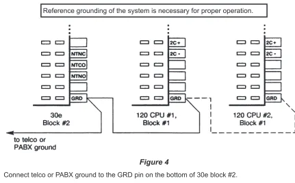
Reference Grounding
Reference grounding of the 30e120 system is necessary for proper operation. This ground should be referenced to within 3 volts of telco ground.
Attendant Consoles
The consoles should be installed in a clear work space and away from plants that require frequent watering or counters that tempt the placement of beverages.
Ambient Environmental Requirements
It is recommended that the same environmental conditions be maintained for the consoles as one would maintain for a personal computer (PC) or data terminal.
Power Requirements
Console operating power is provided by the CPUs or a PSE-3 power supply located in the equipment room.
13-102499 Rev. G Page 7
4. Configuration Sheet Preparation
Prior to installation of this system, the Configuration Sheets attached to the back of this manual should be completed with the information listed below. Please leave the Configuration Sheets on site.
System Programmable Features
Factory programmed values have been chosen to accommodate standard central office or PABX operating parameters and generally accepted customer requirements. These values may be adjusted to specific needs.
A space is provided on the Configuration Sheet for the Directed Call Pickup code required by the telephone system.
Station and Line Programmable Features
1. Phone number and name identification for each line.
2. Programmable features for each line (Privacy, Answer Use).
3. Station number and user name identification for each station. Include any additional functions to be dialed with the DSS number, such as anFDprefix.
4. Autodial numbers for spare DSS keys.
30e Configuration Sheet
System Programmable Features
STATION KEY FEATURE DIAL PAD KEYS AVAILABLE VALUES DEFAULT
VALUE ACTUAL VALUE
A ‘ABANDON’
Ring Time 2 - 9, 0
2 - 9 sec,
10 sec 5
5
B ‘RECALL’
Rings 1 - 9, 0
1 - 9 rings,
no recall 3
3
C ‘DCP DIAL’
Sequence 0, 1 first, last
first
(0)
first
D ‘DIAL SPEED’ 6, 0 slow (6 digits/sec),
fast (10 digits/sec)
fast
(0)
fast
E ‘PAUSE’ Time 2 - 9 200 - 900 msec 700
700
F ‘FLASH’ Time 5 - 9, 0 500 - 900 msec,
1 sec 600
500
G
Dial Tone ‘DETECT’
Time
1 - 9, 0
500, 600, 700 msec,
1, 1.2, 1.5, 1.8, 2 sec 700
600
H ‘HOLD’
Recall Time
3 - 6, 9, 1, 2, 0
30 - 60, 90 sec,
2, 3 min, no recall 90
60
I
Hold ‘RELEASE’
Time
1 - 8
45, 80, 200, 400, 600, 800 msec
1, 2 sec
600
600
J ‘PARK’
Recall Time
3 - 6, 9, 1, 2
30 - 60, 90 sec,
2, 3 min 90
60
K Night ‘BELL’
Mode 1, 2
lines only, lines + stations
lines only
(1)
lines only
L Queue
‘PRIORITY’ 1 - 4
stations only, stations > lines, lines > stations, lines + stations (FIFO)
FIFO
(4)
FIFO
M ‘ALERT TYPE’ 1, 2, 0 normal ringing,
distinctive ringing, both
both
(0)
both
N ‘RNG TYPE’ 1, 0 long, short short
(0)
short
O ‘SYSTEM
CAMP-ON’ 0, * off, on
off
(0)
on
P ‘RECORD
STATS” 0, * off, on
on
(1)
on
DIRECTED CALL PICKUP CODE
D*7
13-102499 Rev. G Page 9
30e Configuration Sheet
Line Programmable Features
(Default settings for all lines are shown in BOLD ITALICS.)
LINE KEY NO.
LINE NAME I.D. or
SPECIAL USAGE KEY
•
Page•
Night•
Quick Mode•
Override•
Call ParkPRIV. WHEN BUSY ANS. USE RING DELAY (NO RINGING, NO DELAY, 1-9 RINGS)
TELEPHONE NUMBERS O F F O N O F F O N
1
local 1
X
X
no
delay
555-1980
2
local 2
X
X
no
delay
555-1981
3
local 3
X
X
no
delay
555-1982
4
local 4
X
X
no
delay
555-1983
5
WATS band 0
X
X
no
delay
208-3559
6
WATS band 5
X
X
no
delay
280-7290
7
Hilldale FX
X
X
no
delay
287-4739
8
9
10
11
Page key
X
X
no
ring
N/A
12
13
Quick Mode key
X
X
14
Override key
X
X
no
ring
N/A
15
Call Park key
X
X
no
120 (#1) Configuration Sheet, DSS Keys 1-60
DSS keys are numbered vertically on the console.
DSS KEY
DSS / AUTODIAL NUMBER (24 digits max.)
USER NAME (14 characters max.)
DSS KEY
DSS / AUTODIAL NUMBER (24 digits max.)
USER NAME (14 characters max.)
1
FD4710
John F
31FD4740
Susan R
2
FD4719
Bill Jones
32FD4742
Rick T
3
FD4729
Jill K
33FD4743
Linda P
4
FD4711
Jane W
34FD4741
Ralf C
5
FD4712
Ronnie Y
35FD4744
Greg O
6
FD4715
Kim L
36FD4747
Sally T
7
FD4720
Jack S
37FD4745
Bob W
8
FD4716
William F
38FD4746
Clint E
9
FD4717
Sarah S
39FD4748
Don R
10
FD4718
Robin R
40FD4749
Katy C
11
FD4721
John L
41FD4750
John F
12
FD4722
Bill T
4213
FD4737
Mike N
4314
FD4736
David T
4415
FD4723
Wayne K
4516
FD4713
Phillip R
4617
FD4714
Mary S
4718
FD4724
Steven E
4819
FD4725
Karen G
4920
FD4726
Robert T
5021
FD4727
Jim W
5122
FD4728
Pat K
5223
FD4730
Randy A
5324
FD4731
Kirk B
5425
FD4732
Cliff M
5526
FD4738
Paul C
5627
FD4739
Norm D
5728
FD4733
Art S
5829
FD4734
Jo P
5930
FD4735
Larry E
6013-102499 Rev. G Page 11
Installation
Contents of Shipping Boxes
The Tone Commander 30e120 system is shipped in four boxes: one for each console, and one for each Central Processing Unit (CPU). Please compare the contents of these boxes with the lists below. Contact your distributor if any items are missing or damaged.
30e Console Box:
(1) 30e console (1) Attendant’s Guide (2) 7´ line cords (1) Quick Reference Card (1) handset with cord (31) clear keycaps
(1) handset cradle (4) sheets of keycap labels (2) cradle mounting screws
30e CPU Box:
(1) 30e CPU (1) mounting template
(1) 30e120 Installation Instructions (3) cable retainers
120 Console Box:
(1) 120 console (1) Attendant’s Guide (1) 7´ line cord (1) Quick Reference Card (1) 12” line cord (61) clear keycaps
(1) console tie bracket (2) sheets of keycap labels (4) tie bracket mounting screws
120 CPU Box:
(1) 120 CPU (1) mounting template
(1) 30e120 Installation Instructions (4) cable retainers
Important Safety Instructions
1. Never install telephone wiring during a lightning storm.
2. Never install telephone jacks in wet locations unless the jack is
specifically designed for wet locations.
3. Never touch uninsulated telephone wires or terminals unless the
telephone line has been disconnected at the network interface.
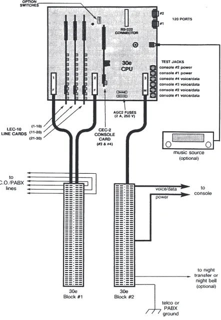
CPU Installation
Refer to Figures 1 and 2.
Mounting CPUs
Refer to Figure 5.
1. Fasten a plywood sheet to the wall with hardware suitable for the wall material. The sheet should have enough room for all 30e and 120 CPUs, and any required ancillary equipment such as expansion console and night bell power supplies.
2. Using the supplied mounting template, mark and pre-drill the mounting holes for the 30e CPU.
Make sure that the CPU mounting location is within 5 feet of a standard 117 VAC, 60 Hz grounded power outlet.
Allow at least one foot of free space above and below the CPU for ventilation.
3. Drive in four suitable fasteners (such as #10×¾" pan head tapping screws), leaving the heads out ¼".
4. Remove the two cover screws, turn each CPU cover fastener so that the slots are horizontal, then remove the cover.
When installation and testing are completed, replace the cover, turn each cover fastener so that the slots are vertical, then lock it in place with the cover screws to assure compliance with UL requirements.If the cover screws need to be replaced, use 6-32×1/4" pan head machine screws.
5. Hang the 30e CPU on the four mounting screws and tighten the screws.
6. Repeat steps 2-5 for each 120 CPU.
Two 120 CPUs are required for systems that will monitor 121-240 stations.
7. Repeat steps 2-5 for each PSE-3 Expansion Power Supply. Only two mounting screws are required for each power supply.
Each 30e or 120 CPU can power two consoles. PSE-3 power supplies are required for systems with three or four consoles at each attendant position. One PSE-3 can power three 30e or 120 consoles.
Blocks
30e
1. Label each side of two split terminal blocks as shown in the Connector Designation columns of Tables 1 and 2.
2. Mount the blocks to the plywood sheet below the 30e CPU, using suitable fasteners.
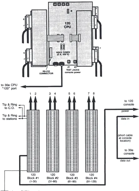
120
1. Label each side of four split terminal blocks as shown in the Connector Designation columns of Tables 3-6.
NOTE– Some cables and blocks may be omitted if the system will monitor less than 120 stations. Each cable has connections for 15 stations. Block #1 is required for console power.
2. Mount the blocks to the plywood sheet below the 120 CPU, using suitable fasteners.
13-102499 Rev. G Page 13
Tone Commander 30e120 Installation Instructions
PSE-3
1. Label one side of a terminal block as shown in the Connector Designation column of Table 7.
2. Mount the block to the plywood sheet near the other system blocks, using suitable fasteners.
Cabling to Blocks
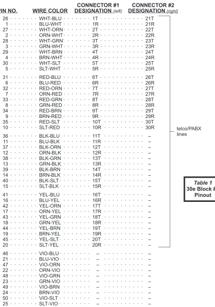
1. Punch down the cables to the blocks as shown in the Wire Color columns of Tables 1-7.
2. Plug the 25 pair cables into the appropriate CPU or power supply connectors. Route the cables through the slots at the bottom of the housings.
3. Secure the cables with the supplied connector clamps.
30e Expansion Cards
The basic 30e CPU can accommodate 20 attendant lines and two consoles. One LEC-10 Line Expansion Card (10 additional lines) and/or a CEC-2 Console Expansion Card (two additional consoles) may be installed in the 30e CPU to expand the system to 30 attendant lines and four consoles.
LEC-10 Line Card
The CPU is supplied with two LEC-10s installed in the leftmost slots, for attendant lines 1-20.
Plug the expansion LEC-10 into the connectors on the 30e CPU board. The components should face the right side of the 30e CPU.
CEC-2 Console Card
Plug the CEC-2 into the connectors in the center of the 30e CPU main circuit board. The components should face the right side of the CPU.
NOTE– A PSE-3 power supply is required for console positions #3 and #4. This unit can power three 30e and/or 120 consoles.
13-102499 Rev. G Page 15
Tone Commander 30e120 Installation Instructions
CONNECTOR #1
CONNECTOR #2
PIN NO.
WIRE COLOR
DESIGNATION
(left)DESIGNATION
(right)26 · · · WHT-BLU · · · 1T · · · 21T 1 · · · BLU-WHT · · · 1R · · · 21R 27 · · · WHT-ORN · · · 2T · · · 22T 2 · · · ORN-WHT · · · 2R · · · 22R 28 · · · WHT-GRN` · · · 3T · · · 23T 3 · · · GRN-WHT · · · 3R · · · 23R 29 · · · WHT-BRN · · · 4T · · · 24T 4 · · · BRN-WHT · · · 4R · · · 24R 30 · · · WHT-SLT · · · 5T · · · 25T 5 · · · SLT-WHT · · · 5R · · · 25R
31 · · · RED-BLU · · · 6T · · · 26T 6 · · · BLU-RED · · · 6R · · · 26R 32 · · · RED-ORN · · · 7T · · · 27T 7 · · · ORN-RED · · · 7R · · · 27R 33 · · · RED-GRN · · · 8T · · · 28T 8 · · · GRN-RED · · · 8R · · · 28R 34 · · · RED-BRN · · · 9T · · · 29T 9 · · · BRN-RED · · · 9R · · · 29R 35 · · · RED-SLT · · · 10T · · · 30T 10 · · · SLT-RED · · · 10R · · · 30R
36 · · · BLK-BLU · · · 11T · · · – 11 · · · BLU-BLK · · · 11R · · · – 37 · · · BLK-ORN · · · 12T · · · – 12 · · · ORN-BLK · · · 12R · · · – 38 · · · BLK-GRN · · · 13T · · · – 13 · · · GRN-BLK · · · 13R · · · – 39 · · · BLK-BRN · · · 14T · · · – 14 · · · BRN-BLK · · · 14R · · · – 40 · · · BLK-SLT · · · 15T · · · – 15 · · · SLT-BLK · · · 15R · · · –
41 · · · YEL-BLU · · · 16T · · · – 16 · · · BLU-YEL · · · 16R · · · – 42 · · · YEL-ORN · · · 17T · · · – 17 · · · ORN-YEL · · · 17R · · · – 43 · · · YEL-GRN · · · 18T · · · – 18 · · · GRN-YEL · · · 18R · · · – 44 · · · YEL-BRN · · · 19T · · · – 19 · · · BRN-YEL · · · 19R · · · – 45 · · · YEL-SLT · · · 20T · · · – 20 · · · SLT-YEL · · · 20R · · · –
46 · · · VIO-BLU · · · – · · · – 21 · · · BLU-VIO · · · – · · · – 47 · · · VIO-ORN · · · – · · · – 22 · · · ORN-VIO · · · – · · · – 48 · · · VIO-GRN · · · – · · · – 23 · · · GRN-VIO · · · – · · · – 49 · · · VIO-BRN · · · – · · · – 24 · · · BRN-VIO · · · – · · · – 50 · · · VIO-SLT · · · – · · · – 25 · · · SLT-VIO · · · – · · · –
13-102499 Rev. G Page 17
Tone Commander 30e120 Installation Instructions
telco/PABX lines
Table 1
30e Block #1
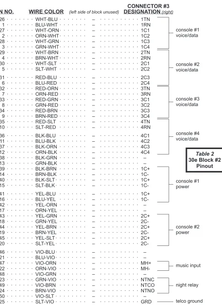
CONNECTOR #3
PIN NO.
WIRE COLOR
(left side of block unused)DESIGNATION
(right)26 · · · WHT-BLU · · · – · · · 1TN 1 · · · BLU-WHT · · · – · · · 1RN 27 · · · WHT-ORN · · · – · · · 1C1 2 · · · ORN-WHT · · · – · · · 1C2 28 · · · WHT-GRN · · · – · · · 1C3 3 · · · GRN-WHT · · · – · · · 1C4 29 · · · WHT-BRN · · · – · · · 2TN 4 · · · BRN-WHT · · · – · · · 2RN 30 · · · WHT-SLT · · · – · · · 2C1 5 · · · SLT-WHT · · · – · · · 2C2
31 · · · RED-BLU · · · – · · · 2C3 6 · · · BLU-RED · · · – · · · 2C4 32 · · · RED-ORN · · · – · · · 3TN 7 · · · ORN-RED · · · – · · · 3RN 33 · · · RED-GRN · · · – · · · 3C1 8 · · · GRN-RED · · · – · · · 3C2 34 · · · RED-BRN · · · – · · · 3C3 9 · · · BRN-RED · · · – · · · 3C4 35 · · · RED-SLT · · · – · · · 4TN 10 · · · SLT-RED · · · – · · · 4RN
36 · · · BLK-BLU · · · – · · · 4C1 11 · · · BLU-BLK · · · – · · · 4C2 37 · · · BLK-ORN · · · – · · · 4C3 12 · · · ORN-BLK · · · – · · · 4C4 38 · · · BLK-GRN · · · – · · · – 13 · · · GRN-BLK · · · – · · · – 39 · · · BLK-BRN · · · – · · · 1C+ 14 · · · BRN-BLK · · · – · · · 1C-40 · · · BLK-SLT · · · – · · · 1C+ 15 · · · SLT-BLK · · · – · · ·
1C-41 · · · YEL-BLU · · · – · · · 1C+ 16 · · · BLU-YEL · · · – · · · 1C-42 · · · YEL-ORN · · · – · · · – 17 · · · ORN-YEL · · · – · · · – 43 · · · YEL-GRN · · · – · · · 2C+ 18 · · · GRN-YEL · · · – · · · 2C-44 · · · YEL-BRN · · · – · · · 2C+ 19 · · · BRN-YEL · · · – · · · 2C-45 · · · YEL-SLT · · · – · · · 2C+ 20 · · · SLT-YEL · · · – · · ·
2C-46 · · · VIO-BLU · · · – · · · – 21 · · · BLU-VIO · · · – · · · – 47 · · · VIO-ORN · · · – · · · MH+ 22 · · · ORN-VIO · · · – · · · MH-48 · · · VIO-GRN · · · – · · · – 23 · · · GRN-VIO · · · – · · · NTNC 49 · · · VIO-BRN · · · – · · · NTCO 24 · · · BRN-VIO · · · – · · · NTNO 50 · · · VIO-SLT · · · – · · · – 25 · · · SLT-VIO · · · – · · · GRD
Table 2
30e Block #2
CONNECTOR #1
CONNECTOR #2
PIN NO.
WIRE COLOR
DESIGNATION
(left)DESIGNATION
(right)26 · · · WHT-BLU · · · T1 · · · T16 1 · · · BLU-WHT · · · R1 · · · R16 27 · · · WHT-ORN · · · T2 · · · T17 2 · · · ORN-WHT · · · R2 · · · R17 28 · · · WHT-GRN · · · T3 · · · T18 3 · · · GRN-WHT · · · R3 · · · R18 29 · · · WHT-BRN · · · T4 · · · T19 4 · · · BRN-WHT · · · R4 · · · R19 30 · · · WHT-SLT · · · T5 · · · T20 5 · · · SLT-WHT · · · R5 · · · R20
31 · · · RED-BLU · · · T6 · · · T21 6 · · · BLU-RED · · · R6 · · · R21 32 · · · RED-ORN · · · T7 · · · T22 7 · · · ORN-RED · · · R7 · · · R22 33 · · · RED-GRN · · · T8 · · · T23 8 · · · GRN-RED · · · R8 · · · R23 34 · · · RED-BRN · · · T9 · · · T24 9 · · · BRN-RED · · · R9 · · · R24 35 · · · RED-SLT · · · T10 · · · T25 10 · · · SLT-RED · · · R10 · · · R25
36 · · · BLK-BLU · · · T11 · · · T26 11 · · · BLU-BLK · · · R11 · · · R26 37 · · · BLK-ORN · · · T12 · · · T27 12 · · · ORN-BLK · · · R12 · · · R27 38 · · · BLK-GRN · · · T13 · · · T28 13 · · · GRN-BLK · · · R13 · · · R28 39 · · · BLK-BRN · · · T14 · · · T29 14 · · · BRN-BLK · · · R14 · · · R29 40 · · · BLK-SLT · · · T15 · · · T30 15 · · · SLT-BLK · · · R15 · · · R30
41 · · · YEL-BLU · · · – · · · – 16 · · · BLU-YEL · · · – · · · – 42 · · · YEL-ORN · · · 1C+ · · · – 17 · · · ORN-YEL · · · 1C-· · · – 43 · · · YEL-GRN · · · 1C+ · · · – 18 · · · GRN-YEL · · · 1C-· · · – 44 · · · YEL-BRN · · · 1C+ · · · – 19 · · · BRN-YEL · · · 1C-· · · – 45 · · · YEL-SLT · · · – · · · – 20 · · · SLT-YEL · · · – · · · –
46 · · · VIO-BLU · · · 2C+ · · · – 21 · · · BLU-VIO · · · 2C-· · · – 47 · · · VIO-ORN · · · 2C+ · · · – 22 · · · ORN-VIO · · · 2C-· · · – 48 · · · VIO-GRN · · · 2C+ · · · – 23 · · · GRN-VIO · · · 2C-· · · – 49 · · · VIO-BRN · · · – · · · – 24 · · · BRN-VIO · · · – · · · – 50 · · · VIO-SLT · · · – · · · – 25 · · · SLT-VIO · · · GRD · · · –
13-102499 Rev. G Page 19
Tone Commander 30e120 Installation Instructions
Table 3
120 Block #1
CONNECTOR #3
CONNECTOR #4
PIN NO.
WIRE COLOR
DESIGNATION
(left)DESIGNATION
(right)26 · · · WHT-BLU · · · T31 · · · T46 1 · · · BLU-WHT · · · R31 · · · R46 27 · · · WHT-ORN · · · T32 · · · T47 2 · · · ORN-WHT · · · R32 · · · R47 28 · · · WHT-GRN · · · T33 · · · T48 3 · · · GRN-WHT · · · R33 · · · R48 29 · · · WHT-BRN · · · T34 · · · T49 4 · · · BRN-WHT · · · R34 · · · R49 30 · · · WHT-SLT · · · T35 · · · T50 5 · · · SLT-WHT · · · R35 · · · R50
31 · · · RED-BLU · · · T36 · · · T51 6 · · · BLU-RED · · · R36 · · · R51 32 · · · RED-ORN · · · T37 · · · T52 7 · · · ORN-RED · · · R37 · · · R52 33 · · · RED-GRN · · · T38 · · · T53 8 · · · GRN-RED · · · R38 · · · R53 34 · · · RED-BRN · · · T39 · · · T54 9 · · · BRN-RED · · · R39 · · · R54 35 · · · RED-SLT · · · T40 · · · T55 10 · · · SLT-RED · · · R40 · · · R55
36 · · · BLK-BLU · · · T41 · · · T56 11 · · · BLU-BLK · · · R41 · · · R56 37 · · · BLK-ORN · · · T42 · · · T57 12 · · · ORN-BLK · · · R42 · · · R57 38 · · · BLK-GRN · · · T43 · · · T58 13 · · · GRN-BLK · · · R43 · · · R58 39 · · · BLK-BRN · · · T44 · · · T59 14 · · · BRN-BLK · · · R44 · · · R59 40 · · · BLK-SLT · · · T45 · · · T60 15 · · · SLT-BLK · · · R45 · · · R60
41 · · · YEL-BLU · · · – · · · – 16 · · · BLU-YEL · · · – · · · – 42 · · · YEL-ORN · · · – · · · – 17 · · · ORN-YEL · · · – · · · – 43 · · · YEL-GRN · · · – · · · – 18 · · · GRN-YEL · · · – · · · – 44 · · · YEL-BRN · · · – · · · – 19 · · · BRN-YEL · · · – · · · – 45 · · · YEL-SLT · · · – · · · – 20 · · · SLT-YEL · · · – · · · –
46 · · · VIO-BLU · · · – · · · – 21 · · · BLU-VIO · · · – · · · – 47 · · · VIO-ORN · · · – · · · – 22 · · · ORN-VIO · · · – · · · – 48 · · · VIO-GRN · · · – · · · – 23 · · · GRN-VIO · · · – · · · – 49 · · · VIO-BRN · · · – · · · – 24 · · · BRN-VIO · · · – · · · – 50 · · · VIO-SLT · · · – · · · – 25 · · · SLT-VIO · · · – · · · –
Table 4
120 Block #2
Pinout
CONNECTOR #5
CONNECTOR #6
PIN NO.
WIRE COLOR
DESIGNATION
(left)DESIGNATION
(right)26 · · · WHT-BLU · · · T61 · · · T76 1 · · · BLU-WHT · · · R61 · · · R76 27 · · · WHT-ORN · · · T62 · · · T77 2 · · · ORN-WHT · · · R62 · · · R77 28 · · · WHT-GRN · · · T63 · · · T78 3 · · · GRN-WHT · · · R63 · · · R78 29 · · · WHT-BRN · · · T64 · · · T79 4 · · · BRN-WHT · · · R64 · · · R79 30 · · · WHT-SLT · · · T65 · · · T80 5 · · · SLT-WHT · · · R65 · · · R80
31 · · · RED-BLU · · · T66 · · · T81 6 · · · BLU-RED · · · R66 · · · R81 32 · · · RED-ORN · · · T67 · · · T82 7 · · · ORN-RED · · · R67 · · · R82 33 · · · RED-GRN · · · T68 · · · T83 8 · · · GRN-RED · · · R68 · · · R83 34 · · · RED-BRN · · · T69 · · · T84 9 · · · BRN-RED · · · R69 · · · R84 35 · · · RED-SLT · · · T70 · · · T85 10 · · · SLT-RED · · · R70 · · · R85
36 · · · BLK-BLU · · · T71 · · · T86 11 · · · BLU-BLK · · · R71 · · · R86 37 · · · BLK-ORN · · · T72 · · · T87 12 · · · ORN-BLK · · · R72 · · · R87 38 · · · BLK-GRN · · · T73 · · · T88 13 · · · GRN-BLK · · · R73 · · · R88 39 · · · BLK-BRN · · · T74 · · · T89 14 · · · BRN-BLK · · · R74 · · · R89 40 · · · BLK-SLT · · · T75 · · · T90 15 · · · SLT-BLK · · · R75 · · · R90
41 · · · YEL-BLU · · · – · · · – 16 · · · BLU-YEL · · · – · · · – 42 · · · YEL-ORN · · · – · · · – 17 · · · ORN-YEL · · · – · · · – 43 · · · YEL-GRN · · · – · · · – 18 · · · GRN-YEL · · · – · · · – 44 · · · YEL-BRN · · · – · · · – 19 · · · BRN-YEL · · · – · · · – 45 · · · YEL-SLT · · · – · · · – 20 · · · SLT-YEL · · · – · · · –
46 · · · VIO-BLU · · · – · · · – 21 · · · BLU-VIO · · · – · · · – 47 · · · VIO-ORN · · · – · · · – 22 · · · ORN-VIO · · · – · · · – 48 · · · VIO-GRN · · · – · · · – 23 · · · GRN-VIO · · · – · · · – 49 · · · VIO-BRN · · · – · · · – 24 · · · BRN-VIO · · · – · · · – 50 · · · VIO-SLT · · · – · · · – 25 · · · SLT-VIO · · · – · · · –
13-102499 Rev. G Page 21
Tone Commander 30e120 Installation Instructions
Table 5
120 Block #3
Pinout
CONNECTOR #7
CONNECTOR #8
PIN NO.
WIRE COLOR
DESIGNATION
(left)DESIGNATION
(right)26 · · · WHT-BLU · · · T91 · · · T106 1 · · · BLU-WHT · · · R91 · · · R106 27 · · · WHT-ORN · · · T92 · · · T107
2 · · · ORN-WHT · · · R92 · · · R107 28 · · · WHT-GRN · · · T93 · · · T108
3 · · · GRN-WHT · · · R93 · · · R108 29 · · · WHT-BRN · · · T94 · · · T109
4 · · · BRN-WHT · · · R94 · · · R109 30 · · · WHT-SLT · · · T95 · · · T110
5 · · · SLT-WHT · · · R95 · · · R110
31 · · · RED-BLU · · · T96 · · · T111 6 · · · BLU-RED · · · R96 · · · R111 32 · · · RED-ORN · · · T97 · · · T112 7 · · · ORN-RED · · · R97 · · · R112 33 · · · RED-GRN · · · T98 · · · T113
8 · · · GRN-RED · · · R98 · · · R113 34 · · · RED-BRN · · · T99 · · · T114
9 · · · BRN-RED · · · R99 · · · R114 35 · · · RED-SLT · · · T100 · · · T115 10 · · · SLT-RED · · · R100· · · R115
36 · · · BLK-BLU · · · T101 · · · T116 11 · · · BLU-BLK · · · R101· · · R116 37 · · · BLK-ORN · · · T102 · · · T117 12 · · · ORN-BLK · · · R102· · · R117 38 · · · BLK-GRN · · · T103 · · · T118 13 · · · GRN-BLK · · · R103· · · R118 39 · · · BLK-BRN · · · T104 · · · T119 14 · · · BRN-BLK · · · R104· · · R119 40 · · · BLK-SLT · · · T105 · · · T120 15 · · · SLT-BLK · · · R105· · · R120
41 · · · YEL-BLU · · · – · · · – 16 · · · BLU-YEL · · · – · · · – 42 · · · YEL-ORN · · · – · · · – 17 · · · ORN-YEL · · · – · · · – 43 · · · YEL-GRN · · · – · · · – 18 · · · GRN-YEL · · · – · · · – 44 · · · YEL-BRN · · · – · · · – 19 · · · BRN-YEL · · · – · · · – 45 · · · YEL-SLT · · · – · · · – 20 · · · SLT-YEL · · · – · · · –
46 · · · VIO-BLU · · · – · · · – 21 · · · BLU-VIO · · · – · · · – 47 · · · VIO-ORN · · · – · · · – 22 · · · ORN-VIO · · · – · · · – 48 · · · VIO-GRN · · · – · · · – 23 · · · GRN-VIO · · · – · · · – 49 · · · VIO-BRN · · · – · · · – 24 · · · BRN-VIO · · · – · · · – 50 · · · VIO-SLT · · · – · · · – 25 · · · SLT-VIO · · · – · · · –
Table 6
120 Block #4
Pinout
Data Link Cable
1. Plug the supplied data link cable to the "30e" port on the 120 CPU.
2. Plug the other end of the cable to the lower "120" port on the 30e CPU.
3. Route the cable through the slots at the bottom of the CPU housings.
4. Excess cable must be stored in the 120 CPU as shown to assure FCC Part 15 compliance.
Secure with a cable tie.
5. If this installation has two 120 CPUs (121-240 stations), connect the second 120 CPU to the upper "120" port on the 30e CPU.
Reference Grounding
1. Connect telco or PABX ground to the GRD pin on the bottom of 30e block #2.
2. For each 120 CPU, connect telco or PABX ground to the GRD pin on the bottom right of 120 block #1. These connections may be "daisy chained" as shown.
DO NOT connect this reference ground to the metal housing of any CPU or power supply!
CPU Chassis Grounding
This ground connection is required for safety and EMI shielding. It is usually provided by the 3rd wire on the CPU power cords. If the integrity of the power outlet ground is questionable, use the ground
connection shown below for each 30e and 120 CPU.
1. Connect a solid copper #10 or #12 AWG wire to the ground terminal on the CPU. The wire should be tightly clamped between the ground screw and the cup washer.
2. Connect the wire to an approved ground, such as MGN (multi-grounded neutral) from the power lines, building ground, a metallic cold water pipe, or a grounding rod.
13-102499 Rev. G Page 25
Tone Commander 30e120 Installation Instructions
Reference grounding of the system is necessary for proper operation.
Figure 4
Connections to Telco/PABX Lines
Line Testing
Connect a test telephone to each line; verify the presence of dial tone, and break dial tone by dialing a number.
The 30e allows DTMF tone dialing only – refer to the SYSTEM DESCRIPTION - Telco/PABX Requirements section.
Test any additional features ordered with the lines. Open circuit voltage must be approximately 48 volts.
Station Connections
1. Connect Tip and Ring of each line to the associatedT andRpair on the right side of 30e block #1.
If the 30e is used with a key system, connect to the C.O. side of the line cards.
2. If this installation has stations in parallel with console lines, the stations should be connected to Tip and Ring at the telco/PABX block.
Figure 6
Figure 7
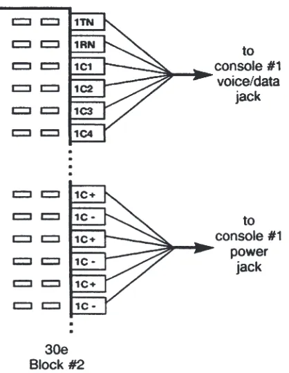
Console Cable Installation
30e Console Cables
Console Positions #1 and #2
Wall Jack Pinout
Wall Jack Typical Wire Color
Console #1 Designation (connector 1)
Console #2 Designation (connector 1)
Typical 3 Pair Console Cable
Wire Color
(actual wire color)
1 WHT 1C3 (WHT-GRN) 2C3 (RED-BLU) WHT-GRN
2 BLK 1C1 (WHT-ORN) 2C1 (WHT-SLT) WHT-ORN
3 RED 1RN (BLU-WHT) 2RN (BRN-WHT) BLU-WHT
4 GRN 1TN (WHT-BLU) 2TN (WHT-BRN) WHT-BLU
5 YEL 1C2 (ORN-WHT) 2C2 (SLT-WHT) ORN-WHT
6 BLU 1C4 (GRN-WHT) 2C4 (BLU-RED) GRN-WHT
Table 8 – 30e Console “Voice/Data” Jack Pinout, Console Positions #1 and #2
13-102499 Rev. G Page 27
Tone Commander 30e120 Installation Instructions
Wall Jack Pinout
Wall Jack Typical Wire Color
Console #1 Designation
Console #2 Designation
Typical 3 Pair Console Cable
Wire Color
(actual wire color)
1 WHT 1C+ (YEL-BLU) 2C+ (YEL-SLT) WHT-GRN
2 BLK 1C+ (BLK-SLT) 2C+ (YEL-BRN) WHT-ORN
3 RED 1C- (BRN-BLK) 2C- (GRN-YEL) BLU-WHT
4 GRN 1C+ (BLK-BRN) 2C+ (YEL-GRN) WHT-BLU
5 YEL 1C- (SLY-BLK) 2C- (BRN-YEL) ORN-WHT
6 BLU 1C- (BLU-YEL) 2C- (SLT-YEL) GRN-WHT
Table 9 – 30e Console “Power” Jack Pinout, Console Positions #1 and #2
All 30e console cables from positions #1 and #2 connect to 30e block #2. The total length of each console cable, including line cord and equipment room cross connects, must not exceed 500 feet.
1. Install two 6 position, 6 contact modular telephone jacks within 6 feet of the console.
2. Label the jacks "30e voice/data" and "30e power".
3. Connect a 3 pair cable to each jack and run them to the equipment room.
IMPORTANT– Whenever nonkey adapters are used in conjunction with existing multipair cable, verify that the adapters conform to Tables 8 and 9 above.
4. Only if the colors of your cables differ from the typical colors: fill out Tables 8 and 9 with the actual wire colors of the cables for each connection.
5. Punch down the "voice/data" cable to block #2 as listed in the Console #1 Designation column in Table 8.
6. Punch down the "power" cable to block #2 as listed in the Console #1 Designation column in Table 9.
7. If the system has two attendant positions, punch down the second console's cables to the pins listed in the Console #2 Designation columns of Tables 8 and 9.
Console Positions #3 and #4 Wall Jack Pinout Wall Jack Typical Wire Color Console #3 Designation Console #4 Designation
Typical 3 Pair Console Cable
Wire Color
(actual wire color)
1 WHT 3C3 (RED-BRN) 4C3 (BLK-ORN) WHT-GRN
2 BLK 3C1 (RED-GRN) 4C1 (BLK-BLU) WHT-ORN
3 RED 3RN (ORN-RED) 4RN (SLT-RED) BLU-WHT
4 GRN 3TN (RED-ORN) 4TN (RED-SLT) WHT-BLU
5 YEL 3C2 (GRN-RED) 4C2 (BLU-BLK) ORN-WHT
6 BLU 3C4 (BRN-RED) 4C4 (ORN-BLK) GRN-WHT
Table 10 – 30e Console “Voice/Data” Jack Pinout, Console Positions #3 and #4
Wall Jack Pinout Wall Jack Typical Wire Color Console #3 Designation Console #4 Designation
Typical 3 Pair Console Cable
Wire Color
(actual wire color)
1 WHT 3C+ (WHT-GRN) 4C+ (RED-GRN) WHT-GRN
2 BLK 3C+ (WHT-ORN) 4C+ (RED-ORN) WHT-ORN
3 RED 3C- (BLU-WHT) 4C- (BLU-RED) BLU-WHT
4 GRN 3C+ (WHT-BLU) 4C+ (RED-BLU) WHT-BLU
5 YEL 3C- (ORN-WHT) 4C- (ORN-RED) ORN-WHT
6 BLU 3C- (GRN-WHT) 4C- (GRN-RED) GRN-WHT
Table 11 – 30e Console “Power” Jack Pinout, Console Positions #3 and #4
A PSE-3 power supply is required for these consoles. Each supply can power three consoles, either 30e or 120 models. All PSE-3s must be powered from the same outlet box or power strip as the 30e and 120
CPUs.
The "power" cables from 30e consoles at positions #3 and #4 must connect to the power supply block. The "voice/data" cables connect to 30e block #2.
The total length of each console cable, including line cord and equipment room cross connects, must not exceed 500 feet.
1. Install the jacks and cables in the same manner as those for positions #1 and #2.
2. Punch down the "voice/data" cables to block #2 as listed in Table 10.
3. Punch down the "power" cables to the PSE-3 block as listed in Table 11.
NOTE– The colors listed in the Console Designation columns of Table 11 show the console at position #3 connected to power output #1, and console at position #4 connected to power output #2. This is just an example; any of the three power outputs may be used (refer to Table 7). The
PSE-3 contains three independent circuits. DO NOT connect them together – use a separate output for each console!
13-102499 Rev. G Page 29
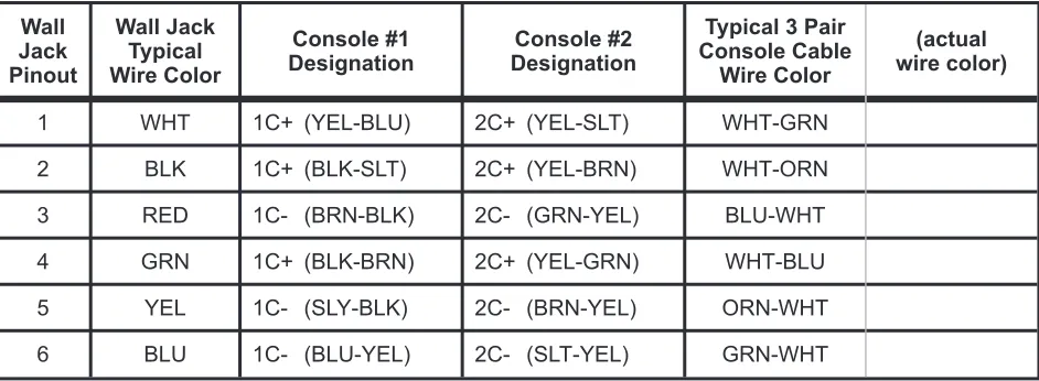
120 Console Cables
Console Positions #1 and #2
Wall Jack Pinout
Wall Jack Typical Wire Color
Console #1 Designation (connector 1)
Console #2 Designation (connector 1)
Typical 3 Pair Console Cable
Wire Color
(actual wire color)
1 WHT 1C+ (YEL-BRN) 2C+ (VIO-GRN) WHT-GRN
2 BLK 1C+ (YEL-GRN) 2C+ (VIO-ORN) WHT-ORN
3 RED 1C- (ORN-YEL) 2C- (BLU-VIO) BLU-WHT
4 GRN 1C+ (YEL-ORN) 2C+ (VIO-BLU) WHT-BLU
5 YEL 1C- (GRN-YEL) 2C- (ORN-VIO) ORN-WHT
6 BLU 1C- (BRN-YEL) 2C- (GRN-VIO) GRN-WHT
Table 12– 120 Console “Power” Jack Pinout, Console Positions #1 and #2
The power cables from consoles #1 and #2 connect to 120 block #1. The total length of each console cable, including line cord and equipment room cross connects, must not exceed 500 feet.
1. Install a 6 position, 6 contact modular telephone jack within 6 feet of the console.
2. Label the jack "120 power".
3. Connect a 3 pair cable to the jack and run it to the equipment room.
IMPORTANT– Whenever nonkey adapters are used in conjunction with existing multipair cable, verify that the adapters conform to Table 12 above.
4. Only if the colors of your cables differ from the typical colors: fill out Table 12 with the actual wire colors of the cable for each connection.
5. Punch down the cable to 120 block #1 as listed in the Console #1 Designation column in Table 12.
6. If the CPU has two attendant positions, punch down the second console's cable to the pins listed in the Console #2 Designation columns of Table 12.
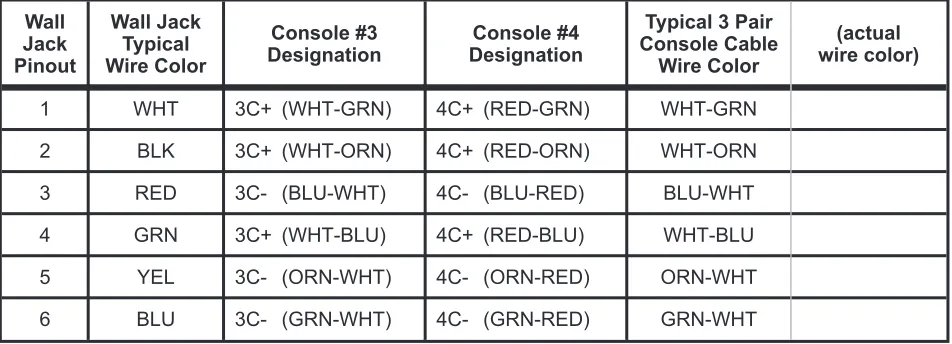
Console Positions #3 and #4
Wall Jack Pinout
Wall Jack Typical Wire Color
Console #3 Designation
Console #4 Designation
Typical 3 Pair Console Cable
Wire Color
(actual wire color)
1 WHT 3C+ (WHT-GRN) 4C+ (RED-GRN) WHT-GRN
2 BLK 3C+ (WHT-ORN) 4C+ (RED-ORN) WHT-ORN
3 RED 3C- (BLU-WHT) 4C- (BLU-RED) BLU-WHT
4 GRN 3C+ (WHT-BLU) 4C+ (RED-BLU) WHT-BLU
5 YEL 3C- (ORN-WHT) 4C- (ORN-RED) ORN-WHT
6 BLU 3C- (GRN-WHT) 4C- (GRN-RED) GRN-WHT
Table 13 – 120 Console “Power” Jack Pinout, Console Positions #3 and #4
A PSE-3 power supply is required for these consoles. Each supply can power three consoles, either 30e or 120 models.
The "power" cables from 120 consoles at attendant positions #3 and #4 connect to the power supply block.
The total length of each console cable, including line cord and equipment room cross connects, must not exceed 500 feet.
1. Install the jacks and cables in the same manner as those for console positions #1 and #2.
2. Punch down the "power" cables to the PSE-3 block as listed in Table 13.
NOTE– The colors listed in the Console Designation columns of Table 13 show the console at position #3 connected to power output #1, and the console at position #4 connected to power output #2. This is just an example; any of the three power outputs may be used (refer to Table 7).
The PSE-3 contains three independent circuits. DO NOT connect them together – use a separate output for each console!
13-102499 Rev. G Page 31
Console Installation
Perform the steps in this section for each console position.
30e
120
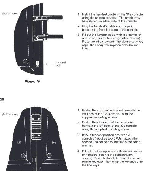
Figure 10
1. Install the handset cradle on the 30e console using the screws provided. The cradle may be installed on either side of the console.
2. Plug the handset's cable into the jack beneath the front left edge of the console.
3. Fill out the keycap labels with line names or numbers (refer to the configuration sheets). Place the labels beneath the clear plastic key caps, then snap the keycaps onto the line keys.
(bottom view)
Figure 11
1. Fasten the console tie bracket beneath the left edge of the 120 console using the supplied mounting screws.
2. Fasten the other end of the tie bracket beneath the left edge of the 30e console using the supplied mounting screws.
3. If the attendant position has two 120 consoles (requires two CPUs), attach the second 120 console to the first in the same manner.
4. Fill out the keycap labels with station names or numbers (refer to the configuration sheets). Place the labels beneath the clear plastic key caps, then snap the keycaps onto the line keys.
Console Line Cords
1. Plug one end of each supplied 6 conductor modular line cord into the “voice/data” and “power” jacks at the back of the 30e console.
2. Plug the line cords into their associated wall jacks, or into the test jacks located on the 30e CPU main circuit board (refer to Figure 1).
CAUTION– Do not interchange these two line cords!
3. Plug the supplied short modular line cord into the “data out” jack on the 30e console, and into the “data in” jack on the first 120 console.
Do not use a standard modular cord– these data cords have the connections reversed on one plug.
4. If the system has two 120 consoles at the attendant position (requires two 120 CPUs) – plug the other short modular line cord into the “data out” jack on the first 120 console, and into the “data in” jack on the second 120 console.
5. Plug one end of each supplied long 6 conductor modular line cord into the “power” jacks at the back of each 120 console.
6. Plug these cables into their associated wall jacks, or into the test jacks located on the 120 CPU main circuit board (refer to Figure 2).
If a line cord (other than the short 120 data cord) must be replaced, be sure to use one with 6 conductors. Many line cords with 6 position plugs have only 4 conductors.
13-102499 Rev. G Page 33
Tone Commander 30e120 Installation Instructions
Preliminary Testing
At this time, you should have completed the following: · Mounted the CPU and blocks
· Mounted the power supplies and blocks for console positions #3 and #4 (optional) · Installed line and console expansion cards (optional)
· Installed the cables from the CPU to the blocks
· Installed the data link cable between 30e and 120 CPUs · Connected telco reference ground to 30e and 120 blocks · Connected Tip and Ring from each line to the 30e block
· Connected Tip and Ring from each monitored station to the 120 blocks · Installed the console cables and jacks
· Assembled and connected the console(s)
It is a good idea to briefly test the operation of the 30e before proceeding with installation or programming.
1. Plug the CPU into a power outlet.
A. The "heartbeat" indicator at the bottom of the CPU main circuit board should flash.
If no "heartbeat" is present, check that the power outlet is "live". A blown fuse on the circuit board may indicate a defective CPU.
B. The console should emit two triple beeps, then briefly display "30e OK".
If these indications are not observed, check both voice/data and power cabling.
2. Repeat step 1 at attendant position #2, #3, and #4 if the system is so equipped.
C.O. Line Testing
Perform the following tests on each telco/PABX line. Repeat at attendant position #2, #3, and #4 if the system is so equipped.
Line Access and Imbalance Testing
1. Press the key representing the line to be tested.
The associated line lamp (telephone symbol) should flicker while the line is accessed.
NOTE– Open circuit voltage must be approximately 48 volts.
2. Listen for audible hum or excessive noise.
PASS – Such noise or hum is not present. FAILURE – Such noise or hum is present.
3. Listen for dial tone.
PASS – Dial tone is heard. FAILURE – Dial tone is not heard.
4. Break dial tone by dialing a digit.
PASS- Dial tone is broken and no audible hum or excessive noise is heard.
5. Press the RELEASE key.
IMPORTANT– Upon the detection of any failure during the foregoing testing, disconnect the affected equipment from the telephone line to determine if such equipment is the cause of failure. Any equipment determined to be malfunctioning must remain disconnected, and use discontinued until the malfunction has been corrected.
Hold and Autohold Testing
1. Access the line to be tested and establish call to another station.
2. Place the call on hold by depressing the red HOLD key.
The associated H indicator will wink slowly.
3. Reseize the call by depressing the line key.
The associated H indicator goes out.
The line lamp flickers while the line is accessed.
4. Place the call on autohold by depressing another idle line key.
The line accessed draws dial tone. The line under test goes to autohold.
5. Release the line drawing dial tone and reseize, then release the line under test.
Ring Trip and Imbalance Testing
1. Dial the number of the line to be tested from another station.
The associated line lamp will flash slowly.
or
The associated line lamp will flash quickly, if the line has been optioned for ring delay.
2. Press the line key to answer the call.
The line lamp changes from flashing to flickering.
3. Listen for audible hum or excessive noise.
PASS – Such noise or hum is not present. FAILURE – Such noise or hum is present.
IMPORTANT– Upon detection of audible hum or excessive noise, disconnect the affected equipment to determine if such equipment is the cause of failure. Any equipment determined to be malfunctioning must remain disconnected, and use discontinued until the malfunction has been corrected.
4. Press the RELEASE key.
13-102499 Rev. F Page 35
30e CPU Option Switches
SWITCH FUNCTION
1 OFF – Autodial Program unlocked ON – Autodial Program locked
2 OFF – Configuration Program unlocked ON – Configuration Program locked
3 OFF – Name Program unlocked ON – Name Program locked
4 OFF – night transfer ON – night ringing
5 must be OFF!
6, 7 not used
8
OFF – retain new programming ON – restore defaults
(when power is cycled off & on)
Table 14 – CPU Option Switches
Switches on the CPU control system programming and Night Service options. The switches are ON when set towards the left side of the CPU. When a programming option is "locked", programming changes are not allowed. The switch location is shown on page 15.
Optional Equipment Installation
The following options require system programming for proper operation. Refer to the Configuration Programming section.
Night Service
The 30e console may either switch the telephone system to night transfer, or ring a night bell during incoming ringing when the attendant selects Night Service mode. Only one of these options may be installed.
Night Ringing
Night ringing is switched on and off during ringing of either lines only, or lines and stations. One of these options must be selected during configuration programming.
Tone Commander's PA-24 Paging/Chime Module provides a chime tone that can announce ringing calls over a paging system. This unit is powered from the 30e or 120 CPU. Refer to the PA-24 Paging/Chime Module Installation Instructions, doc. #13-102595.
An external bell may be used in place of ringing over a paging system, as shown below.
Night Transfer
The night transfer leads from the telephone system remain connected together when the console is in Night Service mode, and during a power interruption at the 30e CPU.
13-102499 Rev. G Page 37
Tone Commander 30e120 Installation Instructions
1. Install the night bell in the location desired by the customer.
2. Run a two conductor cable from the night bell to the equipment room.
3. Connect the cable to the bell.
4. Mount a suitable bell power supply in the equipment room.
5. Connect one output terminal of the power supply toNTCO(common) on the right side of 30e block #2.
6. Connect one wire in the bell cable to the other output terminal of the power supply.
7. Connect the remaining wire in the bell cable toNTNO(normally open).
Figure 13
ConnectNTCO(common) andNTNC (normally closed) on the right side of CPU block #1 to the night control terminals on the telco/PABX block.
Music On Hold
An external music source is required for Music On Hold. It will be assigned to the lines during configuration programming. The music input may be connected to any type of compatible music source (refer to the Specifications section).
The music source can be connected to the jack provided on the 30e CPU, or punched down to the block.
Jack Connections
Block Connections
1. Connect an RCA-type phono plug to one end of a single conductor shielded cable, or obtain a cable with a plug attached. The center conductor connects to the pin of the plug.
2. Plug the cable into the music input jack at the top of the 30e CPU.
3. Connect the other end of the cable to the output of the music source. A plug to fit the music source may be required.
Figure 15
1. Connect a twisted wire pair toMH+and MH-on the right side of 30e block #2.
2. Connect the other end of the wire pair to the output of the music source. A plug to fit the music source may be required.
Paging
Tone Commander's PA-24 Paging/Chime module interfaces the 30e console to a paging system. The module includes a night ringing chime and switching for background music control. Power is derived from the 30e or 120 CPU.
Paging can be connected to any spare line key on the 30e. Refer to the PA-24 Paging/Chime Module Installation Instructions, doc. #13-102595.
Voice Mail
Each station with an associated voice mail box should be call forwarded on no answer to the voice mail system. The DSS dial string for these stations must include the R (Ringback Detect) option, as described on page 65.
If Call Forward-No Answer is not available, program a spare DSS key with the voice mail access number. Call transfer to voice mail is handled manually in the same manner as transfer to a station.
13-102499 Rev. G Page 39
Configuration Programming
Various network interface and operation parameters are programmable by the installer, allowing compatibility with a wide variety of central offices and PABXs. The system is pre-programmed at the factory; many installations will require few changes to these values. Programming is retained in the CPU's memory when power is disconnected. When option switch #8 on the 30e CPU isOFF, programming is retained in the 30e CPU's memory when power is disconnected.
The programmable parameters are described on the following pages in the order listed below. A parameter or feature may be altered at any time without reprogramming the entire system.
The following features may be set from configuration programming mode by pressing the appropriate line key. The letters are printed on the console front panel beneath the line keys. Key numbers in parentheses correspond to line numbers on the punchdown blocks.
1. System-wide Features
Line Key Feature
A (26) Abandoned Ring Time I (24) Hold Release Time B (27) Recall Rings J (25) Park Recall Time C (28) Pickup Code Sequence K (16) Night Bell Mode D (29) Dialing Speed * L (17) Queue Priority
E (30) Pause Time M (18) Alert Type
F (21) Hookflash Time * N (19) Ringing Type G (22) Dial Tone Detect Time * O (20) Camp-on
H (23) Hold Recall Time P (11) Statistics Recording
2. Special Feature Key Assignment
S (14) Assign Page Key U (6) Assign Night Key * V (7) Assign Quick Mode Key * W (8) Assign Override Key * X (9) Assign Call Park Key
3. Features Selectable By Line
* Q (12) Line Privacy * R (13) Answer Use
After configuration programming is completed, program the following items as described in subsequent sections of this manual.
4. DSS/Autodial Numbers * 6. Ring Delays
5. Name Displays 7. Time of Day Clock
Using Configuration Programming Mode
The configuration programming mode must be entered prior to attempting any of the following
programming procedures.Enter this mode only when the console is idle, i.e., no calls are in progress or on hold and the time of day is displayed.
The Configuration Program Lock Switch (switch #2) inside the 30e CPU must beOFF(unlocked) before proceeding (see pages 15 and 36).
To enter configuration programming mode: · Press HOLD.
· Press TRANSFER. · Press RELEASE. · Press dial pad key C (2).
The display will indicate that configuration programming mode has been entered.
To exit configuration programming mode and store all programming: · Press RELEASE.
or
The mode will be exited automatically 1 minute after the last keypress.
When completed, set the Configuration Program Lock Switch inside the 30e CPU toON(locked) to prevent inadvertent changes to the programmed settings.
Line keys on the 30e console are used to select the feature to be programmed – letters identifying the
keys are printed beneath the keys on the console's front panel.
Default Settings
The default settings, as shipped from the factory, are listed with each feature on the following pages.
Default settings may be recalled by setting 30e CPU option switch #8 toON, then cycling the CPU power off and on (pull out the power plug for a few seconds). Set this switch back to OFF to prevent losing
your programming during a power outage.
The switch location is shown on pages 15 and 36.
Confirmation and Error Tones
The speaker in the console signals correct or incorrect actions during programming. The console's volume control adjusts the level of the tones – use the VOL keys above the dial pad.
Confirmation Tone – double beep Error Tone – single beep
Help Displays
The console display shows current settings during programming, and displays help information. Displays longer than 20 characters will automatically scroll to the left after a brief pause.
Help with selecting a feature to be programmed is available by pressing TRANSFER. Help will be displayed continuously until either a feature is selected, configuration programming mode is exited by pressing RELEASE, or the help display is restarted by pressing TRANSFER again.
After selecting a feature with a line key, help with programming that feature can be displayed by pressing the line key again. The console will return to programming value selection following the help display.
13-102499 Rev. G Page 41
13-102499 Rev. G Page 43
Tone Commander 30e120 Installation Instructions
Programming System-Wide Features
Timing Parameters and Night Service Mode
· Press HOLD, then TRANSFER, then RELEASE, then C (2) on the dial pad to enter configuration programming mode.
"CONFIGURE PROG" will be displayed.
· Press a line key to select the feature to be programmed. The display will show the item name and the current value. The station status lamp will light steadily.
· Press a key on the dial pad if you want to change the value.
The new value will be shown in the display. Changes are stored immediately.
· Press a DSS key to select another feature. or
Press RELEASE to exit configuration programming mode (the mode will be exited automatically 1 minute after the last keypress).
NOTE– Systems with two or more attendant console positions have separate Queue Priority, Ringing Type, and Camp-On settings for each console. They must be programmed individually at each console position.
For example, to set Hold Recall Time to 50 seconds:
13-102499 Rev. G Page 45
Tone Commander 30e120 Installation Instructions
Timing values listed in the following tables are nominal, and may differ slightly from the actual values. Shaded values are factory defaults.
Abandoned Ring Time
Dial Pad Key Available Values
2 2 sec
3 3 sec
4 4 sec
5 5 sec
6 6 sec
7 7 sec
8 8 sec
9 9 sec
0 10 sec
Table 15
Recall Rings
(with 120 console only)
Dial Pad Key Available Values
1 1 ring
2 2 rings
3 3 rings
4 4 rings
5 5 rings
6 6 rings
7 7 rings
8 8 rings
9 9 rings
0 no recall
Table 16
Line key to select feature: A
Default value: 5 sec
This parameter determines the timing for discontinuing ringing of unanswered incoming calls that were abandoned by the caller. It should be set to the next time value longer than the silent interval between ringing bursts.
if too short– each ring burst may be seen as a new call. This can cause erratic line lamp rates and loss of ringing delays.
if too long– abandoned calls will continue to ring for the duration of this timing value.
Line key to select feature: B
Default value: 3 rings
This sets the number of rings before a call transferred to an idle station recalls the console.
Pickup Code Sequence
(with 120 console only)
Dial Pad Key Available Values
0 first
(before station #)
1 last
(after station #)
Table 17
Dialing Speed
Dial Pad Key Available Values
6 slow (6 digits/sec) 0 fast (10 digits/sec)
Table 18
Pause Time(with 120 console only)
Dial Pad Key Available Values
2 200 ms
3 300 ms
4 400 ms
5 500 ms
6 600 ms
7 700 ms
8 800 ms
9 900 ms
Table 19
13-102499 Rev. G Page 47
Tone Commander 30e120 Installation Instructions
Line key to select feature: C
Default value: first
This parameter determines when the console inserts the Directed Call Pickup code during a station call pickup dialing sequence, as required by the telephone system.
Almost all installations require the pickup code to befirst.
Line key to select feature: D
Default value: fast
The tone autodialing speed (via DSS key) is set with this parameter.
Use the dialing speed compatible with the central office or PABX. If misdialing occurs with the fast speed, switch to slow speed.
Manual dialing speed is also affected. Whenfastspeed is selected, manually dialed digits follow dial pad keystrokes. With slowspeed selected, digits are buffered and sent with a tone on period of 80 ms, and 80 ms between digits. This guarantees minimum tone periods for slow central offices.
Line key to select feature: E
Default value: 700 ms
This sets the length of a "pause" in an autodial sequence.
Pauses are typically used to insert a delay in a dialing string when calling voice mail or similar equipment. Change this parameter if a delay other than a multiple of 700 ms is required.
Hookflash Time
Dial Pad Key Available Values
5 500 ms
6 600 ms
7 700 ms
8 800 ms
9 900 ms
0 1 sec
Table 20
Dial Tone Detect Time
(with 120 console only)
Dial Pad Key Available Values
1 500 ms
2 600 ms
3 700 ms
4 1 sec
5 1.2 sec
6 1.5 sec
7 1.8 sec
8 2 sec
Table 21
Line key to select feature: F
Default value: 600 ms
This parameter sets the length of a timed hookflash generated during call transfer and autodial operations. The default value is adequate for most systems.
if too short– receipt of second dial tone may be intermittent during call transfer operations.
if too long– the calling party may be disconnected during call transfer operations.
Line key to select feature: G
Default value: 700 ms
This sets the time steady dial tone must be present before station digits are autodialed.