Smart Security Management in Secure Devices
Bruno Robisson1, Michel Agoyan1, Patrick Soquet2, S´ebastien Le Henaff2, Franck Wajsb¨urt3, Pirouz Bazargan-Sabet3, and Guillaume Phan4 1 CEA/EMSE, Secure Architectures and Systems Laboratory, Centre de Micro´electronique de Provence, 880 Route de Mimet, 13541 Gardanne, France
2 Viaccess-Orca, Les Collines de l’Arche, 92057 La D´efense, France 3 LIP6, 4 Place Jussieu, 75252 Paris, France
4 Trusted Logic, 6 rue de la Verrerie, 92190 Meudon, France
Abstract. Among other threats, secure components are subjected to physical attacks whose aim is to recover the secret information they store. Most of the work carried out to protect these components gener-ally consists in developing protections (or countermeasures) taken one by one. But this “countermeasure-centered” approach drastically decreases the performance of the chip in terms of power, speed and availability. In order to overcome this limitation, we propose a complementary ap-proach: smart dynamic management of the whole set of countermeasures embedded in the component. Two main specifications for such manage-ment are required in a real world application (for example, a conditional access system for Pay-TV): it has to provide capabilities for the chip to distinguish between attacks and normal use cases (without the help of a human being and in a robust but versatile way); it also has to be based on mechanisms which dynamically find a trade-off between security and performance. In this article, a prototype which enables such security management is described. The solution is based on a double-processor architecture: one processor embeds a representative set of countermea-sures (and mechanisms to define their parameters) and executes the ap-plication code. The second processor, on the same chip, applies a given security strategy, but without requesting sensitive data from the first processor. The chosen strategy is based on fuzzy logic reasoning to en-able the designer to describe, using a fairly simple formalism, both the attack paths and the normal use cases. A proof of concept has been pro-posed for the smart card part of a conditional access for Pay-TV, but it could easily be fine-tuned for other applications.
Keywords: Hardware tamper resistance, Countermeasures against fault and
1
Introduction
Security is a key component for information technologies and communication. Among the security threats, a very important one is certainly due to vulnerabili-ties of the integrated circuits that implement cryptographic algorithms to ensure confidentiality, authentication or data integrity (such as smartcards). With the access to one of these circuits, the attacker tries either to reconstruct the func-tionality of the circuit (reverse engineering) or to recover cryptographic materials when the cryptographic algorithm is known (physical or hardware cryptanaly-sis). Both threats share a set of techniques. The first one, called side channel attacks, consists in observing some physical characteristics which are modified during the circuit’s computation [25, 40, 39, 16, 9]. The second technique, called
fault attacks, consists in disrupting the circuit’s behavior [11, 35, 8, 37, 3, 17]. The third one consists in getting information about the chip design by direct inspec-tion of its structure [42]. This inspecinspec-tion may be performed by using any kind of imaging techniques or by using destructive means such as abrasion, chemical etching or focused ion beam. Combinaison of those three techniques have also been proposed [7, 36].
Many protections have therefore been proposed to counter such attacks. Some protections (hereafter referred to as “sensors”) give information about the state of the system either by measuring the light, the voltage, the frequency or the temperature of the chip or by detecting errors during computations. This detec-tion is generally based on spatial redundancy (i.e. performing the same compu-tation several times simultaneously), temporal redundancy (i.e. performing the same computation several times) or information redundancy (i.e. performing a computation with more bits than required) [30, 31, 12] or ad-hoc sensors [19, 23]. Several mechanisms are also proposed to detect a modification in the software execution flow. In some cases, an additional hardware block is dedicated to this task [5, 28]. To render physical attacks more difficult, “noise” has been added, for example, by using an internal clock, by randomizing the order of the instruc-tions, by adding dummy operations or by masking the internal computations that can be predicted by the attacker [34, 14, 2, 10, 15]. Another way to reduce sensitivity to side channel attacks consists in reducing the correlation between physical values (such as power consumption or electromagnetic radiation) and the data processed, for example, by using balanced data encoding and balanced place and route [22, 33, 38], by using power filters or electromagnetic shields. Fi-nally, some countermeasures modify the functional behavior of the circuit in case of attacks. Such “reactions” may consist, for example, in temporarily stopping the communication with the reader (the card “mutes”) and/or resetting parts of the running software. The ultimate reaction consists in permanently destroying (i.e. killing) all the data (including sensitive information) stored in the chip.
a complementary approach: implementing complex management (through the application of a “strategy of security”) of the whole set of countermeasures em-bedded on a chip. Such a “system-level” approach has already been addressed in [21]. The authors proposed mechanisms which reconfigure the architecture of cryptographic hardware blocks embedded in an FPGA in accordance with performance and energy consumption criteria. Our work addresses this trade-off but also the trade-trade-off between security and availability. Besides, we consider that these trade-offs have to be adjusted only with technologies which are regu-larly available in smart cards (i.e. without the use of hardware reconfiguration capabilities provided by FPGAs).
In section 2, a representative case study (a conditional access system for Pay-TV) and the associated expected properties for complex strategy of security are detailed. In section 3, an example of such a strategy, based on fuzzy logic, is proposed. In section 4, an innovative hardware/software prototype enabling the execution of this strategy is described. Finally, in section 5, the results obtained with this prototype are presented.
2
Case study
In the following sections, an implementation of the chosen representative system, the smart card part of a conditional access system (hereafter referred to as the “host system”), is described. Its functional parts and some of its protections are presented. Finally, by expressing the difficulties of designing such a system, the specifications for complex strategies of security are highlighted.
2.1 Conditional Access System: Functional Part
The functional part of the conditional access system (or CAS) consists of a JavaCard application which is interpreted by a virtual machine (VM) which runs on a micro-controller.
Virtual Machine: In order to be as close as possible to a real product and in order to benefit from the efficient software security features, a state-of-the-art virtual machine (VM) has been implemented in the host system. The chosen VM complies with the Java Card 2.2.2 specifications [24], and provides card content management capabilities based on the GlobalPlatform Standard [20]. Hence, it is possible to download and install on-card applications (or applets) running on top of the VM and to use standard Java Card and GlobalPlatform Application Programming Interfaces (APIs).
Host’s micro-controller: The host sub-system is built on a 5-stage pipelined 32-bit Harvard RISC microcontroller able to execute one instruction per clock cycle. The instructions are stored in 640kB of ROM and the data in 256kB of RAM and in 128kB of EEPROM. The peripherals include two Universal Asynchronous Receiver Transmitters (or UARTs) compliant with the ISO7816 and RS232 standards and an Advanced Encryption Standard (or AES) crypto-engine (to accelerate the ciphering and deciphering of data) [32].
2.2 Protections
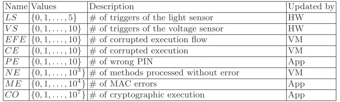
The different components of the host described above embed the protections described below. Some of them, such as the security sensors, may have out-puts. Other countermeasures may be configured. Configuration parameters are either integer numbers (for redundancy level, insertion of dummy instructions and random power generator) or boolean values (which activate or not a security reaction). As will be explained in section 4.1, even though these protections are physically embedded in the host sub-system, these parameters are not driven by the host.
Security sensors Several sensors have been implemented or emulated. Some
of them measure physical characteristics such as voltage, light intensity or chip temperature. Others detect errors during the execution flow of a piece of code, during I/O data transmissions or during computations. One way of detecting errors consists in performing the same computation several times and then com-paring the results. If they are identical, the computation is considered error-free. If not, a counter of corrupted executions, notedCE, is increased. The number of times that the same computation is performed is called the “redundancy level” (noted “RL”). A redundancy level of “i” is noted “×i”. It is equal to 1 when the redundancy countermeasure is not activated but when 3≤RL, the host has fault-tolerance capabilities.
between 0 and 104. Another sensor is the number of times that a cryptographic operation is performed with the same key. This number is notedCO.
Name Values Description Updated by
LS {0,1, . . . ,5} # of triggers of the light sensor HW
V S {0,1, . . . ,10} # of triggers of the voltage sensor HW
EF E {0,1, . . . ,10} # of corrupted execution flow VM
CE {0,1, . . . ,10} # of corrupted execution VM
P E {0,1, . . . ,10} # of wrong PIN App
N E {0,1, . . . ,103}# of methods processed without error VM
M E {0,1, . . . ,104}# of MAC errors App
CO {0,1, . . . ,107}# of cryptographic execution App
Table 1.Outputs of the CMs
Insertion of Dummy Instructions (IDI) Another protection consists in
increasing the level of noise by inserting dummy instructions (i.e. that are not useful) during computations. The execution of a program is thus made up of several sequences of valid instructions followed by dummy instructions. In our framework, which has been drawn from [4], two parameters D and N config-ure the countermeasconfig-ure.D andN denote the maximum number of consecutive useful and dummy instructions respectively in a sequence. Let us call D the random variable equal to the number of instructions in the sequences of useful instructions. The domain of Dis chosen equal to{1;. . .;D}. Let us callN the random variable equal to the number of instructions in the sequences of useless instructions. The domain of this random variable is set equal to{0;. . .;N}. We consider that the random variablesN andDfollow uniform distributions. Note that N is equal to 0 when the countermeasure is not activated.
Random Power Generator (RPG) In order to blur the power consumption
of the circuit, several Random Number Generators (RNG) may be activated. Assuming that each steptof this power consumption, notedx(t), is drawn from a Gaussian shaped probability distribution (with a mean µc(t) and a constant
standard deviationσc). Let us also suppose that the power consumption added
by one random generator also follows a Gaussian distribution with a constant meanµR and with a standard deviation which is equal toσc. We also suppose
that the different RNG are identical and that their power consumptions are statistically independent. The probability density function of the total power consumption, notedxtot(t), of the circuit whenRRNG are activated is thus the
following:
pdf(xtot(t)) =
e−
(xtot(t)−µc(t)−R·µR)2 2·σ2c·(1+R2 )
σc·√1 +R2·√2·π
Note thatRis equal to 0 when the RPG countermeasure is not activated.
Security reactions Two reactions have been taken into account: stopping the
communication and resetting the software (hereafter noted “Mute/Reset”), or destroying all the data (hereafter noted “kill”). But several reactions could also be considered at the application level: forbidding the access to one or several TV channel packages, suppressing services such as video on demand, restricting the access to only free TV or program contents, etc.
Other protections In the case of a commercial device, other security features
(such as power filters, shields, balanced logic, etc.) which can never be deac-tivated, are also supposed to protect the circuit, independently of all kinds of strategy of security.
2.3 Impact of protections
In this section, the impact on the performances and on the security of the pa-rameters of the countermeasures described above is analyzed theoretically.
Performance criteria An estimation of the evaluation of performances in
terms of speed, energy consumption and security is proposed above. Note that we consider only the threat related to side channel attacks (SCA) and differential fault attacks (DFA). In order to successfully mount such attacks, the attacker proceeds in a divide and conquer manner (i.e. he attacks small pieces of the key one by one). On each iteration of these attacks, he targets the result of one particular piece of computation, hereafter referred to the “targeted result”. It is, for example for SCA, the computation of a SBox during the first round. To mount a DFA, the attacker also needs the cipher text resulting from one or several faulty computations [26].
– The gain in terms of SCA, notedF SCA, is the ratio between the number of curves needed for the attacker to recover the key when the countermeasure is activated and the number of curves without countermeasure (the greater the better).
– The gain in terms of DFA, notedF DF A, is the ratio between the number of experiments needed to recover the key when the countermeasure is activated and the number of experimentations without countermeasure (the greater the better).
– The loss in terms of speed, notedF T ime, is the ratio between the duration of a computation with the countermeasure and the duration of the same computation without countermeasure (the smaller the better).
– The loss in terms of energy, noted F N RJ, is the ratio between the en-ergy consumption with countermeasure and the enen-ergy consumption without countermeasure (the smaller the better).
Impact of Redundancy
FSCA: We consider that the redundant computations generate identical power traces which could easily be added in the time domain by the attacker, decreasing the number of curves needed to recover the key by a factorRL.
FDFA: As explained in section 2.2, a redundant computation is associated with a comparison of the results in order to increment the counterCEif the results are different. To bypass the redundancy protection, the attacker will have to both avoid the update of the counter in case of error detection and realize several faults of the same value, notede0, during theRLsuccessive computations of the targeted result. The probability of realizing such a set of faults determines the number of realizations which are required to mount the attack. We shall call q
the number of bits of the targeted result. If we consider that all the faults on these bits are equally probable, then the probability of realizing the same fault
e0 (whose value does not matter) during the RL successive execution of the targeted instruction is equal to (1/2q)RL−1. In classical DFA schemes, a fault generally has to affect 1 byte. So, the default value is chosen equal toq= 8.
FTime: In our framework, the redundant computations are not performed in parallel. We also assume that the comparison of the results is negligible in terms of computation time. Thus, the redundancy countermeasure increases the com-putation time by a factorRL.
FNRJ: We assume that the comparison of the results is negligible in terms of energy consumption. So, the redundancy countermeasure increases the energy consumption by a factorRL.
F SCARL= 1
RL F DF ARL= (1/2q)RL
−1
F T imeRL=RL
F N RJRL=RL
Fig. 1.Performances for the redundancy level countermeasure
Impact of Insertion of Dummy Instructions Suppose that the mth valid
AES [32]. Let us define the random variableX equal to the number of the clock cycle associated with the execution of the instructionm. Each realization xof this random variable, is equal to x= Pki=1(di) +Pki=1(ni), with k such that
Pk
i=1(di) =m, withibeing the ith sequence of useless/useful instructions and
with di and ni theith realizations respectively of the random variablesD and
N. We havex=m+Pki=1(ni). We consider that, becausem≫D,xcould be
approximated byx∼m+Pqi=1(ni) withq= 2·m/(D+ 1). In these conditions,
the density of probability ofX follows a normal distribution (µX,σX) with:
µX =m+q·µN =m·(1 +N/2) (2)
σ2X=q·σN2 =m·
N·(N+ 2)
6·(D+ 1) (3)
For the sake of simplicity, we consider, as proposed in [13], thatm is uniformly distributed (with the probability 1 out of 2·σX) between m−σX andm+σX.
FSCA: In these conditions, the SCA peak is reduced by a factor 2·σX and the
number of curves necessary to retrieve the key increases by a factor 4·σ2
X. But
by using the sliding window method (with consists in reconstructing the peak by integrating the consumption curves on 2·σX samples) also described in [13],
this saving in terms of number of power curves is only equal to 2·σX.
FDFA: In order to realize a DFA, we suppose that the attacker is able to target clock cycles comprising between m−σX and m+σX. In these conditions, he
has one chance out of 2·σX to modify the instructionm. The number of faulty
realizations is thus increased by a factor 2·σX.
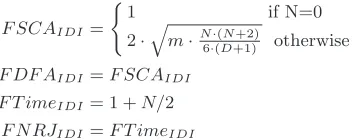
FTime: The formula 2 indicates that the computation time is increased by a factor (1 +N/2).
FNRJ: Because we consider that useful and dummy instructions consume the same energy, the consumption of the circuit is also increased by a factor of (1 +N/2).
F SCAIDI=
(
1 if N=0
2·qm·N·(N+2)
6·(D+1) otherwise
F DF AIDI=F SCAIDI
F T imeIDI= 1 +N/2
F N RJIDI=F T imeIDI
Impact of Random Power Generator
FSCA: According to [13], if we callδ the amplitude of the SCA peak (i.e. the difference of the power consumption or electromagnetic radiation between data) and σc the standard deviation of the power consumption curve, the number of
power curves necessary to recover the key has to be higher than (σc/δ)2. The
activation of theRrandom generators increases this number by a factor (1+R2).
FDFA: We suppose that the RPG does not protect against differential fault attacks.
FTime: As the RPG processes at the same time as the computation, computa-tion time is not increased by its activacomputa-tion.
FNRJ: We consider that the power consumption of an RNG is equal toαtimes the temporal mean ofµc(t) (withα= 10% because the random number generator
is a small piece of hardware). In these conditions, the total energy consumption of the circuit is increased by a factor (1 +α·R).
F SCARP G= 1 +R2
F DF ARP G= 1
F T imeRP G= 1
F N RJRP G= (1 +α·R)
Fig. 3.Performances for the RPG countermeasures
Combination of countermeasures When the different countermeasures are
combined, factors computed above for the different countermeasures are simply multiplied for side-channel attacks, for the time of computation and the energy consumption. For the DFA, the chance of making the same fault (in order to bypass detection of RL) on the targeted result (whose position is blurred with IDI) is equal to the chance obtained in the first occurrence (i.e. 1/(2q·2·σ
X))
up to the redundancy level minus one. So we obtain:
Figure 5 displays the values of these factors for different values ofD andN
(withRL= 2 andR= 3). Note that the values do not share the same scale. This figure clearly shows that performance decreases as the security level increases.
2.4 Difficulties
F SCA=F SCARP G·F SCAIDI·F SCARL
F DF A=F DF ARP G·F DF ARL
−1
IDI ·F DF ARL
F T ime=F SpeedRP G·F SpeedIDI·F SpeedRL
F N RJ =F N RJRP G·F N RJIDI·F N RJRL
Fig. 4.Performances for combination of the countermeasure
Fig. 5.Decrease of the performances with the increase of the security
– Its security level has to be very high: the security of a smart card is expected to hold for 2-5 years. But it is generally used for 8 years. In this condition, a card which resists one additional year represents large savings for the content and CAS providers.
– Its performance has to be high: For Pay-TV applications, the switch from channel to channel has to be as fast as possible.
– The availability has to be high: A malfunction of the card causes a prejudice for the user (who is no longer able to watch his favorite TV program) but also for the CAS provider who has to deal with expensive field feedback. A malfunction may be due to abnormal system usage (if the card, for example, is put in a very hot place) but also to incorrect system integration (if the card, for example, is inserted in a poor quality reader). Such cases will further be called “anomalies”, in the sense that the component operates in abnormal conditions but is not subjected to attacks.
word (CW) during the period of validity of the key EK. With this CW, he gains access to the content. So, the corruption of the key EK is a very serious security threat. On the contrary, knowing the value of the word CM at a given moment is of little value because it is only valid for a very short period of time.
– Its power consumption must be low if it is embedded in a mobile phone or in a multimedia tablet.
– It has to be inexpensive.
2.5 Specifications for strategies of security
Section 2.3 shows that the setup of the countermeasures defines the performances of the circuit in terms of security, speed and power consumption (but also avail-ability). This section also shows that those performances are closely linked. For example, the increase in security causes the decrease in speed. Thus, the set of performances which may be reached, despite the wide range of setups of the countermeasures, is restricted. This restriction may be such that none of the per-formances of this set fulfills the specifications described above. In such a case, the specifications are antagonistic and the designer has to make a trade-off. He has, for example, to choose between availability and security.
We propose to add mechanisms which enable to dynamically modify the se-tups of the countermeasures, i.e. which enable to switch from a high performance but “poorly” secured state to a low performance but secured one. To draw an analogy, these mechanisms provide a new “degree of freedom” which make it possible to reach new sets of performances. In other words, these mechanisms release the links that exist between the different performances. We consider that a smart strategy of security should be able to control these mechanisms to fulfill all the specifications (or at least as many as possible).
3
Example of strategy of security
One way to reduce these rates consists in applying methods proposed in Intru-sion Detection Systems (or IDS) [6]. The first method consists in determining the whole set of states of the system reached by a user with “normal” behavior. Each time the state of the system leaves this set, an “anomaly” is detected. The second method is complementary. It consists in determining the whole set of states which would have to be reached by an evil-minded user to perform an attack. When the system enters this set, misuse (considered an attack) is detected. Contrary to classical IDS, the component is off-line most of the time. So, it has to react autonomously without any outside help. In order to obtain, in this context, both robust and secure behavior, mechanisms must detect both anomalies and misuses.
According to principles developed for IDS, the chosen strategy of security is decomposed into three different processes: The first consists in collecting infor-mation about the state of the host system, the second in computing the anomaly and misuse levels and the third in modifying the parameters of the countermea-sures.
3.1 Information sources
We consider that the sensitivity level of data DS (provided by the applica-tion and defined in 2.1) and the outputs{LS, V S, EF E, CE, P E, N E, M E, CO} (provided by the sensors and defined in section 2.2) are the inputs of the analysis algorithm. More generally, each input is calledSiand takes its valuessibetween
0 and Si
max, with Smaxi chosen as a multiple of 5. Note that, for clarity, when
only one input is taken into account, the superscriptiis omitted. The vector of all the inputs’ values is calledS ={s0, . . . , sj}.
3.2 Analysis
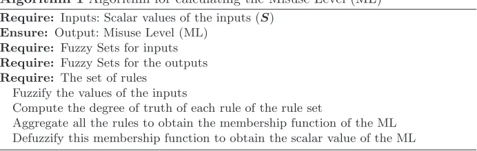
As the secure circuit designer generally expresses the anomaly and misuse cases with words which are very often vague and inaccurate, fuzzy logic has been used to formalize the analysis mechanism [43, 18]. Within this framework, the detec-tion process is mainly described by a set of “IF-THEN” rules (expressed with words or “linguistic variables” whose meanings are precisely defined with “fuzzy sets”) and an inference process (i.e. computing the misuse and anomaly level (resp. ML and AL). This process can be activated, for example, each time an in-put value is modified. The process chosen for inferring a decision from fuzzy rules and inputs was first proposed by Mamdani in [27]. As reported in the following pseudo-code, this process consists in fuzzifying the inputs, then computing the degree of truth of the rules, then aggregating the results of these rules and lastly “defuzzyfying” them to obtain the output values. Only the computation of the misuse level is described in detail below (the computation of the anomaly level being strictly identical).
Algorithm 1Algorithm for calculating the Misuse Level (ML)
Require: Inputs: Scalar values of the inputs (S)
Ensure: Output: Misuse Level (ML)
Require: Fuzzy Sets for inputs
Require: Fuzzy Sets for the outputs
Require: The set of rules Fuzzify the values of the inputs
Compute the degree of truth of each rule of the rule set
Aggregate all the rules to obtain the membership function of the ML Defuzzify this membership function to obtain the scalar value of the ML
Definition The significance of the words (or “linguistic variables”) “low” and “high” for the inputs and outputs are defined with “fuzzy subsets”. The mem-bership function, denoted µA, of a fuzzy subset A is a generalization of the
characteristic function in classical set theory. It is any function mapping the val-uessof the inputS to the real unit interval [0,1]. The valueµA(s) is called the membership degree ofs in the fuzzy subsetA. This degree quantifies the grade of membership of the element s to the fuzzy subsetA: the value 0 means that
s is not a member of the fuzzy set; the value 1 means that s is a full member of the fuzzy set. The values between 0 and 1 characterize fuzzy members, which belong to the fuzzy set only partially. The degree of membership also quantifies the degree of truth of the assertion “s is A” (which is true with a degreeµA(s)).
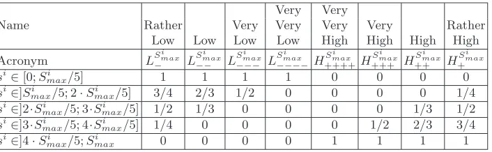
Membership functions for inputs Firstly consider the fuzzy sets associated with the value of the inputSi. The 8 membership functions (or fuzzy subsets) selected
for each input Si are presented in Table 6. For example, let us consider the
voltage sensor input whose maximum value is equal to V Smax = 10. If this
input is equal to 3 (and so is comprised between V Smax/5 and 2·V Smax/5) it
is considered “rather high” with a grade of truth of 1/4 and “very low” with a grade of truth of 1/2. If this voltage sensor value is equal to 7 (and so is comprised between 3·V Smax/5 and 4·V Smax/5) it is considered “high” with a
grade of truth of 2/3 and “very very low” with a grade of 0.
Membership functions for outputs The outputs of the analysis mechanisms are the levels of anomaly and misuse. Their values are real values in [0,1]. The two different membership functions “LOW” and “HIGH”, considered for these outputs are described in Table 2:
Name LOW HIGH
o∈[0; 0,2] 1 0
o∈]0,2; 0,8]−5/3·o+ 2/3 5/3·o−1/3
o∈]0,8; 1] 0 1
Name
Very Very
Rather Very Very Very Very Rather
Low Low Low Low High High High High
Acronym LSmaxi
− L Si max −− L Si max −−− L Si max −−−−H Si max ++++H Si max +++ H Si max ++ H Si max +
si∈[0;Si
max/5] 1 1 1 1 0 0 0 0
si∈]Si
max/5; 2·S i
max/5] 3/4 2/3 1/2 0 0 0 0 1/4
si∈]2·Si
max/5; 3·Simax/5] 1/2 1/3 0 0 0 0 1/3 1/2
si∈]3·Si
max/5; 4·Simax/5] 1/4 0 0 0 0 1/2 2/3 3/4
si∈]4·Si
max/5;Simax 0 0 0 0 1 1 1 1
Fig. 6.The 8 membership functions (or fuzzy subsets) for an inputSi ( Si
max is the maximum value of this input)
Set of Rules The security rules are expressed in terms of “IF-THEN” rules. The
“IF” term is the premise (or precondition). The “THEN” term is the conclusion. The premises are generally expressed as boolean operations on fuzzy subsets.
Operations on fuzzy subsets The boolean operations such as AND, OR and NOT are also defined in fuzzy logic. In the following, we consider the standard Zadeh operators on fuzzy subsets A0 and A1 respectively defined on variable xand y such as:
Z N OT :µN OT(A0)(x) = 1−µA0(x)
Z AN D:µAN D(A0,A1)(x, y) = min(µA0(x), µA1(y))
Z OR:µOR(A0,A1)(x, y) = max(µA0(x), µA1(y))
The extension ofZ AN DandZ ORto “n-ary” operators is trivially defined and denoted as:
µAN D(A0,...,Ak)(x0, . . . , xk) = min(µA0(x0), . . . , µAk(xk))
=mink
j=0(µAj(xj))
µOR(A0,...,Ak)(x0, . . . , xk) = max(µA0(x0), . . . , µAk(xk))
=maxk
j=0(µAj(xj))
Example of rules set Two examples of rules notedR0andR1expressed with nat-ural language are reported above. They are also expressed in two more compact but equivalent ways by using the notation described above.
The degree of truth of the premise is a real number in [0,1] which depends on the values S of the inputs. This degree of truth of the premise of the rule
i is denoted prei(S). As described in Table 7, we distinguish the rules which
R0
IF the number of PIN code error is rather high OR the number of triggers of the voltage sensor is high THEN the misuse is high
IF (P EisH+ ORV SisH++) THEN Misuse is HIGH IFµOR(H+,H+++)(P E, V S) THENµHIGH(M isuse)
R1
IF the number of methods that have processed without error is very high THEN the misuse is low
IF (N EisH+++ ) THEN Misuse is LOW IFµH+++(N O E) THENµLOW(M isuse)
Table 3.Examples of rules set
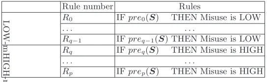
of security is expressed in our system by using several rules (about a dozen). Without loss of generality, we reorder the rules so that those numbered from 0 to q−1 are “LOW-m” rules and those numbered from q to p are “HIGH-m” rules. The considered set of rules is notedRand reported in Figure 7.
Rule number Rules
L
O
W
-m
R0 IFpre0(S) THEN Misuse is LOW
. . . .
Rq−1 IFpreq−1(S) THEN Misuse is LOW
H
IG
H
-m
Rq IFpreq(S) THEN Misuse is HIGH
. . . .
Rp IFprep(S) THEN Misuse is HIGH
Fig. 7.Considered set of rulesR
Compute the degree of truth of the rules
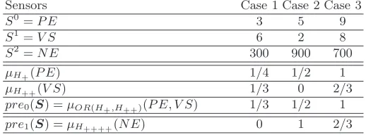
Computing the values of the premises The degree of truth of each premise is computed first by evaluating the degree of membership of the inputSi to fuzzy
subsets. Then, if necessary, the Zadeh operators are applied according to the premise’s formula. Examples of such computations are reported on Table 8 for three different triplets of input values.
It is important to note that because we have chosen input membership func-tions that are discontinuous and because we have chosen Zadeh operators, re-gardless of the values of the entries and rere-gardless of the different formulæ used to express the premise i, the result prei(S) is always an element of the set
P ={0; 1/4; 1/3; 1/2; 2/3; 3/4; 1};
Sensors Case 1 Case 2 Case 3
S0=P E 3 5 9
S1=V S 6 2 8
S2=N E 300 900 700
µH+(P E) 1/4 1/2 1
µH++(V S) 1/3 0 2/3
pre0(S) =µOR(H+,H++)(P E, V S) 1/3 1/2 1
pre1(S) =µH++++(N E) 0 1 2/3
Fig. 8.Examples of degree of truth of the premises ofR0 andR1
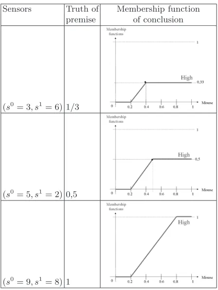
truncating the membership function Ak(y) of the conclusion with the value of
the premise, that is:
µRk(y|S) = min(prek(S), µAk(y))
The modified membership function of the conclusion of rulesR0 andR1 are respectively shown in Figure 9 and 10 for different values of inputs.
In fuzzy logic inference mechanisms, all the rules are considered to fire in parallel. So, at first glance, the use of this logic could lead to inconsistency, that is, several rules could lead to different conclusions (for example, the misuse is both HIGH and LOW). The aim of aggregation of rules and defuzzification is to compute a unique value for the decision.
Aggregation of rules The different rules are considered to be linked together
with the operator OR. So, combining the rules consists in taking for ally∈[0,1], the maximum value of the conclusions of the different rules, according to the following formula:
µR(y|S) =maxp
k=0(µRk(y|
S))
Figure 11 shows the membership functions obtained by combining the rulesR0 andR1 for the three cases described above.
Defuzzification The operation of defuzzification consists in calculating a scalar
Sensors Truth of Membership function premise of conclusion
(s0= 3, s1= 6) 1/3
(s0= 5, s1= 2) 0,5
(s0= 9, s1= 8) 1
Fig. 9.Modification of the membership function according to the value of inputs (rule
R0)
Output membership function rewriting The fuzzy subset ofLOW−mis defined as:
µLOW−m(y|S) = max(min(pre0(S), µLOW(y)),
. . . ,min(preq−1(S), µLOW(y))
= min(max(pre0(S),
. . . , preq−1(S)), µLOW(y))
= min(maxq−1
k=0(prek(
S)), µLOW(y))
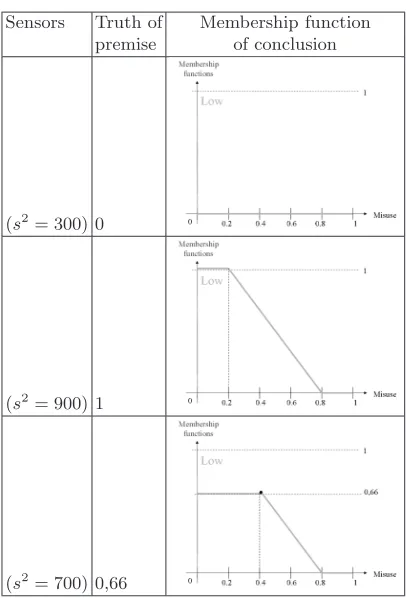
In the same way, the fuzzy set associated to the “HIGH-y” rules is defined as:
µHIGH−m(y|S) = min( p
max
k=q−1(prek(
S)), µHIGH(y))
As explained in section 3.2, the different premises prek are in the set P.
Sensors Truth of Membership function premise of conclusion
(s2= 300) 0
(s2= 900) 1
(s2= 700) 0,66
Fig. 10.Modification of the membership function according to the value of inputs (rule
R1)
µLOW−m(y)ph such as:
pl= q−1 max
k=0(prek(
S))∈P
ph= p
max
k=q(prek(
S))∈P
µLOW−m(y)pl= min(pl, µLOW(y))
µHIGH−m(y)ph = min(ph, µHIGH(y))
The output membership function for the output y can in these conditions always be written in the following form:
µR(y)pl,ph = max(µ
LOW−m(y)pl, µHIGH−m(y)ph)
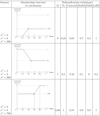
Sensors Membership function Defuzzification techniques of conclusions Pl Ph Centroid MofM FofM LofM
s0= 3
s1= 6
s2= 300
0 0,33 0,65 0,7 0,4 1
s0= 5
s1= 2
s2= 900
1 0,5 0,42 0,1 0 0,2
s0= 9
s1= 8
s2= 700
0,66 1 0,55 0,9 0,8 1
Fig. 11. Membership function of the output according to the value of inputs (com-bination of rulesR0 andR1) and associated crisp values for different defuzzification techniques
max” (MM), “first of max” (FOM) and “last of max” (LM). For example, the FOM crisp value is computed using the formula:
F OM(µ(y)) =min{v∈[0,1]|µ(v) =SU Py∈[0,1]{µ(y)}} (4)
Then, we have computed their values for the whole set of possible values of premises, that is, for all of the 49 membership functionsµR(y)pl,ph withP
h∈P
Ph
FOM 0.00 0.25 0.33 0.50 0.67 0.75 1.00
Pl
0 0 0.35 0.4 0.5 0.6 0.65 0.8 0.25 0 0 0.4 0.5 0.6 0.65 0.8 0.33 0 0 0 0.5 0.6 0.65 0.8 0.5 0 0 0 0 0.6 0.65 0.8
0.66 0 0 0 0 0 0 0.8
0.75 0 0 0 0 0 0 0.8
1 0 0 0 0 0 0 0
Table 4.First of Max results forµR(y)pl,ph
3.3 Configuration of countermeasures
The configuration of the countermeasures has been chosen from the analysis of their impact, described in section 2.3. We have evaluated the impact of the RPG forR∈ {0; 3; 10}(the value for αis chosen equal to 10%). As the cost of the redundancy technique is very high, we have only considered RL∈ {1; 2; 3} (the default value for q is 8) and the impact of the IDI for D ∈ {0; 4; 8} and for N ∈ {2; 3; 4} (the value for m is chosen equal to 150). Among all those possibilities, only four configurations of the different countermeasures are taken into account. These configurations are chosen since they cover a large range of security/performance trade-offs. They are reported in Table 12. It is important to note that whatever the configurations, the different physical sensors are always activated. It is also important to note that, in practice, the security level is determined as the minimum value between F DF A and F SCA(in bold in the table).
Config. Sensors RL RPG IDI Mute or Kill FSCA FDFA Time Energy Reset
Saf e ON ×1 0 (D= 2;N = 0) No No 1,0 1,0 1,0 1,0
U nsaf e ON ×2 3 (D= 3;N = 4) No No 122,5 6270,7 4,0 5,2
Critical ON ×3 10 (D= 4;N = 8) Yes No 1346,71,0E+08 7,8 15,6
F atal - - - Yes
-Fig. 12.Countermeasure configurations
M L
[0; 0.2] ]0.2; 0.4] ]0.4; 0.6] ]0.6; 0.8] ]0.8; 1]
1
−
A
L
[1; 0.8] Saf e Saf e U nsaf e Critical F atal
]0.8; 0.6] Saf e U nsaf e U nsaf e Critical F atal
]0.6; 0.4] U nsaf e U nsaf e U nsaf e Critical F atal
]0.4; 0.2] U nsaf e U nsaf e Critical Critical F atal
]0.2; 0] U nsaf e Critical Critical F atal F atal
Fig. 13. Configurations of the countermeasures according to the Misuse (ML) and Anomaly (AL) Levels
4
Prototyping
This section describes a hardware implementation which has been defined for our case study but which could also be used for different strategies of security.
4.1 Architecture
We choose an architecture, represented in Figure 14, which separates the calcu-lations related to the execution of the application software and those related to the management of the security. This leads to the addition of a system called “monitor” and strictly dedicated to the management of the security. In the left part of the figure, the host system, described in section 2.1, is represented with its software part (the CAS application running above the JavaCard virtual ma-chine) and its hardware part (the 32-bit RISC microcontroller). Each of these parts implements its own set of countermeasures described in section 2.2. These countermeasures may be configured via signals noted “CMs config.” and may give information about the state of the host via signals noted “CMs outputs”. The signal which indicates the sensitivity of the data handled by the application is noted DS. All these signals are exchanged between the host and the monitor through a communication channel. The monitor is represented in the right part of the figure. The software parts of the monitor are the strategy of security and the component-based operating system. Its hardware part is a micro-controller. The hardware and software parts of the monitor and an example of commu-nication between the host and the monitor are described above.
Fig. 14.Architecture of the prototype (hardware in dark grey, software in grey)
the computation of the premises is only the application of min/max operators according to the premises’ formulæ. Also note that, thanks to off-line precom-putations and the choice of the fuzzy sets, the defuzzification is reduced to the access in a table of size 7×7 elements (cf Table 4). The complete strategy can thus be easily implemented in a very simple processor.
Monitor’s micro-controller: The micro-controller of the monitor is built around a 5-stage pipelined 32-bit Harvard RISC processor. To increase the security of the system, this processor does not share any piece of hardware with the host system and in particular it has its own addressing space: the instructions are stored in 32kB of ROM and data in 4kB of RAM. The peripherals comprise one UART, two FIFOs and an Interrupt Controller Unit (ICU). These ICU and FIFOs provide two communication channels: The monitor is informed of the events occurring in the host (without having access to the sensitive data themselves) and in return, the monitor is able to change the configuration of the countermeasures embedded into the host.
Communication between the host and the monitor: The communication between the host and the monitor is based on a request/acknowledge protocol. The re-quest is always initiated by the host. The host waits after its rere-quest until the monitor responds. The following example describes such a communication initi-ated by the application.
1. The application indicates that the sensitivity of the data that it manipulates (DS) is changing.
3. The host stops its current execution.
4. From the fuzzy sets and the fuzzy rules defined by the user, the monitor processes the CM’s outputs and the DS’s value by using the fuzzy reasoning described in section 3.2. The outputs of this reasoning are the misuse and the anomaly levels. These levels are used to select the configuration of the countermeasures thanks to Tables 13 and 12 reported in section 3.3. 5. The monitor asks to the host system to configure software (via FIFOs) and
hard wired countermeasures (via the ICU).
6. The monitor waits until all the countermeasures are configured and are ready. 7. The monitor asks to the host system to resume its execution.
4.2 FPGA synthesis results
The whole system has been implemented in the Xilinx Virtex-5 FPGA of an ML501 evaluation platform. This platform has been extended with an ISO7816 interface adapter (for an easy connection with off-the-shelf smart card readers) and with an additional RS232 serial interface (for trace or debug purposes). The details of the hardware implementation of the host, of the monitor and of the communication channels are described in Figure 15.
4 KB DATA
CM ctrl reg
Timer CODE32 KB UART
32 bits
RISC EE
emulation 128KB SRAM
IT ctrl CODE 896 KB & DATA RNG
Fault Injector Sensors 32 bits
RISC
CM ctrl reg ICU Decoder
Address
Timer Address Decoder
UART ISO7816 UART
RS232 Debug MONITOR HOST SMART CARD EMULATOR
RS232 trace
off−chip ram
probe adaptatorSC
Fig. 15.Hardware part of the prototype
slices out of 7200). So, the combinatorial part of the monitor represents around 40% of the combinatorial part of the whole system. As the resources associated with the memory parts are far larger than the combinatorial ones, the estimated total overhead (i.e. including the memory areas) decreases to about 7%. But it is important to note that this total overhead greatly depends on the size of the host’s memories. For example, for a smaller host (i.e. with 256kB of ROM, 32kB of RAM and 128kB of EEPROM), the total overhead rises to approximately 18%.
5
Results
Different steps have been planned to validate the strategy of security and the associated HW/SW architecture. The first step consists in performing a security analysis of the behavior of the whole system. The second step consists in playing “real-life” scenarios and verifying the responses of the system by simulation. Future work will consist in performing “real” life attacks on the FPGA.
5.1 Security analysis
Side channel analysis For this discussion, we distinguish two kinds of
in-formation leakage. The first kind is “directly” related to the value of sensitive data (such as cryptographic keys) and is exploited with classic side channel tech-niques. The second kind of leakage is not directly linked to the sensitive data but only helps the attacker to understand the functioning of the system and so, to focus his attacks. For example, if the circuit blurs the manipulation of sensitive data with the activation of RPG, the attacker could easily detect, by measuring the power consumption, the location in time of this sensitive computation. This information will help him perform his side channel attacks on this location.
The indirect information leakage is linked to the “discretion” of the host’s countermeasures. We consider that the computation of the configuration of the countermeasures executed in the monitor is very small compared to the signature of the countermeasure itself and so does not represent an additional indirect leakage of information. Besides, a more complex strategy of security such as the one described in Section 3, could be defined in order to reduce the indirect information leakage (for example, by creating a randomly high level of noise even when no sensitive data is manipulated).
Fault attacks As for protections against side channel attacks, the system is
mainly protected by the host’s countermeasures. In particular, the host has to embed highly effective protections in order to be protected against highly effec-tive attacks such as those described in [29] (which enable the pirate to retrieve the key with only one faulted execution). In the following discussion, we consider that it is the case, at least when sensitive data is handled by the application. During fault attacks, several cases have been distinguished:
– If the functioning of the monitor and of the communication channels are not corrupted during a fault attack, two sub-cases are possible:
• The functioning of the host is not corrupted during the fault attack. In this case, the system functions normally.
• The functioning of the host is corrupted during the fault attack. In this case, as the host is protected by using error detection or correction, the host stops its computation, the counter of corrupted execution is incre-mented and this information is processed by the monitor. The monitor will decide to increase the redundancy level until providing error cor-rection capabilities (rendering DFA ineffective). The only possibility for the pirate in such a case consists in bypassing the HW/SW error de-tection/correction capabilities of the host to avoid the increase of the redundancy level.
– If the functioning of the monitor (or of the communication channels) are corrupted during a fault attack, this incorrect functioning does not directly give information about sensitive data because the monitor never handles such data but two sub-cases are possible:
• The monitor is unable to compute a configuration. Two sub-sub-cases have to be taken into account:
∗ The functioning of the host is not corrupted during the fault attack. In this case, as the host waits after any request until the monitor responds, there is no risk of external communications of data. ∗ The functioning of the host is also corrupted during the fault attack.
the HW/SW error detection or correction capabilities of the host to avoid any request towards the monitor.
• The monitor computes an incorrect configuration of the countermea-sures. In this case, the sensitive data is still protected by the counter-measures that can never be deactivated and by this incorrect set of coun-termeasures. In the worst case, the attacker will have to face a lower level of security. In the best case, he will have to face a higher level of security. But in both cases, the host has to be attacked after the monitor.
This discussion shows that in order to take advantage of the proposed archi-tecture, the pirate has to attack first the monitor and, in a second step, to attack the host. Such a scenario is unfortunately possible with state-of-the-art attack equipment but we consider that, in practice, it leads to more difficult attacks.
5.2 Simulations of scenarios
The second analysis consists in defining several attack and normal use scenar-ios and playing these scenarscenar-ios on an algorithmic model of the prototype. For example, consider a scenario where the card is connected to a low quality card reader. In such an abnormal case, the electrical connection between the two devices regularly triggers the voltage sensor. In the first part of the scenario (called I), there is no error and the level of security remains low, as represented in Figure 16 (top). In this figure, the x-axis corresponds to the time and the y-axis to the levels of security. In the second part (called II) of the scenario, the voltage sensor alone is triggered. The security level increases slowly (because we consider that these mistakes are not important). In the third part (called III) of the scenario, the MAC error sensor M E is also triggered. In this part, the security level increases quickly. In the last part of the scenario (called IV), the sensors stop being triggered and the security level decreases quickly. On the contrary, let us consider a laser attack scenario. In the first part of this scenario, there are no errors and the level of security remains low, as represented in Figure 16 (bottom). In the second part, the light sensors are triggered because the at-tacker injects faults in the middle of a long sequence of correct commands. Even with this precaution, the level of security increases quickly (we consider that the triggers of the light sensor are important). We suppose that the attacker is able to detect this increase (the activation of the RPG when the system switches to the “unsafe” configuration is easy to detect) and that, in the third part of the scenario, he stops to inject faults. The level of security tends to decrease. But when the laser attack is re-started in the fourth part of the scenario, the monitor increases the security level very quickly until sensitive data is deleted.
5.3 Drawbacks of the proposed approach
Fig. 16. Response of the system for an anomaly case (left) and for an attack case (right)
obtained with no design optimization. The penalty in terms of performances of the adjunction of the monitor greatly depends on several parameters such as, for example, the rate of communication of data between the host and the monitor, the rate of change of configurations of the countermeasures or the time necessary for the host to reconfigure its countermeasures. But it is important to note that these penalties have to be compared with the penalties due to the countermeasures embedded in the host.
Another difficulty concerns the design of the best strategy of security for a given application. The theoretical considerations of Section 2.3 help the user, first, to evaluate a priori, that is according to a given set of hypotheses, the performances and the security levels of the host for several sets of parameters and, second, to choose ana priori strategy of security for the given application. As the set of hypotheses may be false (and it is unfortunately often the case in the security domain), the performances have to be measured in practice and security evaluations have to be performed with state-of-the-art attack equipment. As most secure designs, these results have to be used to improve the a priori strategy of security. At the end of this refinement process, the strategy should not only reduce the rate of false positives and false negatives but also trade-off the performances and the security according to the application’s constraints.
Finally, the testing and debugging of the whole prototype is also more com-plex than for a single component. Each hardware and software component has been debugged one by one. After these unitary tests, the monitor and the host have been tested independently. Finally, the host and the monitor have been tested together.
6
Conclusion
perfor-mance of a circuit without reducing its security. The three main contributions of this article are the following. First, the impact in terms of security and per-formances of different combinations of well-known countermeasures has been quantified. This study has shown, without surprise, that security and perfor-mances are antagonistic. But this study has also shown that, by modifying only a few parameters of these countermeasures, states with very distinct perfor-mance and security levels can be reached. Second, we have proposed a strategy of security designed to minimize both the rate of anomalies considered to be attacks (to increase the availability) and the rate of attacks considered to be normal functioning (to increase the security). The strategy is based on mecha-nisms which dynamically modify the parameters of the countermeasures. Third, we have proposed an HW/SW architecture which implements these mechanisms. The proposed solution is based on a double-processor architecture: one processor embeds a representative set of countermeasures (and mechanisms to define their parameters) and executes the application code. The second processor, on the same chip, applies the strategy, but without requesting sensitive data from the first processor.
Future work will consist in determining the theoretical performances and se-curity levels for combinations of other countermeasures. It will also consist in refining the strategy by performing real attacks on the prototype and in mea-suring its real performance. We also plan to develop mechanisms to enable over the air upgrades of fuzzy rules according to the evolution of the threat. It could also be interesting to investigate, in parallel, more expressive formalisms such as, for example, those used for the detection of intrusion in complex computer systems. At last, as the threat related to the insertion of Trojan Horses into in-tegrated circuits has clearly to be taken into account [41], it could be interesting to adapt the fuzzy rules and the sensors for the detection of such Trojan (as an generalization of [1]).
Acknowledgement
This work has been supported by the “Agence National de la Recherche” and by the “Solutions Communicantes Scurises” competitiveness cluster via the project Smart On Smart (ANR-07-SESU-014-01).
References
1. Abramovici, M., Bradley, P.: Integrated circuit security: New threats and solutions. In: Proceedings of the 5th Annual Workshop on Cyber Security and Information Intelligence Research: Cyber Security and Information Intelligence Challenges and Strategies. pp. 55:1–55:3. CSIIRW ’09, ACM, New York, NY, USA (2009) 2. Agosta, G., Barenghi, A., Pelosi, G.: A code morphing methodology to automate
power analysis countermeasures. In: Design Automation Conference (DAC), 2012 49th ACM/EDAC/IEEE. pp. 77–82 (June 2012)
4. Ambrose, J.A., Ragel, R.G., Parameswaran, S.: RIJID: Random Code Injection to Mask Power Analysis based Side Channel Attacks. In: Proc. Design Automation Conference−DAC, ACM. pp. 489–492 (2007)
5. Arora, D., Ravi, S., Raghunathan, A., Jhaals, N.K.: Secure Embedded Processing through Hardware-Assisted Run-Time Monitoring. In: Proc. Design, Automation and Test in Europe−DATE, IEEE CS. vol. 1, pp. 178–183 (2005)
6. Bace, R.G.: Intrusion detection. Macmillan Publishing Co., Inc., Indianapolis, IN, USA (2000)
7. Barbu, G., Thiebeauld, H., Guerin, V.: Attacks on java card 3.0 combining fault and logical attacks. In: Gollmann, D., Lanet, J.L., Iguchi-Cartigny, J. (eds.) Smart Card Research and Advanced Application, Lecture Notes in Computer Science, vol. 6035, pp. 148–163. Springer Berlin Heidelberg (2010)
8. Barenghi, A., Breveglieri, L., Koren, I., Naccache, D.: Fault injection attacks on cryptographic devices: Theory, practice, and countermeasures. Proceedings of the IEEE 100(11), 3056–3076 (2012)
9. Bauer, A., Jaulmes, ´E., Prouff, E., Reinhard, J., Wild, J.: Horizontal collision cor-relation attack on elliptic curves - - extended version -. Cryptography and Com-munications 7(1), 91–119 (2015)
10. Bayrak, A.G., Velickovic, N., Ienne, P., Burleson, W.: An architecture-independent instruction shuffler to protect against side-channel at-tacks. ACM Trans. Archit. Code Optim. 8(4), 20:1–20:19 (Jan 2012), http://doi.acm.org/10.1145/2086696.2086699
11. Biham, E., Shamir, A.: Differential fault analysis of secret key cryptosystems. In: Kaliski Jr., B. (ed.) Advances in Cryptology - CRYPTO ’97. Lecture Notes in Computer Science, vol. 1294, pp. 513–525. Springer (1997)
12. Carlet, C., Freibert, F., Guilley, S., Kiermaier, M., Kim, J., Sol´e, P.: Higher-order CIS codes. IEEE Transactions on Information Theory 60(9), 5283–5295 (2014) 13. Clavier, C., Coron, J.S., Dabbous, N.: Differential power analysis in the presence
of hardware countermeasures. In: Proceedings of the Second International Work-shop on Cryptographic Hardware and Embedded Systems. pp. 252–263. CHES ’00, Springer-Verlag, London, UK (2000)
14. Coron, J.S., Kizhvatov, I.: Analysis and improvement of the random delay coun-termeasure of CHES 2009. In: Mangard, S., Standaert, F.X. (eds.) CHES. Lecture Notes in Computer Science, vol. 6225, pp. 95–109. Springer (2010)
15. Courouss´e, D., Robisson, B., Lanet, J.L., Barry, T., Noura, H., Jaillon, P., Lalevee, P.: COGITO: Code Polymorphism to Secure Devices. In: SECRYPT2014 : 11th International Conference on Security and Cryptography. p. 6p. Vienne, Aus-tria (Aug 2014), http://hal-emse.ccsd.cnrs.fr/emse-01072039, http://www.cogito-anr.fr/publi/Courousse2014 SECRYPT.pdf
16. Dabosville, G., Doguet, J., Prouff, E.: A new second-order side channel attack based on linear regression. IEEE Transactions on Computers 62(8), 1629–1640 (2013)
17. Dehbaoui, A., Mirbaha, A.P., Moro, N., Dutertre, J.M., Tria, A.: Electromagnetic glitch on the AES round counter. In: Heidelberg, S.B. (ed.) Constructive Side-Channel Analysis and Secure Design (COSADE). pp. pp 17–31. No. 7864 in Lecture Notes in Computer Science, Springer Berlin Heidelberg (7-8 Mar 2013), http://hal-emse.ccsd.cnrs.fr/emse-00837514
19. Dutertre, J., Bastos, R.P., Potin, O., Flottes, M., Rouzeyre, B., Natale, G.D., Sarafianos, A.: Improving the ability of bulk built-in current sensors to detect single event effects by using triple-well CMOS. Microelectronics Reliability 54(9-10), 2289–2294 (2014)
20. Global platform specifications website, http://www.globalplatform.org
21. Gogniat, G., Wolf, T., Burleson, W., Diguet, J.P., Bossuet, L., Vaslin, R.: Recon-figurable hardware for high-security/ high-performance embedded systems: The SAFES perspective. Very Large Scale Integration (VLSI) Systems, IEEE Transac-tions on 16(2), 144 –155 (feb 2008)
22. Guilley, S., Sauvage, L., Flament, F., Vong, V.N., Hoogvorst, P., Pacalet, R.: Eval-uation of power constant dual-rail logics countermeasures against DPA with design time security metrics. IEEE Trans. Computers 59(9), 1250–1263 (2010)
23. Homma, N., Hayashi, Y.i., Miura, N., Fujimoto, D., Tanaka, D., Nagata, M., Aoki, T.: Em attack is non-invasive? - design methodology and validity verification of em attack sensor. In: Batina, L., Robshaw, M. (eds.) Cryptographic Hardware and Embedded Systems CHES 2014, Lecture Notes in Computer Science, vol. 8731, pp. 1–16. Springer Berlin Heidelberg (2014)
24. Java card technology website, http://java.sun.com/javacard
25. Kocher, P.C., Jaffe, J., Jun, B.: Differential power analysis. In: Wiener, M.J. (ed.) CRYPTO. Lecture Notes in Computer Science, vol. 1666, pp. 388–397. Springer (1999)
26. Li, Y., Gomisawa, S., Sakiyama, K., Ohta, K.: An information theoretic perspective on the differential fault analysis against AES. Tech. rep., The University of Electro-Communications (2010), http://eprint.iacr.org/2010/032
27. Mamdani, E.: Application of fuzzy logic to approximate reasoning using linguistic synthesis. Computers, IEEE Transactions on C-26(12), 1182 –1191 (dec 1977) 28. Mao, S., Wolf, T.: Hardware support for secure processing in embedded systems.
Computers, IEEE Transactions on 59(6), 847 –854 (june 2010)
29. Moradi, A., Shalmani, M.T.M., Salmasizadeh, M.: A generalized method of differ-ential fault attack against AES cryptosystem. In: CHES. pp. 91–100 (2006) 30. Mozaffari-Kermani, M., Reyhani-Masoleh, A.: A lightweight high-performance
fault detection scheme for the advanced encryption standard using composite fields. Very Large Scale Integration (VLSI) Systems, IEEE Transactions on 19(1), 85 –91 (jan 2011)
31. Nguyen, M.H., Robisson, B., Agoyan, M., Drach Temam, N.: Evaluation of the time-redundant fault tolerance on the ALU for simple pipelined processor. In: Proceedings of the 4th Annual Austin Conference on Integrated Systems. Austin, USA (2010)
32. NIST: Announcing the Advanced Encryption Standard (AES). Federal Information Processing Standards Publication, n. 197 (Nov 26, 2001)
33. Rauzy, P., Guilley, S., Najm, Z.: Formally proved security of assembly code against leakage. IACR Cryptology ePrint Archive 2013, 554 (2013), http://eprint.iacr.org/2013/554
34. Rivain, M., Prouff, E., Doget, J.: Higher-order masking and shuffling for software implementations of block ciphers. In: Proceedings of the 11th International Work-shop on Cryptographic Hardware and Embedded Systems. pp. 171–188. CHES ’09, Springer-Verlag, Berlin, Heidelberg (2009)
Heidelberg (2007), http://dx.doi.org/3-540-74735-2 28, 10.1007/978-3-540-74735-2 28
36. Roche, T., Lomn´e, V., Khalfallah, K.: Combined fault and side-channel attack on protected implementations of AES (2011)
37. Sakiyama, K., Li, Y., Ohta, K., Iwamoto, M.: Information-theoretic approach to optimal differential fault analysis. Information Forensics and Security, IEEE Trans-actions on 7(1), 109 –120 (feb 2012)
38. Servant, V., Debande, N., Maghrebi, H., Bringer, J.: Study of a novel software con-stant weight implementation. In: Joye, M., Moradi, A. (eds.) Smart Card Research and Advanced Applications - 13th International Conference, CARDIS 2014, Paris, France, November 5-7, 2014. Revised Selected Papers. Lecture Notes in Computer Science, vol. 8968, pp. 35–48. Springer (2014)
39. Standaert, F.X., Malkin, T., Yung, M.: A unified framework for the analysis of side-channel key recovery attacks. In: Joux, A. (ed.) EUROCRYPT. Lecture Notes in Computer Science, vol. 5479, pp. 443–461. Springer (2009)
40. Stefan Mangard, E.O., Popp, T.: Power Analysis Attacks Revealing the Secrets of Smart Cards. Springer Verlag (2007)
41. Tehranipoor, M., Koushanfar, F.: A survey of hardware trojan taxonomy and de-tection. Design Test, IEEE PP(99), 1–1 (2013)
42. Torrance, R., James, D.: The state-of-the-art in ic reverse engineering. In: Clavier, C., Gaj, K. (eds.) Cryptographic Hardware and Embedded Systems - CHES 2009, Lecture Notes in Computer Science, vol. 5747, pp. 363–381. Springer Berlin Hei-delberg (2009)