Back-Propagation Control Algorithm for Power Quality
Improvement Using UPFC
Rachapudi Vinod Kumar
1, Dr. P. Sujatha
2, Dr. R.Kiranmayi
31PG Student, Dept. of EEE, JNTUA , Ananthapuramu, Andhra Pradesh, India
2M.Tech, PHD, Professor, Dept. of EEE, JNTUA , Ananthapuramu, Andhra Pradesh, India
3M.Tech, PHD,Associate Professor, , Dept. of EEE, JNTUA , Ananthapuramu, Andhra Pradesh, India
Abstract :-This project exhibits the execution of a three stage distribution static compensator (DSTATCOM) by utilizing a back propagation (BP) control algorithm for its capacities, for example, load balancing and reactive power compensation zero voltage regulation under nonlinear loads .For the extraction of the crucial weight estimation of dynamic here we are utilizing BP-based control algorithm. And BP based control algorithm is also used for the estimation of receptive power parts of burden streams which are required for the estimation of reference source streams.Control of power quality devices by neural networks is a latest research area in filed of power engineering.Extraction of harmonic components decides the performance of compensating devices.Here we are using DSTATCOM and UPFC as compensating devices.A model of DSTATCOM is created utilizing a computerized signal processor, and its execution is concentrated on under different working conditions. The execution of DSTATCOM is observed to be acceptable with the proposed control algorithm for different sorts of burdens. A BP based control algorithm is used for extraction of fundamental weighted value of active and reactive power components of load currents.Back propagation algorithm which is trained the sample can detect the signal of power
quality problem in
real-time.Continuity,differentiability,non-decreasing momotomy are the main characteristics of this algorithm. The operation of UPFC is similar to the DSTATCOM but the only advantage is that it doesnot
make the system shut down under worse
conditions.UPFC is a novel power transmission controller.To control the power flow and to optimize the system stability in the transmission line UPFC is mostly preferred.A control system which enables the UPFC to follow changes in reference values like AC voltage,DC voltage and angle order of the series voltage source converter is simulated.The UPFC is a combination of a
static synchronous compensator (STATCOM) and a static synchronous series compensator (SSSC) coupled via a common DC voltage link. The main advantage of the UPFC is to control the active and reactive power flows in the transmission line steady.state problems.UPFC is one of the most important FACT device.The results are also verified for UPFC. The proposed system is verified by the results of MATLAB/Simulink.
I.INTRODUCTION
voltage source converter(VSC) based DSTATCOM has been preferred in the distribution systems.. A three phase DSTATCOM has been implemented for compensation of nonlinear loads using BPT control algorithm to verify its worthyness.For the extraction of reference source currents to generate the switching pulses for IGBTs of VSC of DSTATCOM has been made by the proposed BPT algorithm.. Various functions of DSTATCOM are as follows, harmonic elimination and load.MATLAB with SIMULINK and Sim Power System (SPS) toolboxes are used for the development of simulation model of a DSTATCOM and its control algorithm.By examining the simulation results the performance of the DSTATCOM with BPT algorithm has been found satisfactory for this application because extracted reference source currents performed well in tracing the sensed source currents during steady state as well as under dynamic conditions. The DC bus voltage of the DSTATCOM has also been regulated to rated value without any overshoot or undershoots during load variation that is under varying loads.
This paper presents minimum conditions for the losses in distribution systems and experimentally achieving them by using UPFC.The main advantage of UPFC here is that we can independently control the active and reactive powers when needed. Enhanced power quality improvement is the essential necessity of any electrical equipment. Almost all power quality problems originate from disturbances in the distribution networks.The most common problem that is reported in low and medium level distribution sytem is harmonic resonance.So we have to overcome this by using certain filters.It has numerous points of interest, for example, most extreme use of electrical types of gear, improved stacking ability, zero voltage regulation,power factor correction and so on. Wellsprings of poor power quality can be separated in view of purchaser burdens also, subsystem of a conveyance framework. These purchaser burdens can be named straight, nonlinear, or blended sort of loads.So to overcome the problems that are neglected by DSTATCOM we are using UPFC.UPFC consists of a series and a shunt converter which is connected back –to-back through
a common DC link.In order to overcome these limitations Back Propagation (BP) has been implemented.An improved Back Propagation control algorithm and linear sinusoidal tracer control algorithm is implemented on a DSTATCOM for the extraction of load currents and fundamental components in three phase consumer loads that is on the consumer side.Internal parameters of this algorithm have clear physical understanding and easy adjustable to optimal value that is to our required value.It is obtained by continuously training the algorithm,which shows the simplicity of this algorithm.Frequency-and time-domain characteristics of the ILST are not affected due to external environment changes and this is another advantage of using artificial neural networks on the distribution system. Detection accuracy and speed of the dynamic response can be tuned after adjusting the algorithm’s internal parameters. In this algorithm, extracted reference source currents from the trained network exactly follows the actual source currents that are in the non linear distribution system during steady-state as well as dynamic conditions. For this reason, three-phase source currents have smooth variation during load perturbations which is a prefarrable condition.
These regulations may require the installation of compensators (filters) on customer premises. It is also expected that a utility will supply a low distortion balanced voltage to its customers, especially those with sensitive loads beacuase increase in distortions leads to burning of the systems on customer side.A distribution static compensator (DSTATCOM) is a voltage source inverter (VS1)-based power electronic device. Usually, this device is supported by short-term energy stored in a DC capacitor.Because we know that a capacitor is a energy storing device.So it is connected back to back in the system.When a DSTATCOM is associated with a particular load, it can inject compensating current they are also called as injection currents.Beacuse we are injecting these currents in the place where the system is unbalanced.So that the total demand meets the specifications for utility connection.The shunt converter is also connected in parallel with the transmission line by transformer which allows to control the UPFC’s bus voltage/shunt reactive power and the DC capacitor voltage.Apart from this, it can also clean up the voltage of a utility bus from any unbalance,overshoots,transients and harmonic distortion.The mitigation of power quality problems can be achieved in two ways.It can be done from either the customer side or utility side.First approach used is load conditioning and other is line conditioning.
II. SYSTEM CONFIGURATION AND CONTROL ALGORITHM
One of the major considerations while using DSTATCOM for load compensation is the generation of the reference compensator currents that are taken from the load line. There are several training methods that have been developed for the use of the compensator when it tracks these reference currents,and thereby injecting these three-phase currents in the AC system to cancel out the disturbances caused by the load in the distribution
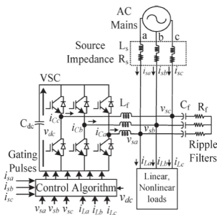
system[2-5]. The execution of DSTATCOM depends upon the exactness of music streams,tuned esteem of interfacing conductors(Lf) are joined at air conditioning yield of the VSC>For all the methods thar are present for suppression of harmonics therer is a common belief that the voltage at the point of common coupling is tightly regulated and cannot be influenced by the currents injected by the shunt device which is connected externally on the distribution system.The DSTATCOM employs an inverter to convert the DC link voltage of adjustable magnitude and phase i.e, to an alternating one.It is basically connected near to the load because we can inject dc components on to the load.So here we are employing inverter which converts DC to AC and viceversa.The schematic diagram of a VSC based DSTATCOM is shown on the below fig which is connected in shunt to the distribution network along with the controller.
Fig. 1. Schematic diagram of VSC-based DSTATCOM.
a balanced voltage at that bus, irrespective of unbalance or distortion on either side of the bus. In this mode, responsibility of the utility is the operation and maintenance of the DSTATCOM effectively.In a voltage control mode, it can make the voltage of the bus to which it is connected a balanced sinusoid, irrespective of the unbalance and distortion in voltage in the supply side or line current.Alternatively, in the current control mode, the DSTATCOM compensates for any unbalance or distortion in the load. Ideally, it should draw a balanced load current from the system, irrespective of any unbalance or harmonics in either the source or load side. Similarly when operated in a current control mode, it can force the source side currents to become balanced sinusoids.It is also assumed that the DSTATCOM is placed at a utility bus on customer.The phase of the output voltage of the thyristor based inverter,Vi,is controlled in the same way as the distribution system voltage Vs.
A DSTATCOM is capable of compensating either bus voltage or line current.
Three load buses. It is assumed that consumers are supplied from these buses. A DSTATCOM can be connected in any of these buses, depending on whether it belongs to the utility or a particular customer. For example, if the voltage at bus 3 is distorted, it affects customers both at buses 3 and 4. The utility may then install a DSTATCOM at this bus to clean up its voltage. On the other hand, suppose that the consumer at bus 4 has loads that draw unbalanced and distorted current from the supply. In order to avoid a penalty, one option for the consumer is to install a DSTATCOM on its premises, so that the current drawn from bus 4 is a balanced.VSCs using PWM controllers are the mainstay of modern power electronics controllers, such as STATCOM, DVR and HVDC-VSC stations. One of the many advantages of VSCs using PWM control is that they can produce quasi-sinusoidal voltage waveforms, having almost any desired phase relationship with an existing AC system waveform, thus dictating the direction and magnitude of the active and reactive power exchanged with the AC system. In practice, the high harmonic frequencies generated by the VSC could be filtered out by high-frequency harmonic
filter [101, but in real time the operation of such filters will not be perfect or they may not even be operating.Moreover, harmonic interactions between the VSC and the electric network will always take place. This interaction may produce harmonic resonances which can only be predicted with realistic models of the VSC and the electric network. Comprehensive models for power converters have been reported in the open literature. In power systems harmonic studies, switching functions have found widespread acceptance in the modeling of converters based on thyristor, where the commutation period of the thyristors has been included in the switching functions. As an extension, switching functions have also been used in the modeling of converters based on GTOs or IGBTs, showing even greater adequacy than in the former application.
III. CONTROL ALGORITHM
contexts, was discovered and rediscovered, until in 1985 it found its way into connectionist AI mainly through the work of the PDP group. It has been one of the most studied and used algorithms for neural networks learning ever since.
A. Estimation of Weighted Value of Average Fundamental Load Active and Reactive Power Components
The back propagation algorithm looks for the minimum of the error function in weight space using the method of gradient descent.This method is not only more general than the usual analytical derivations,which handle only the case of special network topologies,but also much easier to follow. The combination of weights which minimizes the error function is considered to be a solution of the learning problem. Since this method requires computation of the gradient of the error function at each iteration step, we must guarantee the continuity and differentiability of the error function. Obviously we have to use a kind of activation function other than the step function used in perceptrons, because the composite function produced by interconnected perceptrons is discontinuous, and therefore the error function too.
A BP training algorithm is mainly used to estimate the three phase weighted value of load active power current components (wap, wbp, and wcp) and reactive power current components (waq, wbq, and wcq) from the polluted load currents using the feedforward and supervised principle. In this estimation, the input layer for three phases is given as follows
ILap = wo + iLauap + iLbubp + iLcucp (1)
ILbp = wo + iLbubp + iLcucp + iLauap (2)
ILcp = wo + iLcucp + iLauap + iLbubp (3)
where wo is the selected value of the initial weight and uap,ubp, and ucp are the in-phase unit templates.
The In-phase unit templates are estimated using the sensed PCC phase voltages (vsa, vsb, and vsc). It is the relation of the phase voltage and the amplitude of the PCC voltage (vt). The amplitude of sensed PCC voltages is estimated as
.(4)
2 2 2 2
3
The extracted values of ILap, ILbp, and ILcp are passed through a sigmoid function as an activation function, and the output signals (Zap, Zbp, and Zcp)
of the feedforward section are mostly expressed as
Zap = f(ILap) = 1/(1 + e−ILap) (6)
Zbp = f(ILbp) = 1/(1 + e−ILbp) (7)
Zcp = f(ILcp) = 1/(1 + e−ILcp). (8)
The estimated values of Zap, Zbp, and Zcp are fed to a hid- den layer as input signals.Differentiable activation functions the back propagation algorithm looks for the minimum of the error function. The three phase outputs of this layer(Iap1,
Ibp1, and Icp1) before the activation function are expressed as
Iap1= wo1 + wapZap + wbpZbp + wcpZcp (9)
Ibp1 = wo1 + wbpZbp + wcpZcp + wapZap (10)
Icp1 = wo1 + wcpZcp + wapZap + wbpZbp (11) where wo1, wap, wbp, and wcpare the selected value
of the initial weights in the hidden layer and the updated values of three phase weights using the average weighted value (wp) of the active power current component as a feedback signal, respectively. The updated weight of phase “a” active power current components of load current “wap” at the nth sampling instant is expressed as
wap(n) = wp(n) + μ {wp(n) − wap1(n)} f(Iap1)zap(n)
(12)
Similarly, for phase “b” and phase “c,” the updated weighted values of the active power current components of the load current are given as follows
wbp(n)= wp(n)+μ {wp(n)−wbp1(n)} f(Ibp1)zbp(n) (13)
wcp(n)= wp(n)+μ {wp(n)−wcp1(n)} f(Icp1)zcp(n).
(14)
The extracted values of Iap1, Ibp1, and Icp1 are then passed through a sigmoid function which is an activation function for the estimation of the fundamental active components in terms of three phase weights wap1, wbp1, and wcp1 as
wap1 = f(Iap1) = 1/(1 + e−Iap1) (15)
wbp1 = f(Ibp1) = 1/(1 + e−Ibp1) (16)
wcp1 = f(Icp1) = 1/(1 + e−Icp1). (17)
IV. SIMULATION RESULTS AND DISCUSSION
The DSTATCOM performance is depends upon the accurateness of harmonic current detection. For reducing ripple in compensating currents, the tuned values of interfacing inductors (Lf ) are
connected at the output of an ac Voltage Source Converter. A three phase series combination of a resistor (Rf) and capacitor (Cf ) correspond to the
shunt passive ripple filter which is associated at a point of common coupling (PCC) for reducing the high frequency switching noise of the VSC. The currents (iCabc) of DSTATCOM are injected as required compensating currents to cancel the reactive power components and harmonics of the load currents so that loading due to reactive power component/harmonics is reduced on the distribution system.
(i) Performance of DSTATCOM in PFC Mode
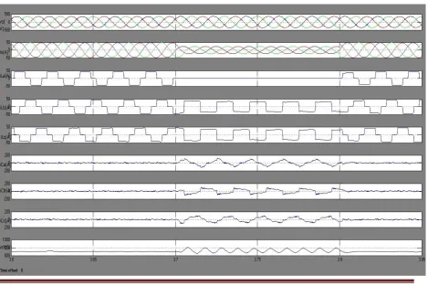
The dynamic execution of a VSC-based DSTATCOM is considered for PFC mode at nonlinear burdens. The execution files are the stage voltages at PCC (versus), adjusted source streams (is), burden ebbs and flows (iLa, iLb, and iLc), compensator ebbs and flows (iCa, iCb, and iCc), and
dc transport voltage (vdc) which are appeared in Fig. under fluctuating burden (at t = 3.7 to 3.8 s) conditions.
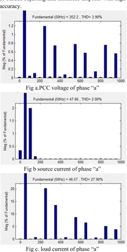
The waveforms of the stage "a" voltage at PCC (vsa), source current (isa), and burden current (iLa) are appeared in Fig3.The total harmonic distortion (THD) of the stage "an" at PCC voltage, source current, and burden current are observed to be 3.90%, 2.00%, and 27.90%, separately. It is watched that the DSTATCOM has the capacity perform the elements of burden adjusting and harmonic disposal with high accuracy.
Fig a.PCC voltage of phase “a”
Fig b source current of phase “a”
Fig c. load current of phase “a”
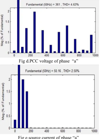
In ZVR mode, the amplitude of the PCC voltage is managed to the reference sufficiency by infusing additional driving receptive force segments. The dynamic execution of DSTATCOM as far as PCC stage voltages (versus), adjusted source streams (is), burden ebbs and flows (iLa, iLb, and iLc), compensator ebbs and flows (iCa, iCb, and iCc), amplitude of voltages at PCC (vt), and dc transport voltage (vdc) waveforms is appeared in Fig. under uneven burden at once span of t = 3.7 to 3.8 s. The consonant spectra of the stage "a" voltage at PCC (vsa), source current (isa), and burden current (iLa) are appeared in Fig.. The THDs of the stage "an" at PCC voltage, source current, load current are seen to be 4.63%, 2.50%, and 28.88%, individually. Three stage PCC voltages are directed up to the appraised esteem. The amplitude of the three stage voltages is controlled from 335.2 to 338.9 V under nonlinear burdens.
Fig d.PCC voltage of phase “a”
Fig e.source current of phase “a”
Fig f. load current of phase “a”
(iii)Performance of UPFC in PFC mode
The dynamic performance of UPFC for PFC mode at non linear loads is shown in the below fig.The performance indices are the phase voltages at PCC(vs),balanced source currents(is),load currents(iLa,iLb,iLc) and compensator currents (iCa,iCb,iCc) and dc bus voltage(vdc) are shown below under varying load durimg the time duration 3.7 to 3.8s.The results are found to be satisfactory when compared to DSTATCOM as there is a visible decrease in the THD which is the main objective of the project.The total harmonic distortion of the phase “a” at PCC voltage is 0.01%,the THD of laod current of phase “a” is observed as 2.57% and finally the THD of source current is found to be 0.86%.
Fig h. Source current of phase a “i
sa”
Fig i.PCC voltage of phase a “v
sa”
Fig 3.Performance of UPFC under nonlinear loads in PFC mode isa, isb,and isc with vab; iLa, iLb, and iLc; and
iCa, iCb, and iCc. Harmonic spectra of isa, iLa, and vab.
The dynamic performance of UPFC is conducted for power factor correction(PFC) mode at non linear loads.The following are the performance indices,the phase voltages at PCC(vs),balanced source currents(is),load currents(iLa,iLb,iLc) and the compensator currents (iCa,iCb,iCc) and the dc bus voltage(vdc) under varying loads during the time period 3.7 to 3.8s.
(v)Performance of UPFC under Zvr mode
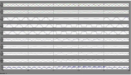
In zvr mode the amplitude of the point of commom coupling (pcc)voltage is regulated to the reference amplitude by injecting extra leading reactive power components.The dynamic performance of UPFC in terms of PCC voltages(vs),balanced source currents(is),load currents(iLa,iLb,iLc),compensator currents(iCa,iCb,iCc),amplitudes of voltages at vt and dc bus voltage(vdc) waveforms are shown in below fig under unbalanced load at a time duration t=3.7 to 3.8s.
Fig. 4 Performance of UPFC under nonlinear loads in ZVR mode: isa, isb,and isc with vab; iLa, iLb, and iLc; and
iCa, iCb, and iCc Harmonic spectra of isa, iLa, and vab.
These results shows satisfactory performance of UPFC for harmonic elimination and load balancing of non linear loads as according to IEEE-519
standard limit there is permissible amount of 5% in errors.
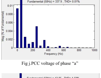
The fig below shows the waveform and harmonic spectra and from these the total harmonic distrortion(THD) is calculated.The results are as follows:The harmonic distortion of the “a” phase source current is observed as 1.59%,the harmonic distortion of load current is observed as 2.34% and the harmonic distortion of PCC voltage is observed as 0.01%.These results shows better performance of the BP algortithm for harmonic elimination.
Fig j.PCC voltage of phase “a”
Fig k.Source current of phase “a”
fig l.Load current of phase “a”
(V) TABLE 1
Performance of DSTATCOM and UPFC
VI.CONCLUSION
This paper presents a comparision between two custom power devices.They are DSTATCOM and UPFC.The comparision is made by using ANN(artificial neural networks).In artificial neural network we are using back propagation control algorithm.The reactive power and unbalnced currents are eliminated by using DSTATCOM.So here compensation of harmonics in distribution systems is carried out.A neural network has been proposed to predict the next step value of the output power on the basis of the values of the control input and output power at preceeding instants.Back Propagation control alogorthm and ILST are the two types of control algorithm that are generally used for the extraction of reference source currents.The thesis mainly concentrated on two important effects of power quality.The first one is the current harmonic and the second one is load voltage harmonics.To design the alternative control schemes for switching of the shunt active power filter artificial neural
Device Mode Performance parameters
Non linear load(rectifier with
R and L load) DSTATCO
M
PFC
ZVR
PCC Voltage SupplyCurrent
Load current PCC Voltage Source current
Load current
352.2V,3.90% 47A.66,2.00% 46.57A,27.90% 361V,4.63%
50.16A,2.50% 46.09A,28.88%
UPFC PFC
ZVR
PCC Voltage SupplyCurrent
Load Current PCC voltage SourceCurrent
Load Current
network and fuzzy logic controllers are used. The various activities that are performed by DSTATCOM are transients elimination and balancing of unbalanced loadsVarious that has been demonstrated in Zero Voltage Regulation and Power Factor Correction modes of DSTATCOM with dc voltage regulation. For the compensation or suppression of harmonics in nonlinear loads the DSTATCOM shows a satisfactory performance which can be seen in the simulation results of DSTATCOM.The performance has been found better for this application because the extracted reference source currents exactly traced out,that means compensated the sensed source currents during the steady state as well as dynamic conditions i.e,under fluctuating conditions of the distribution system.Although the implemented methods provide the distortion levels within the specified IEEE standards(that means 5% of harmonics are allowed)achieving balanced load currents from the unbalanced system was a difficult task which leads to the flow of neutral current.The other problem that we have overcame here is without any overshoots/undershoots we have regulated the DC bus voltage of the DSTATCOM to the rated value.The description of the BP control algorithm is carried out by the simulation results under non linear loads.It can also be
said that a DSTATCOM though it is conceptually similar to a STATCOM at the transmission level,its control scheme should be such that in addition to complete reactive power compensation, power factor correction and total harmonic distortion are also checked.The results are also verified for UPFC.Thus,the two objectives of the thesis were attained by modeling and simulating the neutral compensator and UPFC.Therefore the proposed method made an enhancement in the power quality in the distribution system.
VII.REFERENCES
[1] R. C. Dugan, M. F. McGranaghan, and H. W. Beaty, Electric Power Systems Quality, 2nd ed. New York, NY, USA: McGraw-Hill, 2006.
[2] A. Ortiz, C. Gherasim, M. Manana, C. J. Renedo, L. I. Eguiluz, and R. J. M. Belmans, “Total harmonic distortion decomposition depending on distortion
origin,” IEEE Trans. Power Del., vol. 20, no. 4, pp. 2651–2656, Oct. 2005.
[3] T. L. Lee and S. H. Hu, “Discrete frequency-tuning active filter to suppress harmonic resonances of closed-loop distribution power systems,” IEEE
Trans. Power Electron., vol. 26, no. 1, pp. 137–148,
Jan. 2011. 1212 IEEE TRANSACTIONS ON INDUSTRIAL ELECTRONICS, VOL. 61, NO. 3, MARCH 2014
[4] K. R. Padiyar, FACTS Controllers in Power
Transmission and Distribution. New Delhi, India:
New Age Int., 2008.
[5] IEEE Recommended Practices and Requirement
for Harmonic Control on Electric Power System,
IEEE Std.519, 1992.
[6] T.-L. Lee,S.-H.Hu, and Y.-H. Chan, “DSTATCOM with positive sequence admittance and negative-sequence conductance to mitigate voltage fluctuations in high-level penetration of
distributed generation systems,” IEEE Trans. Ind.
Electron., vol. 60, no. 4, pp. 1417–1428,Apr. 2013.
[7] B. Singh, P. Jayaprakash, and D. P. Kothari, “Power factor correction and power quality improvement in the distribution system,” Elect. India Mag.,pp. 40–48, Apr. 2008.
[8] J.-C. Wu, H. L. Jou, Y. T. Feng, W. P. Hsu, M. S. Huang, and W. J. Hou, “Novel circuit topology for three-phase active power filter,” IEEE Trans.Power Del., vol. 22, no. 1, pp. 444–449, Jan. 2007.
[9] Z. Yao and L. Xiao, “Control of single-phase grid-connected inverters with nonlinear loads,” IEEE
Trans. Ind. Electron., vol. 60, no. 4, pp. 1384–1389,
Apr. 2013.