281 Optimization of Process Parameters on Kerf Width & Taper Angle on En-8 Carbon Steel by Abrasive Water Jet Machining
1
Lakshmigalla Sunil Kumar, 2U.Ashok Kumar,3 P. Laxminarayana
4
P.Vivek Yadav,4T.Sachindra Bhushan, 4P.Saikumar, 4B..Nagaraju
1
Asst.prof, 4UG Student, Department of Mechanical Engineering,NNRESGI, Ghatkesar,India
2
Asst.prof. 3Prof. Mech. Engg., Dept., University College of engineering, Osmania University, Hyderabad
Abstract: Abrasive water jet machining is a process where the material is removed by the principle of erosion. In this paper, the
cutting of EN-8 carbon steel was carried out by AWJM process where the input parameters are water jet pressure, abrasive flow rate and traverse speed, which are taken into consideration machining. kerf width and the kerf taper angle of EN-8 steel are measured with respect to the above-mentioned input parameters using Taguchi L9 orthogonal array Design of Experiments. In this experiment, it has been observed that the main parameter which affects the experimental values is the abrasive flow rate.
Keywords: Kerf Width, Kerf Taper Angle, Taguchi L9 Array.
1.INTRODUCTION
Abrasive water jet machining is a mechanical machining process where the material is removed by the principle of erosion. In this process, a high velocity stream of water jet mixed with abrasive is made to impinge on the target material that is to be machined. Upon the impingement of the high velocity water and abrasive jet the material from the target material is removed. In this process the water from the reservoir is pumped to the intensifier where its pressure increases up to 4 bars. The intensifier increases the pressure of water from 4 bar to about 40000 bars and above as per the requirement. The water from the intensifier is sent to the accumulator where the pressure fluctuations due to high pressures are eliminated. Then the pressurized water from the accumulator is sent to the mixing chamber through control valves. Before entering the nozzle the water is mixed with abrasives particles in mixing chamber in a proportionate ratio. This high pressure of water is converted into kinetic energy of abrasive water jet in nozzle which is made to impinge on the material which is to be machined.
2.WORKINGPRINCIPLE
The Abrasive Jet Machining is a non-traditional machining process involves the application of a high-speed stream of abrasive particles assisted by the pressurized air on to the work surface through a nozzle of small diameter. Material removal takes place by abrading action of abrasive particles. Water jet machining is an erosion process technique in which water under high pressure and velocity precisely cuts through and grinds away minuscule amounts of material. The addition of an abrasive substance greatly
Fig :1 Line Diagram of Abrasive Water jet Machining
3. EXPERIMENTALSETUP
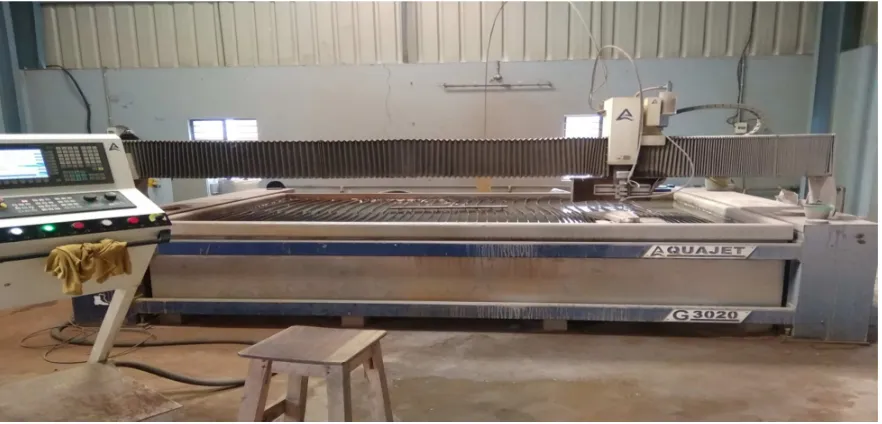
Aquajet abrasive water jet machine G3020 German Engineering was used for the experiment. the input parameters were taken into consideration with respect to
[image:2.612.94.535.383.595.2]previous papers i.e. water jet pressure, traverse speed and abrasive flow rate.
Fig :2. Abrasive Water jet Machining setup used for the Experiment of EN-8
Table:1 Machining Range of parameters of Abrasive Water Jet machine
Condition Range
Water jet pressure(bar) 4000
Abrasive flow rate(gm/min) 700
Traverse speed(mm/min) 1200
Nozzle diameter(mm) 1
283
Water flow rate(liters/min) 4
Abrasive particles(mesh garnet) 80
4. EXPERIMENTALMATERIAL
EN8 carbon steel is a common medium carbon and
medium tensile steel, with improved strength over mild steel, through-hardening medium carbon steel.EN8 steels are generally used in the as supplied untreated condition. and further surface-hardened by induction processes, producing
components with enhanced wear resistance. Material in its heat treated forms possesses good homogenous metallurgical structures, giving consistent machining properties. EN-8 is used in manufacture of general purpose axles, shafts, bolts etc.
Table:2. Shows the Chemical composition of EN-8 steel.
Element Carbon Silicon Manganese phosphorous Sulphur
Composition 0.36 to 0.44% 0.10to 0.40% 0.60to 1.00% 0.050 max 0.050 max
Table:3. Mechanical properties of EN-8 steel.
Property Value
Max stress 700-850 n/mm2
Yield stress 468 n/mm2min
Proof stress 450 n/mm2min
Elongation 16% min
Hardness 201-255 Brinell
5. DESIGNOFEXPERIMENT:
The techniques usually performed in Design Of Experiments to determine the individual and interactive effects of many factors which could affects the results in any design models. The shortest way for this experiment that predicts the outcomes by changing the process parameters which represents by one or more independent variables. Main concepts in the experimental design includes the establishment of validity, reliability, and replicable of the experiments. These concerns may be partially addressed by choosing the independent variables, thus reduction in the risk of measurement errors, and ensuring the documentation of the method is sufficiently
explained in detail. Related concerns includes achieving appropriate level of statistical power and sensitivity is observed and it cannot be manipulated of rewritten without proper concerns.
To achieve a perfect cut, it requires that the combinations of the process variables that gives the jet high enough energy to penetrate through the work piece, which are considered for machining and also for further performances. In present study some
process parameters are water jet pressure, traverse speed and abrasive flow rate were preferred as control factors for the experiment and for obtaining the results.
Table:4.The initial input parameters for AWJM of EN-8 material
Parameter Level-1 Level-2 Level-3
Water jet pressure 3200 3400 3600
Abrasive flow rate 250 350 450
Traverse speed 154 176 220
Table:5.Experimental Design of Taguchi L9 orthogonal array with parameters for AWJM of EN-8 material cutting Levels Water jet pressure Abrasive flow rate Traverse speed
1 3200 250 154
2 3200 350 176
3 3200 450 220
4 3400 250 176
6 3400 450 154
7 3600 250 220
8 3600 350 154
9 3600 450 176
6. EXPERIMENTALOUTCOMES
The outcomes of the experiments are kerf width and kerf taper angle of the material. Kerf width is the width of the
cut made by the abrasive water jet on the target material. it is measured by the formula given below
Kerf width =( )
Where, Top width is the width of the cut on the surface of the material which is facing the abrasive water jet
Bottom width is the width of the cut at bottom surface
Kerf taper angle is the angle subtended by the kerf taper. It is the deviation of the cut from the original cut. Kerf taper angle is given by the formula as given below
Kerf taper angle, Ɵ =tan ( )
Where, L is the length of the cut made by the abrasive water jet
7. RESULTSANDDISCUSSIONS
Table:6 .Results of AWJM of EN-8 material cutting using L9 Taguchi Design of Experiments
Experiments Input Parameters
Outcomes
Water jet pressure Abrasive flow rate Traverse speed Kerf width Kerf Taper angle
1 3200 250 154 0.473 0.046
2 3200 350 176 0.539 0.012
3 3200 450 220 0.492 0.007
4 3400 250 176 0.448 0.065
5 3400 350 220 0.473 0.005
6 3400 450 154 0.636 0.002
7 3600 250 220 0.447 0.002
8 3600 350 154 0.604 0.005
9 3600 450 176 0.600 0.013
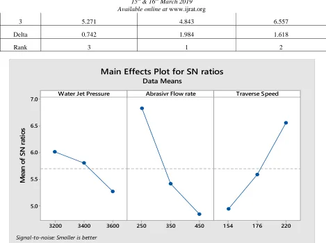
EFFECT OF KERF WIDTH WITH WATER JET PRESSURE,ABRASIVR FLOW RATE,TRAVERSE SPEED
Table:7 . Signal to Noise Ratios of AWJM of EN-8 material
Level Water Jet Pressure Abrasive Flow Rate Traverse Speed
1 6.013 6.827 4.939
285
3 5.271 4.843 6.557
Delta 0.742 1.984 1.618
[image:5.612.73.542.59.409.2]Rank 3 1 2
Fig 3:Signal to Noise Graph Kerf width of EN-8 by AWJM Process
EFFECT OF KERF ANGLE WATER JET PRESSURE,ABRASIVR FLOW RATE,TRAVERSE SPEED
Level Water Jet Pressure Abrasive Flow Rate Traverse Speed
1 36.09 45.21 42.35
2 41.25 43.49 33.29
3 45.91 45.91 47.7
Delta 9.82 10.11 14.41
Rank 3 2 1
3600 3400
3200 7.0
6.5
6.0
5.5
5.0
450 350
250 1 54 1 76 220
Water Jet Pressure
M
e
a
n
o
f
S
N
r
a
ti
o
s
Abrasivr Flow rate Traverse Speed
Main Effects Plot for SN ratios
Data Means
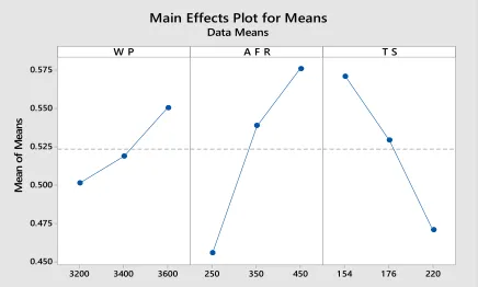
Fig 4: Means Graph Kerf Taper angle of EN-8 by AWJM Process
8. CONCLUSIONS
The present work deals with the abrasive water jet machining of EN-8 Carbon steel materials.the following results were drawn as follows
• The optimum combination for Kerf Width is A1B1C3 ie(water pressure of 3200 bar,
Abrasive flow rate of 250 gm/min, Traverse speed of 220mm/min).
• The optimum combination for Kerf Taper angle is A3B3C3 ie(water pressure of 3620 bar, Abrasive flow rate of 450 gm/min, Traverse speed of 220mm/min)
REFERENCES
[1] U Ashok Kumar, G Ajay Kumar, P Laxminarayana, Influence of Process Parameters on Surface Roughness Of En31 By Water Jet Machining , Proceedings of The International Conference on Technological Advances In Mechanical Engineering (ICTAME 2017) ,Page no.217-221
[2] Chithirai, P. S. M. and S. R. N. Mohanna, Abrasive Waterjet Cutting Surfaces of Ceramics - An Experimental Investigation. International Journal of Applied Science, Technology and Engineering Research, 2012. 1(3): p. 52-59.
[3] L.M. Hlavac, I.M. Hlavacova, L. Gembalova, J. Kalicinsky, S. Fabian, J. Mestanek, J. Kmec, V. Madr, Experimental method investigation of the abrasive water jet cutting quality, Journal of Materials Processing Technology 209 (2009) 6190–6195.
[4] J. Kechagias, G. Petropoulos, N. Vaxevanidis, Application of Taguchi design for quality characterization of abrasive water jet machining
of TRIP sheet steels, Int. J. Adv. Manuf. Technol. 62 (2012) 635–643.
[5] U Ashok Kumar, P. Laxminarayana “Optimization of Electrode Tool Wear in micro holes machining by Die Sinker EDM using Taguchi Approach” Materials today: proceedings 5(1):1824-1831, January 2018, DOI: 10.1016/j.matpr.2017.11.281
[6] U Ashok Kumar, P. Laxminarayana “Study of surface morphology on micro machined surfaces of AISI 316 by Die Sinker EDM” Materials today: proceedings 4(2):1285-1292.
December 2017,
DOI: 10.1016/j.matpr.2017.01.149
[7] U Ashok Kumar, P. Laxminarayana, "Study of Tool Wear Optimization in Micro Holes Machining of SS316 by Die Sinker Electrical Discharge Machining", International Journal of Scientific Research in Multidisciplinary Studies, Vol.3, issue.7, pp.1-4, 2017
[8] U Ashok Kumar, P. Laxminarayana “Optimization of process parameters of Material Removal Rate in Micro hole Machining by Die sinker EDM, IOSR Journal 3600 3400 3200 0.575 0.550 0.525 0.500 0.475 0.450 450 350
250 1 54 1 76 220
W P M e an o f M e a n s
A F R T S
287 of Engineering (p): 2278-8719 Vol. 07, Issue
07 (July. 2017), ||V1|| pp. 61-65
[9] Milan Brozek, “Steel cutting using Abrasive water jet”, Engineering for rural development, Jelgava, 24.-26.05.2017
[10] Natarajan Yuvraj, Murugusen Pradeep Kumar, “Investigation of process parameters influence in Abrasive water jet cutting of D2 steel”, Materials and Manufacturing Processes, 32:2, 151-161,
DOI:10.1080/10426914.2016.1176183
[11] Piotr Loschner, Krzysztof, Poitr Nieslony, “Investigation of the effect of cutting speed on surface quality in Abrasive water jet cutting of 316L stainless steel”, International Conference on Manufacturing Engineering and Materials, ICMEM 2016, Procedia Engineering 149 (2016) 276-282.
[12] Mohammad S.Alsoufi, Dhia K.Suker,
Abdulaziz S.Alsabban, Sufyan Azam, “Experimental study on surface roughness and micro-hardness obtained by cutting Carbon steel with Abrasive water jet and Laser Beam Technologies”, American Journal of Mechanical Engineering, 2016, vol. 4, no.5, 173-181, DOI:10.12691/ajme-4-5-2
[13] R.Kovacevic, “Surface texture in Abrasive water jet cutting”, Journal of Manufacturing systems, volume 10/No.1.
[14] Gaurav D.Sonawane, Radhey M.Bachhav,
“Abrasive water jet machining –A Review”, IOSR Journal of Mechanical and Civil Engineering (IOSR-JMCE), e-ISSN:2278-1684, p-ISSN: 2320-34X, vol:12, issue 4 ver.II (jul.-Aug.2015), PP 44-52.7