A Novel Approach to design and implement
High Speed UART by Using Verilog HDL
A.Raghavendra Reddy1, D.Chinna Babu2, G.Manikanta Chowdary3, S.Mansoor Basha4, H.S.Ijaz5
UG Student [ECE], Dept. of ECE, Santhiram Engineering College, Nandyal, Andhra Pradesh, India1
UG Student [ECE], Dept. of ECE, Santhiram Engineering College, Nandyal, Andhra Pradesh, India2
UG Student [ECE], Dept. of ECE, Santhiram Engineering College, Nandyal, Andhra Pradesh, India3
UG Student [ECE], Dept. of ECE, Santhiram Engineering College, Nandyal, Andhra Pradesh, India4
Assistant Professor, Dept. of ECE, Santhiram Engineering College, Nandyal, Andhra Pradesh, India5
ABSTRACT: The advanced technique for implementation of UART with the help of Verilog description language. UART is a serial communication protocol which allows the full duplex communication in serial link it is an essential to computers and allows them to communicate with low speed peripheral devices, such as the keyboard, the mouse, modems etc., allows the data to communicate with other without synchronization. UART consists of receiver and transmitter module, these modules are having separate pins for inputs and outputs for controlling, so we use UART when the transmitter and receiver data controlling and to increase the accuracy and to avoid the effect of noise and also it provides good speed. Generally it is used to make a interface between rs232 and microcontroller. The main aim of the design and implementation of UART using Verilog HDL is to design universal asynchronous receiver and transmitter using the Verilog HDL.
KEYWORDS: UART, Transmitter, Receiver, Verilog HDL, Xilinx ISE 14.1.
I.INTRODUCTION
Universal Asynchronous Receiver Transmitter is an integrated circuit, which is used for transmitting and receiving data asynchronously via the serial port on the computer. It contains a parallel-to-serial converter for data transmitted from the computer and a serial-to parallel converter for data coming in via the serial line. The UART also has a buffer for temporarily storing data from high-speed transmissions. In addition to the basic job of converting data from parallel to serial for transmission and from serial to parallel on reception, a UART will usually provide additional circuits for signals that can be used to indicate the state of the transmission media and to regulate the flow of data in the event that the remote device is not prepared to accept more data. For example, the device connected to the UART is a modem. UART must have a larger internal buffer to store data coming from the modem until the CPU has time to process it. If the memory buffer used to store the data isn't large enough an overflow might occur. The size of the buffer depends on the design of the UART.
UART provides full-duplex communication in serial link; this has been widely used in the data communications. UART includes a transmitter and a receiver. Transmitter controls transmission by taking a data word in parallel format and directing the UART to transmit it in a serially. Likewise, the Receiver must detect transmission, receive1 the data in serially, and store the data word in a parallel format. The conversion of serial to parallel data is handled by UART. Serial communication reduces the distortion of a signal; therefore data transfer is possible between two systems separated by great distance. The UART serial module is divided into three sub-modules: The baud rate generator, receiver module and transmitter module. The baud rate generator is used to produce a local clock signal. In data transmission through the UART, once the baud-rate has been established, both the transmitter and the receiver’s internal clock are set to the same frequency. TXD is the transmit side, i.e. the output of the UART RXD is the receiver, i.e. the input of the UART. The UART receiver module is used to receive the serial signals at RXD and convert them into parallel data.
Bit the data bits are sent, with the Least Significant Bit (LSB) sent first. The start bit is always low and the stop bit is always high. When the complete data word has been sent, it adds a parity bit this parity bit may be used by the receiver to perform error checking. Then at least one Stop Bit is sent by the transmitter. Because asynchronous data are “self-synchronizing”, if there is no data to transmit, the transmission line will be idle.
II.UART OPERATION
UART exchanges text data in an American standard code for information interchange (ASCII) format in which each alphabetical character is encoded by 7 bits and augmented by a parity bit that can be used for error detection . for transmission ,the modem wraps this 8 bit sub word with a start –bit in the least significant bit (LSB) ,and stop-bit in the most significant bit(MSB) ,resulting in the 10-bit word format shown in figure 1 the first 9 data bits are transmitted in sequences ,beginning with start –bit ,with is bit beingasserted at the serial line for one cycle of the modem clock. The stop –bit may assert for more than one clock.
Fig 1: Data format for ASCII text transmitted by a UART
The UART transmitter is always part of larger environment in which a host processor controls transmission by fetching a data word in parallel format and directing the UART to transmit it in a serial format .likewise, receiver must detect transmission, receive the data in serial format, and strip off start-and stop-bits, and store the data word in a parallel format. The receiver‘s job is more complex, because the clock used to send the inbound data is not available At the remote receiver .the receiver must regenerate the clock locally, using the receiving machines clock rather than the clock of the transmitting machine .The simplified architecture of a UART presented in figure 2 shows the signal used by host processor to control the UART and to move data and from a data bus in the host machine. Details of the host machine are not shown.
Fig 2: Architecture of UART
III.UART TRANSMITTER
(XMT-shiftreg ) , and a status register (bit-count) to count the bits that are transmitted .The status register will be included with in the data path unit.
Fig 3: Interface signals of a state machine controller for a UART transmitter
The ASM chart state machine controlling the transmitter is shown figure 4. The machine as three states : idle, waiting, and sending. When reset-is asserted, the machine a synchronously enters idle, bit-count is flushed ,XMT-shftreg is loaded with 1 s ,and the control signal clear, load-XMT- ,XMT-shftreg , shift ,and start are driven to 0. In idle, if an active edge of clock occurs while load-XMT-data-ref=g is asserted by external host the contents of data-bus while to transfer to XMT-data-reg (this action is not part of ASM chart because it occurs independently of the state of the machine) the machine remains in idle until start is asserted.
Fig 4: ASM chart for the state machine controller for the UART transmitter
When Byte- ready is asserted, Load-XMT-shftreg is asserted and next –state is driven to waiting. The assertion of load-XMT-shftreg indicates that XMT-datareg now contains data that can be transferred to the internal shift register. At the next active edge of clock, with load-XMT-shftreg asserted, three activities occur:
(1) State transfer from idle to waiting,
As the next active edge of clock, with T-byte asserted state enters sending and LSB of XMT-shftreg is set to 0 to signal the start of transmission at the same time shift is driven to 1, and next-state retains the state code corresponding to sending. At sub sequences active edges of clock, with shift asserted state remains in sending and the contents of XMT-shftreg are shifted towards the LSB the machine increments bit-count after each movement of data, and when bit-count reaches 9 clear asserts, indicating that all of bits of augmented word have been shifted to serial output. At the next active edge of the clock, the machine returns to idle
.
IV.UART RECEIVER
The UART receiver has the task of receiving the serial bit stream of data, removing the start-bit, and transferring the data in a parallel format to a storage register connected to the host data bus. The data arrives at a standard bit rate, but it is not necessarily synchronized with the internal clock at the host of the receiver and the transmitter clock is not available to the receiver. This issue of synchronization is resolved by generating a local clock at a higher frequency and using it to sample the receiver data in a manner that preserves the integrity of the data. In the scheme used here, the data, assumed to be in a 10-bit format will be sampled at a rate determined by Sample _clock, which is generated at the receiver‘s host. The cycles of Sample _ clock will be counted to ensure that the data are sampled in the middle of a bit time, as shown in the figure 6 the sampling algorithm must
(1)Verify that a start bit has been received, (2) Generate samples from 8 bits of the data and (3)Load the data on to the local bus.
Although a higher sampling frequency could be used to, the frequency of sample _clock in this example is 8 times the frequency of the bit clock that transmitted the data. This ensures that a slight mis alightment between the leading edge of a cycle of Sample_clock and the arrival of the start-bit will not compromise the sampling scheme ,because the sample will still be taken within the interval of time corresponding of value 0 after the input data goes low. Then three additional samples will be taken to confirm that a valid start –bit has arrived. Thereafter, 8 successive bits will be sampled at approximately the centre of their bit times. Under worst-case conditions of misalignment, the sample is taken a fully cycle of Sample_clock ahead of actual centre of the bit time, which is a tolerable skew.
Fig 5: UART receiver sampling format for clock regeneration
Fig 6: Interface signals of a state-machine controller for the UART receiver
The ASM chart of a state machine controller for the receiver is shown in figure 8 .The machine has three states: idle, starting, and receiving. Transitions between states are synchronized by Sample _ clk . Assertion of an asynchronous active –low reset puts the machine in the idle state. It remains there until Serial _ in is low, and then makes a transition to starting. In starting, the machine samples Serial _ in to determine whether the first bit is a valid start – bit (it must be 0). Depending on the sampled values , inc _ Sample _ counter and clr _ Sample _ counter may be asserted to increment or clear the counter at the next active edge of Sample _ clock. If the next three samples of Serial _ in are 0, the machine concludes that the start – bit is valid and goes to the state receiving. Sample _ counter is cleared on the transition to receiving. In this state, eight successive samples are taken (one for each bit of the byte, at each active edge of Sample _ clk),with inc _Sample _ counter asserted. Then Bit _ counter is incremented. If the sampled bit is not the last (parity) bit , inc _ Bit _ counter and shift are asserted. The assertion of shift will cause the sample value to be loaded into the MSB of RCV _ shftreg, the receiver shift register, and will shift the 7 leftmost bits of the register towards the LSB.
After the last bit has been sampled, the machine will assert read _ not _ ready _ out, a handshake output signal to the processor, and clear the bit counter. At this time, the machine also checks the integrity of the data and the status of the host processor. If read _ not _ ready _in is asserted, the host processor is not ready to receive the data (Error1). If a stop –bit is not the next bit (detected by Serial _ in =0), there is an error in the format of the received data (Error2). Otherwise, load is asserted to cause the contents of the shift register to be transferred as a parallel word to RCV _ datareg, a data register in the host machine, with a direct connection to data _ bus.
The received data word is b5h=1101_01012. The reception sequence is from LSB to MSB, and data move
through the inbound shift register from MSB to LSB. The data word is preceded by a start bit and followed by a stop-bit.with reset_ having a value of 0, the state is idle and the counters are cleared. At the first active edge of Sample_clock after the reset condition is de asserted, with Serial_in having a value of 0, the controller’s state enters starting to determine whether a start bit is being received. Three more samples of Serial_in are taken, and after a total of four samples have been found to be 0, the Sample_counter is cleared and the state enters receiving. After the eighth sample, shift is asserted. The sample at the next active edge of the clock is shifted into the MSB of RCV_shftreg .The value of RCV_shftreg becomes 80h=1000_00002.The sampling cycle repeats again ,and a value of 0 is sampled and
loaded into RCV_shftreg, changing the contents of the register to 0100_00002=40h.
Fig 7: UART Receiver ASM chart
V. SIMULATION RESULTS
UART Transmitter:
When the active edge of clock, with T-byte asserted state enters sending and LSB of XMT-shftreg is set to 0 to signal the start of transmission at the same time shift is driven to 1, and next-state retains the state code corresponding to sending. At sub sequences active edges of clock, with shift asserted state remains in sending and the contents of XMT-shftreg are shifted towards the LSB the machine increments count after each movement of data, and when bit-count reaches 9 clear asserts, indicating that all of bits of augmented word have been shifted to serial output. At the next active edge of the clock, the machine returns to idle
.
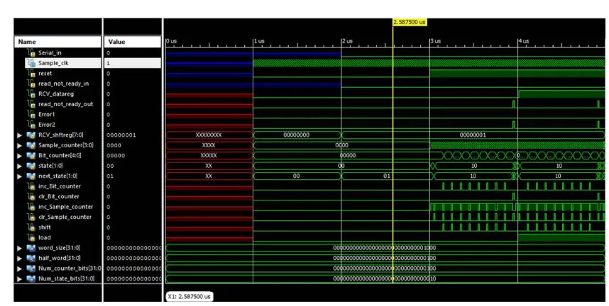
UART Receiver:
Fig 9: when Serial_in=0, read_not_ready_in=0
At the first active edge of Sample_clock after the reset condition is de asserted, with Serial_in having a value of 0, the controller’s state enters starting to determine whether a start bit is being received. Three more samples of Serial_in are taken, and after a total of four samples have been found to be 0, the Sample_counter is cleared and the state enters receiving. After the eighth sample, shift is asserted. The sample at the next active edge of the clock is shifted into the MSB of RCV_shftreg.
VI. APPLICATIONS
UARTs are used for devices including GPS units
Modems
wireless communication
Bluetooth modules, amongst many other applications
low-cost home computers or embedded systems dispense with a UART
VII.CONCLUSION
HDL and this verilog code is simulated using the XILINX ISE 14.1 simulator. The simulation results or waveforms for both the UART transmitter and receiver are obtained.
REFERENCES
[1] Advanced digital design with the verilog HDL,Michael D.Ciletti, TMH,2002.
[2] Naresh Patel, Vatsalkumar Patel, Vikaskumar Patel, ”VHDL Implementation of UART with Status Register”, 2012 IEEE International Conference on Communication Systems and Network Technologies, 2012.
[3] R.W.Hamming, “Error detecting and error correcting codes”, The Bell System Technical journal Vol. XXIX, April 1950, Vol. 2, American Telephone and Telegraph company.
[4] Elmenreich W, Delvai M, "Time-triggered communication with UARTs”, 4thIEEE International Workshop on Factory Communication Systems, 2002, pp. 97- 104, 2002.
[5] Gallo R, Delvai M, Elmenreich W, Steininger A, “Revision and verification of an enhanced UART”, 2004, Proceedings, 2004 IEEE International Workshop on Factory Communication Systems, pp. 315- 318, 22-24, Sept. 2004.