ABSTRACT
SRIDHARAN, SRIRAGHAV. Performance Evaluation of Two Progressive Damage Models for Composite Laminates under High Velocity Projectile Impact. (Under the direction of Dr Mark Pankow).
Finite element numerical simulations of high velocity projectile impact on composite
laminates have been carried out to study the performance two progressive material damage
models in predicting the structural response. The impact loading simulations are performed in
the commercial softwares, ABAQUS and LS-Dyna. MAT 162 was used as a baseline for
material properties since it has been well characterized in the literature for S2 Glass with
SC-15 resin system. An existing constitutive material model capable of progressive damage
modeling was used to describe material behavior of the laminate in the ABAQUS environment.
The material model is implemented as an in-built ABAQUS VUMAT subroutine. Single
element numerical simulations were used to compare and derive an analogy between the
different input deck properties defined for both material models. The methodology of modeling
interlaminar delamination by both input decks are different and simple delamination models
were used to arrive at the correct properties to define this behavior in respective software.
High velocity projectile impact results on the detailed finite element model of the
laminate revealed significant differences in the predicted residual impact velocity of the
projectile. This behavior was attributed to the absence of modeling through thickness failure
mechanisms in ABAQUS to account for the fiber crush behavior. This failure mechanism was
LS-The study also revealed the ability of the surface based cohesive behavior in ABAQUS
to capture the propagation of interlaminar delamination both in-plane and through the
thickness, analogous to the patterns observed in experimental testing of impact on woven
laminates. The corresponding growth in LS-Dyna models using MAT 162 was slower with
time and predominant along the in-plane principal lamina directions as opposed to a uniform
circular delamination pattern observed in ABAQUS predictions. The comparative study
revealed that the MAT 162 damage model in LS-Dyna is better suited to capture the through
thickness material behavior of composite laminates subject to high velocity projectile impact.
Based on these observations, possible areas for future improvement have been summarized.
Additionally, the MAT162 model is applied to simulate low velocity indentation tests
on a 3mm thick, 24 ply unidirectional graphite epoxy laminate. Initial tests revealed a very stiff
material response leading to high contact forces in the model that diverged from experimental
observations. The contact force was observed to be extremely sensitive to the non-physical
hourglass energy. Although showing initial agreement with experimental tests, the contact
force in the simulation diverged as soon as a small notable change in hourglass energy occurred
that caused a rapid decline in the value of the contact forces. The modeling limitation imposed
by MAT162 restricted to only reduced integration solid elements was found to induce a mesh
instability making the model prone to hourglassing which was specifically a challenge in
Performance Evaluation of Two Progressive Damage Models for Composite Laminates under High Velocity Projectile Impact
by
Sriraghav Sridharan
A thesis submitted to the Graduate Faculty of North Carolina State University
in partial fulfillment of the requirements for the degree of
Master of Science
Mechanical Engineering
Raleigh, North Carolina
2017
APPROVED BY:
_______________________________ _______________________________
Dr. Jeffrey Eischen Dr. Scott Ferguson
DEDICATION
BIOGRAPHY
Sriraghav Sridharan was born on 11th February 1992 in Chennai, India. He completed his
undergraduate degree in mechanical engineering in 2014 from MS Ramiah Institute of
Technology (Visvesvaraya Technological University), Bangalore, India.
Sriraghav fostered an interest in composite materials as an undergraduate student actively
involved with a team in college, designing and building RC Airplanes and Unmanned Aerial
Vehicles. He then proceeded to attend North Carolina State University for graduate studies
majoring in mechanical engineering. He joined the Ballistic Loading and Structural Testing
(BLAST) Lab at NC State proceeding to work on his masters thesis under the guidance of Dr
Mark Pankow on finite element modeling of ballistic impact loading on composite structures.
ACKNOWLEDGMENTS
I would like to sincerely thank my adviser, Dr. Mark Pankow for providing me with this
opportunity to pursue research in composite materials. His patience, support and guidance
throughout my masters journey has helped me immensely and enabled me to pursue this
research work. Aside from my masters research, I worked as a graduate research assistant on
an NSF funded project to study effects of local instantaneous heating of composite structures
which has been very interesting and an enjoyable learning experience. I would like to thank
Dr. Mark Pankow for giving me this opportunity.
Thank you to Dr. Jeffrey Eischen and Dr. Scott Ferguson for serving on my thesis defense
committee.
I would like to thank all my lab mates for the help and support. I would like to express my
gratitude to Dr Shreyas Joglekar and Gaurav Dave for all the technical discussions and
guidance concerning my research topic.
Finally, I thank my parents and all my closest friends here and in different parts of the world
TABLE OF CONTENTS
LIST OF TABLES ... vii
LIST OF FIGURES ... viii
1 INTRODUCTION ... 1
1.1 Projectile impact on Composite Materials ... 1
1.2 Research Background ... 2
1.3 Research Objectives ... 7
1.4 Thesis Outline ... 9
2 COMPOSITE THEORY AND NUMERICAL METHODS ... 12
2.1 Fiber reinforced composites ... 12
Unidirectional Composites... 14
Quasi-Isotropic Laminates ... 16
Fabric Composites ... 16
2.2 Failure modes in Fiber reinforced composites ... 18
Fiber Failure modes ... 18
Matrix Failure Modes ... 19
Delamination ... 21
Fiber Crush... 23
Transverse Matrix Cracking ... 23
Strength Based Failure Criteria ... 24
2.3 Overview of impact mechanics and material response ... 26
2.4 Finite Element Implementation ... 27
Explicit Dynamic Simulations ... 29
2.5 Summary ... 31
3 FINITE ELEMENT MODELING OF COMPOSITES IN LS-DYNA ... 32
3.1 Material model description... 32
3.2 MAT162 Input Deck ... 33
Material Coordinate System ... 37
Strain Rate sensitivity ... 37
Fiber tensile/shear failure modes ... 40
Fiber compressive failure modes ... 41
Matrix failure modes ... 43
Delamination mode ... 44
Through thickness Crush mode ... 44
Damage history parameters... 45
3.3 Damage progression model ... 46
3.4 Damage evolution and delamination in MAT162: Single element simulations ... 47
In-plane Tension ... 48
In-plane compression ... 49
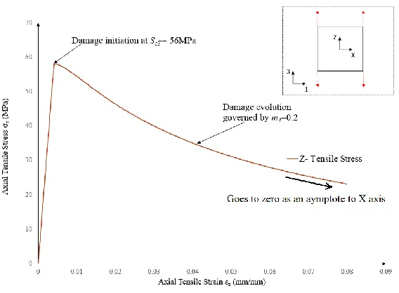
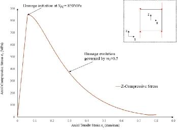
Through-thickness tension along Z-direction ... 51
Effect of damage parameters m ... 53
3.5 Summary ... 58
4 FINITE ELEMENT MODELING OF COMPOSITES IN ABAQUS ... 59
4.1 Material Model Description ... 59
4.2 Elastic damage mechanics model ... 60
Fiber damage ... 60
Shear damage ... 62
4.3 Input deck parameters of ABQ_PLY_FABRIC... 63
Modeling Delamination in ABAQUS ... 68
Damage evolution of cohesive contact behavior ... 71
4.4 Material model implementation in ABAQUS ... 73
Element deletion ... 75
Simple delamination model ... 77
4.5 Summary ... 82
5 RESULTS - HIGH VELOCITY PROJECTILE IMPACT ... 84
5.1 Modeling of ballistic impact ... 85
Modeling aspects in LS-Dyna and ABAQUS ... 90
5.2 Simulation Results... 93
Influence of the Fiber Crush Strength ... 96
Delamination growth and comparison ... 103
5.3 Discussion ... 110
Energy Comparison ... 114
Simulation run time comparison ... 115
5.4 Summary ... 115
6 RESULTS-LOW VELOCITY INDENTER IMPACT ... 117
6.1 MAT 162 Input deck ... 118
Finite element model in ABAQUS ... 119
6.2 Finite element model ... 119
6.3 Simulation Results... 122
Difficulties in Hourglass Control ... 128
Delamination for model with Hourglass Type 4, QM=0.1 ... 130
Delamination for model with Hourglass Type 4, QM=0.001 ... 134
6.4 Summary ... 138
7 CONCLUDING REMARKS ... 140
7.1 Future scope of work ... 142
High Velocity Projectile Impact ... 142
Low Velocity Impact ... 143
REFERENCES ... 144
APPENDICES ... 148
LIST OF TABLES
Table 2.1 In-plane strengths (MPa) for fiber composites Delamination [30] ... 21
Table 3.1 The input elastic properties and lamina strengths to MAT162 material model ... 34
Table 3.2 Damage evolution, element deletion and strain rate parameters provided to MAT162 input deck ... 35
Table 3.3 MAT162 input properties for S2 glass/SC 15 composite panel [1] ... 36
Table 3.4 Experimental tests and methodologies used to determine MAT162 input parameters ... 42
Table 3.5 Damage History variables for UD and fabric lamina [46] ... 45
Table 4.1 Input parameters for ABQ_PLY_FABRIC model in ABAQUS for S2 glass/SC15 ... 65
Table 4.2 Input deck for ABQ_PLY_FABRIC in ABAQUS ... 75
Table 4.3 Element deletion control parameters in ABQ_PLY_FABRIC ... 76
Table 4.4 Properties of cohesive contact behavior between the laminate ... 80
Table 5.1 Key aspects of modeling in LS-Dyna and ABAQUS ... 89
Table 5.2 LS-DYNA and ABAQUS models simulated in this study ... 96
Table 5.3 Percentage differences of DYN0 and DYN1 results from the ABAQUS model ABQ1 ... 100
Table 5.4 Extent of delamination damage initiation for DYN0 and ABQ1 models measured from the center of the model ... 109
Table 5.5 Comparison of simulation run times in the respective solvers for the ABAQUS and LS-Dyna models ... 115
Table 6.1 Material input deck for Graphite-Epoxy IM7/8552 ... 118
Table 6.2 Effect of increase in hourglass energy on the reduction in Contact force (see Figure 6.8) ... 128
LIST OF FIGURES
Figure 2.1 Definition of Orthotropic directions in a lamina [28] ... 13
Figure 2.2 Ply Orientation transformed into global coordinate system [28] ... 15
Figure 2.3 (Left) Unidirectional Lamina and (Right) Woven lamina architecture [33] ... 17
Figure 2.4 Graph comparing fracture toughness of inter-laminar strength of UD and fabrics of different weave patterns of Thornel 3k carbon fiber [32] ... 17
Figure 2.5. Fiber compression failure (Left) and Fiber tensile failure (Right)[28] ... 19
Figure 2.6 Matrix compressive failure (Left) and Matrix tensile failure (Right) [28] ... 20
Figure 2.7 (a) Inter-laminar Delamination [34] (b) Different modes of inter-laminar delamination [35] ... 22
Figure 2.8 Specimen characteristics and loading conditions for (a) DCB test (b) ENF test [35] ... 22
Figure 2.9 Propagation of transverse matrix cracks and their coupling with delamination induced cracks in the 90 degree layer [35] ... 24
Figure 2.10 Front View-0 orientation layer showing the fracture planes during through thickness compressive loading [38] ... 26
Figure 2.11. Typical FE mesh with boundary conditions denoted [42] ... 28
Figure 2.12 Solid elements with 8 nodes [43] ... 29
Figure 3.1 Definition of Material Coordinate system with AOPT=2.0 [43] ... 37
Figure 3.2 X-Tensile stress vs Strain, Corresponding Displacement and boundary conditions applied to element (inset) ... 49
Figure 3.3 X- Compressive stress vs Strain (with SFFC comparison), Displacement and boundary conditions applied to element (inset) ... 50
Figure 3.4 Z- Tensile stress vs strain, Displacement and boundary conditions applied to element (inset) ... 51
Figure 3.5 Z- Compressive stress vs strain, Displacement and boundary conditions applied to element (inset) ... 52
Figure 3.6 Tensile stress-strain relationship for different damage parameters ... 54
Figure 3.7 Finite element model to simulate sphere impact on a [0/90] laminate ... 56
Figure 3.8 Inter-laminar delamination damage during impact at time = 100 micro-seconds (picked nodes encircled and ID’ed ... 56
Figure 3.9 Comparison of delamination damage variables for the picked nodes in the impact zone ... 57
Figure 4.1Schematic of the procedure used to determine input fracture energies for ABQ_PLY_FABRIC ... 66
Figure 4.5 Damage evolution of cohesive contact behavior in ABAQUS ... 72
Figure 4.6 Simple finite element model to study delamination using surface based cohesive behavior (normal loading) ... 77
Figure 4.7 Applied loading on the laminate to induce shear delamination ... 78
Figure 4.8 Comparison of Normal traction stress (Mode I) versus Displacement in ABAQUS and LS-DYNA for the model shown inset ... 79
Figure 4.9 Quadratic Stress Based Damage initiation (CSQUADSCRT) in Normal (Left) and Shear (Right) loading ... 80
Figure 4.10 Damage Initiation and evolution of delamination for normal loading mode (inset) ... 82
Figure 5.1Partitioned faces of the lamina with geometric features on which element sizing is applied ... 86
Figure 5.2 Finite element mesh of each ply with a magnified view of elements in the impact zone ... 87
Figure 5.3 Mesh used for Top cover and Bottom support plates (thickness shown in side view) ... 88
Figure 5.4 Projectile Mesh ... 88
Figure 5.5 Finite element model representing the laminate, projectile and fixture plates (Each lamina is represented as a separate color) ... 93
Figure 5.6 Comparison of projectile velocity in LS-DYNA model with baseline [Gama] results (Impact velocity = 380 m/s) ... 94
Figure 5.7 Comparison of the projectile velocity in ABAQUS model (ABQ1) and baseline LS-DYNA model (DYN0) ... 95
Figure 5.8 Comparison of projectile velocity over time for the different models run in ABAQUS and LS-DYNA ... 98
Figure 5.9 Kinetic Energy time history comparison for DYN0, DYN1 and ABQ1 models .. 99
Figure 5.10 Deformation of laminate and projectile states for DYN0, DYN1 and ABQ1 models (zoomed in to the center site of impact)... 101
Figure 5.11 Cross-section Projectile state and laminate deformation for the three models at 50 μs ... 101
Figure 5.12 Cross-section of Projectile state and laminate deformation for the three models at 100 μs ... 102
Figure 5.13 Cross-section of Projectile state and laminate deformation for the three models at 200 μs ... 102
Figure 5.14 Comparison of delamination initiation at 20 μs f for a) Baseline paper [9] b) DYN0 model c) ABQ1 model ... 105
Figure 5.15 Delamination initiation front for a) DYN0 b) ABQ1 at 50 μs ... 105
Figure 5.16 Delamination initiation front for a) DYN0 b) ABQ1 at 100 μs ... 106
Figure 5.17 Delamination initiation front for a) DYN0 b) ABQ1 at 200 μs ... 106
Figure 5.19 Final delamination shown for a) DYN0 b) ABQ1 and c) experimentally observed
delamination pattern in specimen [9] (visual comparison only-not for data comparison) ... 107
Figure 5.20 Extent of maximum delamination observed at 500 us for a) 10th layer in DYN0 b) 12th layer in ABQ1 (Top view) ... 108
Figure 5.21 Hatched portion is the delamination area traced from Interface 8 (8th and 9th ply) with the frontal area of the projectile subtracted ... 110
Figure 5.22 Cross-shaped delamination pattern dominant in the fiber directions shown for 16 μs and 95 for a) Baseline paper [9] with velocity 360m/s and b) DYN0 model with velocity 380m/s ... 112
Figure 5.23 Back-face delamination on the last ply interface reported in a) Light inspection results by Yen [38] b) Jared Newton [52] c) ABQ1 model in the current study ... 113
Figure 5.24 Comparison of total and hourglass energies for ABQ1 and DYN1 models ... 114
Figure 6.1 Experimental Test setup for Low Velocity Impact test [53] ... 117
Figure 6.2 Partitioned ply geometry and resultant finite element mesh ... 120
Figure 6.3 The finite element mesh of the complete LVI model (layers highlighted with different colors) ... 120
Figure 6.4 Top view of the laminate. The black shaded region is half inch thick (in-plane) over which a 5MPa pressure is applied. ... 121
Figure 6.5 Contact force vs time for experiment and numerical simulation cases (varying hourglass) ... 124
Figure 6.6 Contact force vs indenter displacement for experiment and simulation cases (varying hourglass) ... 124
Figure 6.7 Hourglass energy comparison for different types in LS-Dyna used for the simulation ... 126
Figure 6.8 Mapping the rise in Hourglass energy with drop in Contact force for the different Hourglass types ... 126
Figure 6.9 Internal and Hourglass energies for the different formulations of Hourglass used (Ratio of hourglass energy to the total internal energy is shown inset) ... 127
Figure 6.10 Comparison of projected delamination areas between a) Simulation results reported by Joglekar et.al [58] b) Simulation results in current study ... 131
Figure 6.11 Delamination comparison between the a) LS-Dyna model with Type 4 QM=0.1 hourglass and b) ABAQUS simulation results [53] shown at peak contact force in respective models for the first four ply interfaces. ... 132
Figure 6.12 Delamination comparison between the a) LS-Dyna model with Type 4 QM=0.1 hourglass and b) ABAQUS simulation results [53] shown at peak contact force in respective models for the last four ply interfaces. ... 133
Figure 6.13 Delamination in the top 4 plies of the laminate in a) LS-Dyna b) ABAQUS [53] models at time 1ms (Red areas indicate the onset or initiation of delamination) ... 136
1 INTRODUCTION
1.1 Projectile impact on Composite Materials
Composite materials have been used extensively in defense, automotive and aerospace
applications attributed to their high stiffness and low weight. In these applications, they play a
key role in absorbing the energy against impact loading. An impact event could range from a
dropped tool, travelling at a low velocities (<10m/s), to high speed projectiles travelling at a
few hundred meters per second. The structural response of the composite can be very different
in these two scenarios, from minor damage to complete penetration of the composite.
Low velocity impact tests do not involve penetration of the composite structure
however, the time of contact between the projectile and target is relatively long. This allows
the composite target to absorb and dissipate the kinetic energy over a wider area. The typical
damage mechanisms in this case would be delamination, fiber tensile failure and matrix
cracking [1]. In addition, the composite might also contain Barely Visible Impact Damage
(BVID) which can reduce its residual in-plane strength. High velocity impact events are
penetrative in nature and are dominated by stress wave propagation through the material [2]
that causes highly localized damage in the structure with a clearly visible hole as a result of
perforation. Due to the many failure mechanisms, both global and local, the dynamic structural
response of the composite structure can be very complex involving petal formation of debris,
There is a fair amount of work in the literature that deal with experimental impact
testing on composite specimens for both low and high projectile velocities. Experimental
testing can provide response data only for the particular specimen and loading case. Multiple
experimental tests may be required to characterize the effects of a wide range of variables on
the response of a composite specimen. This may not always be practical in terms of time and
monetary expense. Furthermore, experimental methods need X-Ray and photography
techniques to visually discern the extent of BVID mechanisms.
Finite Element Analysis (FEA) techniques can be a very powerful tool that can simulate
the progressive damage/failure in the composite structure subject to impact loading. It is also
practically feasible to apply FEA techniques to different shapes, orientations of the target
specimens as well as study the effects of varying impact loads and boundary conditions. A
large number of material properties and parameters can be configured into a Finite Element
Model (FEM) that can be used to track the initiation and evolution of various damage modes
in the composite structure. This is particularly desirable if it is required to capture the physics
of the evolution of BVID mechanisms like delamination. Explicit codes available in
commercial FEA packages enable tracking of damage evolution as a function of time as the
impact event occurs. It is also possible to determine the residual velocity of projectiles and
track the ejected debris.
1.2 Research Background
the case of impact loading, the projectile velocity can either be low or high which influences
the extent of damage exerted in the target material. In low velocity impact problems, the
projectile (or indenter) does not perforate the laminate material however, the composite can
fail in a wide variety of Barely Visible Impact Damage (BVID) modes that reduces the
structural strength of the laminate. High velocity impact events involve complete perforation
of the projectile through the laminate and the damage is highly localized to the impact zone.
Low velocity impact tests are performed using standard tests such as Instrumented
Falling Weight Impact testing (IFWIT), Charpy tests etc., which involve impact velocities up
to 10 m/s [4]. Impact force as a function of indenter displacement can be measured from low
velocity impact tests and finite element models can be developed accordingly to capture the
same response. High velocity impact response of composite structures have to be determined
using ballistic experiments involving a gas gun that can fire projectiles at the required velocity
[2], [5]. The damage mechanisms involve spalling and petalling of the laminate from the
backward end with plug formation.
Damage in composites is characterized by formation and evolution of micro-cracks
which are essentially material and surface discontinuities. These irreversible discontinuities in
the laminate will cause stiffness degradation in the laminate [6]. Matzenmiller et. al. explained
the different failure modes of unidirectional laminae such as fiber rupture, fiber kinking ,
matrix cracking and crushing. The Hashin failure criteria [7] is used for damage initiation and
a continuum damage modeling approach is used to exponentially degrade the stiffness based
concept has been used by many researchers [8]–[10] to develop damage models that degrade
the laminate stiffness in a uniform manner based on the nature of loading on the composite
laminate. For example, Vaziri et al. developed an in-plane continuum damage model based on
the work of Matzenmiller et. al. to model impact on unidirectional laminates to determine the
force-time response. This is a plane stress model that does not account for through thickness
properties and delamination in the laminate.
MAT162 is a three-dimensional progressive damage model for unidirectional and woven
(plain-weave) composites that has been developed based on existing orthotropic composite
models in LS-Dyna [11]. The model accepts elastic constants, material strengths and damage
evolution parameters to successfully characterize the initiation, evolution and propagation of
failure modes in composite laminates. While the in-plane elastic moduli and strengths input to
the model can be determined for the composite material using standard ASTM test, the damage
parameters have to be determined from non-standard experimental and numerical simulation
techniques. Researchers who have developed this model have performed a battery of tests to
determine through thickness and damage evolution parameters for MAT162 such as high strain
rate Hopkinson bar tests, low velocity impact and depth of penetration experiments [12] and
Quasi-static punch shear tests [1]. MAT 162 was found to give results matching experimental
observations for both low and high velocity projectile impact problems. Gama et. al. [9] used
MAT 162 to model S2 glass/SC 15 plain weave laminates for projectile impact testing in the
MAT 162 has been used again by Jordan et.al. [12] to model low velocity impact on
plain woven E-glass laminates of different thicknesses and comparing the contact force-time
and force-displacement histories with experiment. Considerable research work has been
undertaken in using ABAQUS modeling for low velocity impact tests in unidirectional
composite laminates [13], [14], [15]. Maio et. al. studied the effect of the delamination damage
parameter in MAT 162 on predicting the extent of delamination in thin (1mm) unidirectional
carbon fiber laminates. They also pointed out the need for hourglass control to accurately
model composites under low velocity impact.
In the current study, it is of interest to model high velocity projectile impact in ABAQUS
and use the results to compare that obtained for the same problem in LS-Dyna. The primary
aim is to focus on material models that are capable of capturing the physics of high velocity
impact problems through progressive damage modeling techniques involving reduction of
strengths and stiffnesses upon the initiation of damage. Most of the damage models that are
used to predict composite behavior in high velocity impact is implemented as custom
subroutines developed by the researchers for the respective material and loading cases
described in their work. Puente et. al. [16] used an extension of the Chang-Chang model [17]
to characterize lamina failure based on a failure stress damage initiation criteria. The through
thickness stresses in tension and shear were used to determine delamination damage initiation.
A user sub-routine was developed by the authors to implement the constitutive relations and
apply it to study impact of a rigid sphere on a woven carbon fiber laminate. Ivanez et. al.[18]
criteria to write a subroutine to simulate high velocity projectile impact response of foam cored
laminates.
Johnson et al. developed a computational method for predicting damage in composite
structures using the work of Ladveze et. al.[20] as framework. This uses a continuum damage
mechanics approach to degrade the in-plane stiffnesses in the fiber directions and an in-plane
plastic strain component to determine the matrix damage in shear. The through thickness
direction is used to model delamination. While implementation of Chang-Chang or Hou
damage models in ABAQUS requires user defined subroutines to be written from scratch, the
damage model based on the work of Johnson et.al. is already built-in to the ABAQUS package
and can be implemented directly as a VUMAT user-subroutine. This subroutine called
ABQ_PLY_FABRIC is a VUMAT for Fabric Reinforced Composites that can only be applied
to two dimensional or plane stress elements [21]. The through thickness damage mechanisms
namely delamination can be modeled using a cohesive based inter-ply surface behavior [22],
[23].
The ABQ_PLY_FABRIC VUMAT has not been used considerably in literature.
Bodepati et. al. used the model to simulate high velocity lead bullet impact on E-glass
composite laminate and obtained residual velocities that were close to experimentally
determined values for the lead bullet. In the current study, ABQ_PLY_FABRIC VUMAT is
employed to define the in-plane laminate material properties and a cohesive based surface
1.3 Research Objectives
The current body of work focuses on the methodology of modeling composite laminates
for capturing damage and failure in impact loading scenarios in different finite element analysis
software. Each software uses different material models and damage evaluation methods for
virtually simulating the impact problem. The MAT162 model in LS-Dyna is developed such
that the input deck material properties and damage parameters are specifically tailored to
capture the structural response of composite laminates to impact loading. The model is reported
to be capable of accurately capturing both in-plane and through thickness damage mechanics,
with good agreement to experimental observations. It has been used to study high velocity
projectile impact events. Researchers who have developed the material model for LS-Dyna
have conducted many experimental tests and numerical simulations to measure and calibrate
the various damage parameters available in the model [1], [24], [25]. MAT162 is a progressive
damage analysis model that involves degradation of laminate stiffness due to onset of particular
mode of damage. The extent of failure in the different damage modes modeled by MAT162
governs the overall response of the composite during impact loading.
The main objectives of the current research study can be summarized in the following points
1) To understand how MAT162 in LS-Dyna is capable of predicting the residual
projectile velocity with good agreement to experimental observations when applied
to simulate high velocity impact on woven fabric laminate by comparing its
2) Identify important additional parameters available in LS-Dyna that is found to
influence the laminate response greatly and is necessary to be defined in order to
capture the impact induced damage mechanisms.
3) Study the extent of induced delamination growth in the laminate as a result of
projectile perforation and explain the differences in delamination observed in both
the models.
The first step to achieve the set objectives is understanding the input deck parameters of
MAT162 model in LS-Dyna using single element numerical simulations to observe the effects
of the input strength and damage parameters. Following this step would be using the built-in
fabric composite progressive damage model ABQ_PLY_FABRIC in ABAQUS to setup the
input deck and compare single element numerical simulations for different loading cases with
that performed in LS-Dyna. Matching these results in the two software will help in building an
analogy between the sets of parameters used in the two material models. With a fundamental
understanding of the input decks derived from single element simulation comparisons in both
software, a larger comprehensive model with exact projectile and laminate geometry can be
constructed to simulate high velocity impact. Comparing the results obtained from both
software, it is possible to draw conclusions about the important parameters in the material
model that influence the extent of damage in the laminate.
Additionally, this research examines the structural response of thick laminates (~25 mm)
delamination of unidirectional composite laminates in LS-Dyna using MAT162. The study is
used to show how close the LS-Dyna model is able to match the observed experimental results.
1.4 Thesis Outline
The second chapter will introduce the reader to Composite materials theory. The basic
stress-strain relationships of material properties are explained. The focus of the chapter is
elucidating the different failure modes occurring in unidirectional and fabric composites
subject to projectile impact. Different failure mechanisms in the in-plane and through thickness
directions act depending on the velocity of impact. The general finite element implementation
of projectile impact modeling using explicit dynamics simulation is discussed.
Following the characterization of laminate failures and introducing the basics of finite
element implementation, the modeling aspects in the LS-Dyna software are explained in
Chapter 3. This chapter introduces the reader to the composites damage material model
MAT162 that is implemented in LS-Dyna specifically to model projectile impact on composite
laminates. The material input deck parameters and failure modeling are explained and the
effects of certain key parameters that characterize the progressive damage in the laminate are
discussed using simple single element numerical simulations. The laminate is made up of S2
glass/SC 15 material.
The reader is introduced to the various aspects of modeling composites in the ABAQUS
software in Chapter 4. This chapter explains the built-in VUMAT subroutine
ABQ_PLY_FABRIC that is used for progressive damage modeling for fabric composites.
material model, single element simulations for different loading cases are presented. These
results were compared with the simulations performed in LS-Dyna to obtain convergence on a
single element level. The single element numerical simulations and delamination comparison
using simple models in both software will be the basis to setup larger models explained in the
following chapters and investigate the difference in results.
Chapter 5 presents the numerical simulation results of high velocity projectile impact on
the S2 glass/ SC15 laminate in both LS-Dyna and ABAQUS. The geometric aspects of the
model and the meshing strategies used in both software are explained. The results for a
particular impact velocity case is first obtained in LS-Dyna using the MAT 162 input deck
which matches the experimental/simulation results in the reference paper [9], thereby
establishing a baseline model for comparison. The results of simulations in ABAQUS using
ABQ_PLY_FABRIC are compared against this baseline model. This type of testing revealed
the importance of through thickness strength parameters that influence the penetration
resistance of the laminate. Certain input deck modifications performed on the MAT162 input
deck led to the finite element results comparing well in both software. The ability of both
software to replicate the delamination zone upon projectile impact was also compared and
studied.
In the sixth chapter, a Low Velocity Impact test (LVI) is simulated for a thick
Unidirectional Carbon fiber laminate (24 plies). The LVI test consists of a rigid hemispherical
simulations are compared against the corresponding experimental results. The testing revealed
2 COMPOSITE THEORY AND NUMERICAL METHODS
The following section is intended to provide the reader with a basic overview of fiber-
reinforced composite theory and typical modes of failure observed. In addition, the formulation
of a time-based analytical finite element model to simulate projectile impact on composites is
discussed.
2.1 Fiber reinforced composites
A composite material is one in which two or more materials are combined on a
macroscopic scale to form a third material. A well-designed composite exhibits the best
qualities of the individual constituents and some unique qualities that neither constituent might
possess [27]. The current study focuses on Fiber Reinforced Composites (FRC) materials.
FRCs are composed of long fibers embedded in a polymer matrix. The fibers are the principal
reinforcement and load bearing member while the matrix supports the fibers and ensures
distribution of the applied loads. A flat arrangement of multiple unidirectional or woven fibers
in a matrix forms a lamina. A lamina is the most basic building block of a laminate, that is to
say, several laminae may be stacked one upon the other to form a composite laminate. The
typical behavior of composites is generally anisotropic, that is, the material properties
(stiffness, toughness, strengths etc.) differ in different directions. However, layered laminates
can be generalized as transversely orthotropic in nature where material properties in three
direction is taken as the principal material direction denoted by ‘1’. The in-plane transverse
direction is denoted by ‘2’. The out-of-plane direction is denoted by ‘3’.
Figure 2.1 Definition of Orthotropic directions in a lamina [28]
For an orthotropic composite lamina, the stress-strain relations can be expressed using
engineering constants with the following equation.
31 21
1 2 3
32 12
1 1 2 3 1
2 13 23 2
3 1 2 3 3
4 4 23 5 5 6 6 13 12 1
0 0 0
1
0 0 0
1
0 0 0
1
0 0 0 0 0
1
0 0 0 0 0
1
0 0 0 0 0
E E E
E E E
E E E
G G G (2.1)
The longitudinal strains εij and shear strains γk are related to the longitudinal stresses σij
(where k=4,5 & 6, representing shear in 23,13 and 12 planes respectively) by the Compliance
matrix that consists of elastic material properties. Ei(i = 1, 2 & 3) represents the Young’s
modulus of the composite in the principal directions. Gijwhere i,j = 1,2; 2,3 and 3,1 represent
the shear modulus of the lamina in the in-plane and out-of-plane transverse directions
respectively. Finally, υijrepresent the Poisson’s ratios.
Unidirectional Composites
Unidirectional composites have all the fibers of the laminae oriented in the same
direction. The fiber direction in each ply is taken as the principal material direction of that ply.
The overall stiffness of a ply along the fiber direction is significantly higher than that in the
in-plane transverse direction which is dominated by the properties of the matrix. For example,
Hexply IM-8552 carbon fiber unidirectional lamina [29] has a longitudinal stiffness of 171
GPa which is almost 19 times its transverse stiffness of 9.08 GPa.
When unidirectional plies of different fiber direction (orientation) are stacked on top of
each other, the individual contributions of each ply can be transformed to a global coordinate
system. By selecting the stacking sequence and orientation of the constituent plies, it is possible
Figure 2.2 Ply Orientation transformed into global coordinate system [28]
As the lamina principal axes (1,2) do not coincide with the loading axes (x,y). The
in-plane stress and strain components referred to the principal material axes can be expressed in
terms of the loading axes (x,y) using the following transformation relation as shown in
Equation (2.2)
1 2 12 x y xy T (2.2)where [T] is the Transformation Matrix given by
2 2 2 2 2 2 2 2m n mn
T n m mn
mn mn m n
(2.3)
Quasi-Isotropic Laminates
The term quasi-isotropic laminate is used to describe laminates that possess isotropic
extensional stiffnesses in the plane of the laminate. That is, on a global coordinate system, the
laminate possesses the same stiffness in all in-plane directions. Quasi-isotropy can be achieved
by having unidirectional plies stacked in a particular sequence. A simplest example can be a
four-layer laminate with the stacking sequence denoted by [0/-45/45/90]. This notation
indicates that there are 4 individual plies of orientation 0◦, -45◦, 45◦ and 90◦ stacked in that order.
Fabric Composites
Fabric composites are made of two inter-laced fibers in the same plane known as warp
and weft (fill) threads that are mutually orthogonal to each other as shown in Figure 2.3. They
are also called textile woven composites. The warp and fill fibers can be interlaced with each
other in different ways to form varieties of weaves like plain, twill or stain [31]. The in-plane
longitudinal and transverse extensional stiffnesses are almost identical. In comparison with
unidirectional composites, the inter-laminar fracture toughness of woven composites is higher
[32]. Kim et. al. attributed the high inter-laminar toughness of woven composites to the effect
of yarn orientation that causes discontinuous cracks and prevents crack propagation and the
Figure 2.3 (Left) Unidirectional Lamina and (Right) Woven lamina architecture [33]
Figure 2.4 Graph comparing fracture toughness of inter-laminar strength of UD and fabrics of different weave
2.2 Failure modes in Fiber reinforced composites
As discussed in the earlier subsections, a composite (unidirectional or woven) is
essentially a combination of fibers bonded together on a polymer matrix. The basic unit (ply)
of a laminate may be loaded in any of the six stress components shown in Equation(2.1).
Stresses and strains act throughout the volume of the composite ply and are determined as
defined volume averages [33]. The six components of stress σij and strains εij are integrated
over the volume of the ply V
1
( , , )
ij ij V
x y z dV V
(2.4)1
( , , )
ij ij V
x y z dV V
(2.5)Average mechanical failure strength can be defined for every component. Each of the
constituents of the composite can fail under application of an external load that exceeds the
stress in the ply beyond the strength. The failure modes can act in-plane or through the
thickness of a composite ply.
Fiber Failure modes
Figure 2.5 shows a schematic of how fibers may fail under tensile and compressive
loading. Under tensile loading a number of fiber breaks occur in the vicinity of each other
direction) will fail when the ultimate stress reaches the critical limit. This limit will be the
tensile or compressive strength of the fibers in the respective mode of loading.
Figure 2.5. Fiber compression failure (Left) and Fiber tensile failure (Right)[28]
Stress-strain relationship pre-failure is fairly linear under longitudinal compressive
loading. Compressive failure is associated with micro-buckling of fibers within the matrix.
Flexural stresses in the fiber caused due to buckling will result in kink zones that give rise to
failure planes. A compressive strength of the lamina is not only influenced by the compressive
strength of the constituents but also by the elastic stiffness and shear strength of the matrix [6].
Matrix Failure Modes
The matrix material can fail in tension or compression based on the nature of loading
in the direction perpendicular to the fibers σ2. For unidirectional composites, transverse tensile
failure is very critical [30] resulting in high stress and strain concentrations. The fracture plane
in transverse tensile loading is perpendicular to the loading direction. In transverse
compression, a unidirectional composite may fail due to a crack at an angle to the loading
Figure 2.6 Matrix compressive failure (Left) and Matrix tensile failure (Right) [28]
Woven composites loaded σ1 and σ2 have similar tensile and compressive strengths
failing predominantly due to fiber breakage as per mechanisms shown in Figure 2.5.The
in-plane shear strength which is a matrix dominated property will be comparatively lower.
1 T
X
andX
2T denote the in-plane tensile strength of the lamina in the directions ‘1’and ‘2’ respectively ,while the compressive strengths are denoted by 1C
X
andX
2C .S
12 willbe the in-plane shear strength. Table 2.1 gives the reader an idea of the typical in-plane
Table 2.1 In-plane strengths (MPa) for fiber composites Delamination [30]
Composite T
1
X
X
1CX
T2X
C2S
12Carbon/Epoxy 2280 1725 57 228 76
Woven Carbon Fabric 963 900 856 900 71
E-glass/epoxy 1140 620 39 128 89
Woven glass/epoxy 367 549 367 549 97.1
Delamination
Delamination is a through thickness failure form of the laminate. It is an interfacial
failure characterized by fiber pullout from the surrounding matrix. Delamination usually
occurs in the interface between plies of different fiber orientations [22]. Interlaminar strength
reduces when composite structures are subject to impact and thereby lead to catastrophic
failure. Delamination behavior can be Mode I (pure tensile separation) or mixed Mode I/II (II
refers to shear induced separation) as shown in Figure 2.7 (b). Numerous experimental tests
and numerical techniques are utilized to characterize and evaluate the extent of interlaminar
Figure 2.7 (a) Inter-laminar Delamination [34] (b) Different modes of inter-laminar delamination [35]
The critical energy release rate characterizes the amount of energy necessary for
inter-laminar fracture in a particular mode. Mode I is characterized by the standardized Double
Cantilever Beam test shown in Figure 2.8 (a) and Mode II energy release rate is determined
from the End Notch Flexure test [35]. The energy release rate in both tests is determined from
a measured applied load P , displacement δand an initial crack length a as it propagates under the influence of load.
In all practical scenarios, the delamination failure is mostly mixed mode i.e. a
combination of Mode I and II [35].
Fiber Crush
Composites are good at absorbing energy during a constant crush load through various
energy absorbing mechanisms [28]. Transverse impact on a composite material can cause high
compressive stresses in the impact zone leading to crush damage. Yen et. al. observed that
through the thickness impact loading causes very high normal stresses in the direction
orthogonal to the layer surfaces. This can result in shear failure along weak material planes.
Hence, compressive loading of a composite can result in both crush failure and transverse
failure of the fibers. Anderrson et. al. noted buckling and kink band formation at the onset of
fiber crush. This is followed by progressive formation of several inter and intra-laminar
transverse cracks leading to splitting of fibers.
Transverse Matrix Cracking
This is an inter-laminar fracture mode caused due to flexing of in-plane fibers to
transverse impact loading [35]. This can be observed in [0/90] layers. Transverse matrix
cracking can couple with matrix cracks caused due to delamination. As damage accumulates,
Figure 2.9 Propagation of transverse matrix cracks and their coupling with delamination induced cracks in the
90 degree layer [35]
Strength Based Failure Criteria
Many theories have been described and documented to analyze failure in composite
materials. Non-interactive theories compare individual lamina stresses or strains with
corresponding strength or limits (maximum stress/maximum strain). There is no interaction
among the different stress components [30]. Interactive theories like Tsai Hill or Tsai Wu club
stress components of into one expression. In this case only the overall failure is predicted and
it is not possible to isolate the cause of failure to a particular mode.
Hashin [7] established a failure criteria based on individual failure mechanisms of fiber
and matrix. Thus, under in-plane loading the failure of a lamina can be classified into two
2 2 2 12
2 12 1
X S
(2.7)
The Hashin failure criteria however does not seem to fit experimental results in the case
of matrix or fiber compression [36]. The failure criteria has been modified to include the effect
of transverse compressive normal stress on the matrix shear strength by Sun, et al [37].
Additional failure components are characterized along fracture planes which in case of matrix
tension are normal to the plane of the plies and parallel to the fiber direction. In matrix
compression the fracture planes are at an angle to the plane of the ply. Davila et.al. proposed
calculation of the angle of fracture plane based on Mohr Couloumb (M-C) effective stresses.
The implementation of M-C criterion for matrix failure is observed to improve the accuracy of
Hashin matrix failure criterion [38].
The M-C criterion has also been generalized to model the through thickness failure of
a composite lamina under compression. This mode of failure is very different from tensile
loading. Based on the Lateral Constrained Compression Test (LCCT) methodology described
by Yen [38], it is possible to measure the fiber crush strength SFC which is analogous to
compressive strength in the through thickness direction. Compressing the composite specimen
through its thickness also initiates cutting of fibers along preferred fracture planes. This is
characterized by the fiber mode shear strength SNFS. The angle of the shear sliding plane θ is
determined from the expression as follows
0.5
sin 2
NFS FC
Figure 2.10 Front View-0 orientation layer showing the fracture planes during through thickness compressive
loading [38]
2.3 Overview of impact mechanics and material response
Impact and collision events give rise to an area of contact between the interacting
bodies. For the period of time the bodies are in contact, the pressure in the contact area results
in local deformation and consequent indentation [39]. The contact pressure at the interface will
give rise to a reaction force exerted in opposite directions that acts on the interacting bodies.
This reaction force referred to as the interaction force ensures that there is no interpenetration
of the interacting bodies.
The current study analyzes transverse impact of a rigid/semi-rigid projectile on a
flexible composite laminate. In the case of low velocity impact, the flexible composite suffers
bending due to interface pressure at the contact zone. The kinetic energy imparted to the
projectile (indenter) is recovered as elastic strain energy in the target laminate. This reduces
As the velocity of the projectile, increases, there reaches a point when its kinetic energy
exceeds the elastic strain energy of the target material. In this scenario, the target can no longer
offer any effective resistance to the projectile at the onset of impact [40]. This can lead to
penetration and perforation. Perforation is said to occur when the projectile completely
punches through the target. In penetration mechanics the shock wave propagation, strain-rate
effects, deformation and failure mechanisms of both projectile and target has to be considered.
[5]. Shock waves in the target material can be both in-plane (longitudinal, shear or surface
waves) and out-of-plane (interfacial or bending waves). Zukas [41] describes the different
types and mechanisms of wave propagation in a target material subject to high velocity
projectile impact in detail.
2.4 Finite Element Implementation
The finite element methodology is used to arrive at a numerical solution of field
problems in engineering. In this current study, an analytical model is developed in finite
element software for each testing case, primarily the low velocity impact (LVI) and the high
velocity impact (HVI) model. A finite element mesh is created to represent the projectile and
the composite plies, with respective material definitions and damage parameters. Furthermore,
it is also important to specify projectile velocities and far field boundary conditions of the
composite laminate which are generally not very obvious in a real-world application. The
choice of the nature of analysis and required outputs in the finite element model are made based
on the desired results. The primary interest in conducting an experiment or analytical modeling
1) Failure initiation on a lamina level
2) Location of initial damage and its progression through the material through the
course of the impact event
3) Initiation of inter-laminar delamination
4) Factors that govern the impact damage
5) In the case of high velocity impacts, there will be an interest to ascertain the residual
velocities or ballistic limit of a composite laminate [9]
Clearly, it is seen that all desired output parameters and variables are time bound. The
analysis should capture the time history of the projectile. As the position of the projectile varies
with time, so does its interaction with the components of the laminate. The evolution of
individual damage mechanisms in the composite laminate can be tracked based on the position
of the projectile with respect to time.
Explicit Dynamic Simulations
The physics of a time varying load is captured by using multi-dimensional forms of
Newton’s second law
F m a
(2.9)
Applying the above equation to a typical finite element shown in Figure 2.11, we have
Figure 2.12 Solid elements with 8 nodes [43]
int ext
[M]{D} [C]{D} {R } {R } (2.10)
{D} represents the nodal displacements (based on the degree of freedom of the node).
the nodes (denoted by a single and double ‘dot’ over the letter respectively). [M] and [C]
represent the global consistent mass and stiffness matrix respectively. Equation (2.10)indicates
that the external loads are resisted by the continuum through a combination of inertial forces,
damping effects and internal stresses.
Direct integration refers to the calculation of the response history using step-by-step time
integration [44]. The response is recorded at instants that are separated by finite time
increments. Hence at the nth time step, the equation of motion described takes the form shown in Equation(2.11).
int ext
[M]{D}
n
[C]{D}
n
{R }
n
{R }
n (2.11)The time integration scheme maybe implicit or explicit based on the nature of the
problem, requirements and computational resources. Implicit time integration schemes are
unconditionally stable. However, using iterative methods to solve for the linear and non-linear
regimes of loading can require considerable computational resources. The implicit scheme of
integration is better suited to structural dynamics problems which can be either static or
quasi-static [5].
Explicit time integration is best suited for wave propagation problems, which is
typically seen in impact loading. These methods are conditionally stable with the criterion
cr
L t
c
(2.12)
where L is the characteristic length of the finite element and c is the speed of sound in the medium which is related to the Young’s modulus and density. The critical time step is the
upper bounds on the analysis time to ensure capturing the information of the sound wave as it
propagates through the element.
Commercial software may additionally use a time step safety factor to further lower the
time step for stability.
2.5 Summary
Fiber reinforced unidirectional and woven composites were discussed in this section.
Different modes of in-plane and through thickness failure in fiber and matrix were described.
The Hashin failure theory and a summary of modifications to improve its accuracy were
presented. Based on concepts discussed under finite element implementation of impact,
explicit time integration will be implemented in the finite element software ABAQUS and
LSDYNA. Detailed model setup and simulation parameters in each software to a greater
detail. The next chapter will introduce and describe the aspects of model development in
3 FINITE ELEMENT MODELING OF COMPOSITES IN LS-DYNA
The current chapter will introduce the reader to the material model used in LS-Dyna to
model composite lamina. The input material parameters and damage prediction capabilities of
the model will be discussed. Finally, single element numerical simulations using the material
model are presented to give the reader an insight into the influence of certain key parameters
on the results and damage prediction.
3.1 Material model description
The material model used in finite element analysis should account for the elastic brittle
behavior of composite laminate which is described in the previous chapter to be orthotropic in
nature. In addition to capturing the stress-strain response prior to failure, it is important for the
model to also capture the mechanics of damage during the impact event. Composite failure is
characterized by formation and evolution of micro-cracks and cavities which are irreversible
in nature. This micro-damage can cause a permanent stiffness degradation in the lamina [6]. A
progressive damage material model will thus be required to capture the physics and
stress-strain response post damage initiation in the lamina. Progressive failure behavior of composites
due to transverse impact is enhanced when considering a 3D stress field. Material Sciences
Corporation (MSC) have developed the MAT162 model that can effectively simulate all the
composite failure modes described in the previous chapter (fiber failure, matrix damage and
A Continuum Damage Mechanics (CDM) approach is utilized for both unidirectional
and fabric composites which characterizes the damage evolution by decreasing the material
stiffness [45]. High strain rate and high pressure loading conditions are prevalent in the impact
area of the composite material which can lead to non-linear rate dependent behavior. MAT162
utilizes the CDM approach described in [6] to capture high strain rate behavior. The input
deck to MAT 162 and the constitutive equations used to model the different failure modes are
described in the following section.
3.2 MAT162 Input Deck
The MAT_COMPOSITE_DMG_MSC or MAT162 is more comprehensive than other
composite material models available in LS-Dyna [5] as it takes into account all the material
behavioral effects and all failure modes of the composite material described in the Chapter 2.
The Hashin failure criteria for unidirectional laminates has been generalized to plain weave
laminates as well [46] .
The material model accepts a list of parameters applied to individual lamina. This is a
comprehensive list of elastic moduli, poisson’s ratios, strengths and damage evolution
parameters that act together to model the various modes of failure.
In accordance with Hashin’s failure criteria, MAT162 treats fiber failure and matrix
Table 3.1 The input elastic properties and lamina strengths to MAT162 material model
Parameter Description
RO Material density of the lamina
EA Elastic modulus in principal lamina direction '1' EB Elastic modulus in principal lamina direction '2' EC Elastic modulus in principal lamina direction '3'
PRBA Poisson's Ratio in the '1-2' plane
PRCA Poisson's Ratio in the '1-3' plane
PRCB Poisson's Ratio in the '3-2' plane
GAB Shear modulus in the '1-2' plane
GBC Shear modulus in the '2-3' plane
GCA Shear modulus in the '3-1' plane
BETA In-plane Layer Orientation in degrees (θ) SAT In-plane Longitudinal Tensile strength SaT
SAC In-plane Longitudinal Compressive strength SaC
SBT In-plane Transverse Tensile strength SbT
SBC In-plane Transverse Compressive strength SbC
SCT Through Thickness Tensile strength ScT
SFC Fiber Crush Strength SFC
SFS Fiber mode shear strength SFS
S_AB Matrix Mode shear strength Sab
S_BC Matrix Mode shear strength Sbc
S_CA Matrix Mode shear strength Sca
SFFC Scale factor for residual compressive strength
AMODEL If 1 : Unidirectional lamina model If 2: Fabric lamina model PHIC Coulomb friction angle for matrix and delamination failure
The elastic and shear moduli, poisson’s ratios and lamina strengths are shown in Table
3.1. Table 3.2 explains the element erosion criteria, damage evolution parameters and rate
dependent coefficients.
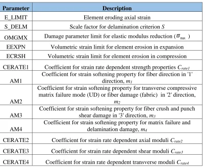
Table 3.2 Damage evolution, element deletion and strain rate parameters provided to MAT162 input deck
Parameter Description
E_LIMIT Element eroding axial strain
S_DELM Scale factor for delamination criterion S
OMGMX Damage parameter limit for elastic modulus reduction (
max )EEXPN Volumetric strain limit for element erosion in expansion ECRSH Volumetric strain limit for element erosion in compression
CERATE1 Coefficient for strain rate dependent strength properties Crate1
AM1
Coefficient for strain softening property for fiber direction in '1' direction, m1
AM2
Coefficient for strain softening property for transverse compressive matrix failure mode (UD) or fiber damage (fabric) in '2' direction,
m2
AM3
Coefficient for strain softening property for fiber crush and punch shear damage in '3' direction, m3
AM4
Coefficient for strain softening property for matrix failure and delamination damage, m4
CERATE2 Coefficient for strain rate dependent axial moduli Crate2
CERATE3 Coefficient for strain rate dependent shear moduli Crate3
CERATE4 Coefficient for strain rate dependent transverse moduli Crate4
Most of the parameters in Table 3.1 are self-explanatory. The AMODEL flag can be
set to 0 or 1 depending on the type of lamina being analyzed. If 0, then the unidirectional
is 1. The properties listed in Table 3.2 are utilized in the progressive damage evolution model.
The OMGMX (
max) parameter governs the extent of stiffness reduction in elastic and shear moduli. The damage evolution characteristic (Stress vs Strain) is exponential in nature and isgoverned by the parameters AM1 through 4. MAT162 allows for element erosion in the
composite panel governed by the axial and volumetric erosion strains. The final input deck
with values of moduli, strengths and damage evolution will look something like that shown in
Table 3.3 (S2/SC15 glass properties used in this study).
Table 3.3 MAT162 input properties for S2 glass/SC 15 composite panel [1]
MID RO EA EB EC PRBA PRCA PRCB
4 1850 kg/m3 27.5GPa 27.5GPa 11.8GPa 0.11 0.18 0.18
GAB GBC GCA AOPT
2.9GPa 2.14GPa 2.14GPa 2
XP YP ZP A1 A2 A3
0 0 0 1 0 0
V1 V2 V3 D1 D2 D3 BETA
0 0 0 0 1 0 0
SAT SAC SBT SBC SCT SFC SFS S_AB
604MPa 291MPa 604MPa 291MPa 58MPa 850MPa 300MPa 75MPa
S_BC S_CA SFFC AMODEL PHIC E_LIMIT S_DELM
58MPa 58MPa 0.3 2 10 0.2 1.2
OMGMX ECRSH EEXPN CERATE1 AM1
0.999 0.001 4.5 0 2
AM2 AM3 AM4 CERATE2 CERATE3 CERATE4
Material Coordinate System
AOPT flag seen in Table 3.3 allows for the definition of the material coordinate system
of the lamina with respect to a global coordinate system. The various options available for this
flag are specified in the user manual. The value chosen is 2.0 which implies global orthotropic
configuration. The flags A1, A2, A3 and D1, D2 and D3 are vector components used to specify
the material axes.
Figure 3.1 Definition of Material Coordinate system with AOPT=2.0 [43]
From Figure 3.1, vectors a and d are defined using A1, A2, A3 and D1, D2, D3
respectively. With A1=1 and D2=1, we get b along the global ‘y’ direction and c along global
‘z’ and a along global ‘x’ direction. a, b and c will be represented as A, B and C within the
MAT162 model respectively.
Strain Rate sensitivity
High strain rate loading during impact scenarios can cause considerable increase in
![Figure 2.1 Definition of Orthotropic directions in a lamina [28]](https://thumb-us.123doks.com/thumbv2/123dok_us/1634957.1203996/26.612.204.458.378.602/figure-definition-orthotropic-directions-lamina.webp)
![Figure 2.12 Solid elements with 8 nodes [43]](https://thumb-us.123doks.com/thumbv2/123dok_us/1634957.1203996/42.612.221.409.281.491/figure-solid-elements-nodes.webp)
![Table 3.3 MAT162 input properties for S2 glass/SC 15 composite panel [1]](https://thumb-us.123doks.com/thumbv2/123dok_us/1634957.1203996/49.612.98.534.327.582/table-mat-input-properties-for-glass-composite-panel.webp)
![Figure 3.1 Definition of Material Coordinate system with AOPT=2.0 [43]](https://thumb-us.123doks.com/thumbv2/123dok_us/1634957.1203996/50.612.274.382.255.390/figure-definition-material-coordinate-aopt.webp)
![Table 3.5 Damage History variables for UD and fabric lamina [46]](https://thumb-us.123doks.com/thumbv2/123dok_us/1634957.1203996/58.612.97.533.328.559/table-damage-history-variables-and-fabric-lamina.webp)