NUMERICAL SIMULATION ON COLLAPSE OF A SUPER-LARGE
COOLING TOWER CAUSED BY LOCAL FAILURE OF PILE
FOUNDATION
LI Yi 1, HUANG Shikui 2, HE Jiantao 2, GU Xianglin 3, SHI Famin 2, LIN Feng4
1Doctoral Candidate, Dept. of Building Engineering, Tongji University, Shanghai, CHINA
2Senior engineer, State Nuclear Electric Power Planning Design & Research Institute, Beijing, CHINA 3Professor, Dept. of Building Engineering, Tongji University, Shanghai, CHINA
4Associate Professor, Dept. of Building Engineering, Tongji University, Shanghai, CHINA
ABSTRACT
With the continued development of nuclear power plants, more and more super-large cooling towers are to be built in China and around the world. However, the collapse of super-large cooling towers may damage the nearby structures and nuclear facilities, and the ground vibration due to the collapse of the cooling towers may threaten the safe operation of the relevant nuclear facilities. Local failure of the pile foundation is one of the reasons which can cause the collapse of a cooling tower, but it has not come to people’s attention. The emphasis in present paper was given to the collapse behavior, the collapse modes and mechanism of super-large cooling towers due to local failure of pile foundations. Firstly, a 3D finite element model for a super-large cooling tower was developed and nonlinear material models were incorporated. Secondly, the simulation methods were verified by comparing the collapse mode of a cooling tower demolished by controlled explosion with the collapse mode of corresponding collapse process yielded from the numerical simulation. Finally, the different local failure regions of pile foundation were simulated and the collapse modes and mechanisms were discussed. It was found that the local failure which only covers one column can change the stress stage of the ring footing, but cannot induce the collapse of the cooling tower. Nevertheless, if the local failure covers more than 3 columns, it will lead to the collapse of the cooling tower. The collapse modes in different cases are almost the same, but the durations of collapse processes are different.
INTRODUCTION
As a part of nuclear power plants, cooling towers play a significant role for the availability of reliable energy supplies, in a manner compatible with environmental requirements. They definitely belong to the largest and thinnest concrete structures at present. Along with the increase in the height of cooling towers, the safety of the super-large cooling towers is more concerned. Pile foundation is commonly used for a super-large cooling tower. Its quality directly affects the safety of cooling tower structures. Local failure of the pile foundation can change the stress state of the tower body, even lead to collapse of the cooling tower. Once these super-large cooling towers collapse, the safety of buildings and structures, especially, the relevant nuclear facilities around the cooling towers will be threatened.
Studies on the collapse of the cooling towers can be traced to the research and investigation of the collapse of three natural draft cooling towers at the Ferry bridge power station in 1965. This accident spurred research into the wind dynamic responses and the theory of analysis about the cooling towers. Niemann (1979), Bender et al. (1996) and Zhao et al. (2010) analyzed static and dynamic effects of wind
on cooling towers by theoretical derivation and the wind tunnel experiments. The ultimate strength of cooling towers subjected to wind load was investigated by Hara et al. (1994) and Noh (2005). Krätzig and
towers were not be obtained because they used the yielding of reinforcement as the criterion to judge whether the ultimate load had been reached or not. On the other hand, it is vital to understand the responses of the cooling towers under earthquake excitations in the earthquake-prone areas. Wolf (1986) and Sabouri-Ghomi et al. (1996) analyzed the responses of a cooling tower under seismic forces by the
linear and nonlinear analysis respectively, the results showed that the columns supporting a cooling tower were profound because the columns were heavily loaded elements that do not possess high ductility. The cooling tower would be rendered unstable state and would collapse under the earthquake actions. Nevertheless, study on the other cases, such as the collapse of the cooling tower due to pile foundation failure, are few in the open literature.
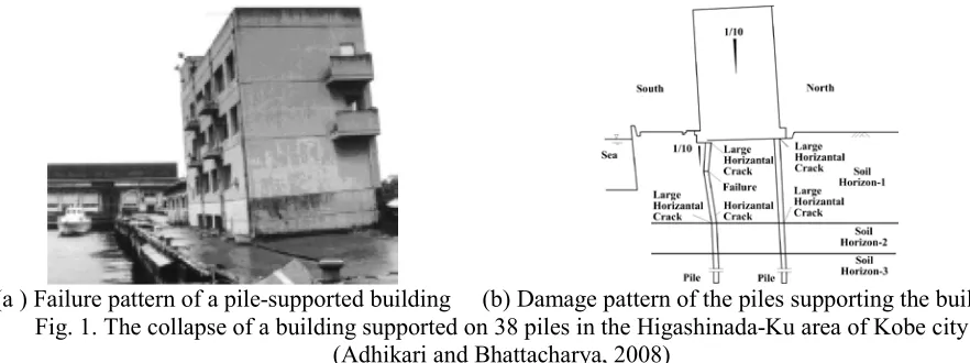
For some reasons, local failures of pile foundation may occur and this may induce the collapse and/or severe damage of pile-supported structures. The failures are often accompanied by settlement and tilting of the superstructure, rendering it either useless or very expensive to rehabilitate. As an example, Fig.1 shows the collapse of a building supported on 38 piles due to the local failure of pile foundation after earthquake and the damage pattern of the pile (Adhikari and Bhattacharya, 2008).
(a ) Failure pattern of a pile-supported building (b) Damage pattern of the piles supporting the building Fig. 1. The collapse of a building supported on 38 piles in the Higashinada-Ku area of Kobe city
(Adhikari and Bhattacharya, 2008)
The cooling tower consists of shell structure, ring beam, columns, ring footing and pile foundation, as shown in Fig.2. The pile foundation is routinely used to support the cooling tower. No matter what causes the local failure of the pile foundation, once the local failure beyond a certain range, it can change the stress state of the tower body, even lead to collapse of the cooling tower.
However, it is not exactly clear that how large the local failure region of the pile foundation for a cooling tower can lead to the collapse of the cooling tower. Meanwhile, the collapse modes and collapse mechanic behavior of the cooling towers caused by local failure of the pile foundation are not fully understood. So it is very significant to study the collapse modes and the collapse mechanisms of a super-large cooling tower caused by local failure of the pile foundation. The results can be used to accurately predict the ground vibration due to collapse of the cooling tower and to evaluate the safe operation of nuclear-related facilities adjacent to the cooling towers.
DESCRIPTION OF THE STUDIED CASES
The coordinate origin of the finite model was located at bottom plane. Z of the coordinate axis paralleled the central axis and its positive direction was upward. Fig. 3 shows the half model which used the X-Z plane as the symmetric plane and the location of key points for the structure. These key nodes can represent the movement behavior of the cooling tower in the process of collapse.
Inclined columns Shell structure
{
{ Throat
Ring-beam
HS
DH
DS Pile foundation{
Ring footing
Fig. 2. The structure of a cooling tower Fig. 3. Location of key nodes for structural modeling
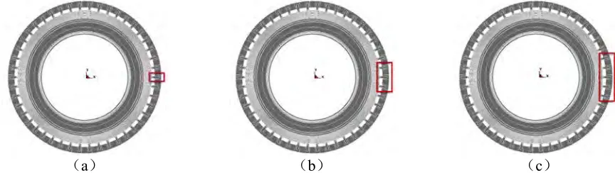
Three cases were investigated in this paper. Their differences were the local failure regions of pile foundation. The local failure regions of case 1, 2 and 3 were limited in the zone of pile foundation near the key point A where there were 1, 3and 5 columns respectively (Fig. 4).
(a) (b) (c)
Fig. 4. The local failure regions of pile foundation (Bird view)
FINITE ELEMENT MODEL
A three-dimensional finite element model was constructed using LS-DYNA software, as shown in in Fig. 5. In this model, the shell structure of the tower was modeled by 4-node shell element with both bending and membrane capabilities. By changing the values of the shell thickness at each of the 4 nodes, the continuously variable shell structure could be reasonably simulated. Since a large number of reinforcement bars were used in the shell structure, the concrete and reinforcement bars were modeled using an integral model. Every shell element was divided into 15 layers along the direction of thickness. Each layer could be assigned with certain materials separately (e.g., concrete, meridional reinforcement or circumferential reinforcement). The thickness and location of each layer were determined according to the design drawings of the cooling tower (Fig. 6). The concrete and reinforcement bars of columns and ring footing were modeled separately, as shown in Fig. 7 and Fig. 8. The concrete was modeled by hexahedral elements, and the reinforcement bars were modeled by beam elements. The elements of the concrete and reinforcement bars had common nodes at the interface between the concrete and the steel bars, and the slip between the two materials was ignored.
the effect of pile foundation in un-failed area of the ring footing was simulated. The local failure of the pile foundation was simulated by releasing the DOF of nodes which were located in corresponding failure area.
Fig. 5. The finite element model for the cooling
tower Fig. 6. Element of multilayer, multidirectional shell continuum in its actual state
Fig. 7. Hexahedral elements for concrete in the
columns and the ring plate foundation Fig. 8. Beam elements for reinforcement bars in the columns and the ring plate foundation
In the columns, the material model of the concrete was developed based on the Karagozian & Case (K&C) concrete model (Malvar, L. J., 1997), which could be used for the complex behavior of concrete subjected to large strains and high pressures.
The K&C concrete model decouples the volumetric and deviatoric responses. The model also uses an Equation of State (EOS). The Equation of State prescribes a user-defined set of pressures, unloading bulk moduli, and volumetric strains. Once the pressure has been determined from the EOS, a movable surface, or failure surface, will limit the second invariant of the deviatoric stress tensor (i.e.σ ). In addition, the model is strain rate dependent, which is extremely important for accurately simulating the case of the high strain rates.
The model uses a simple function to characterize three-invariant failure surfaces that define the yield, maximum, and residual strength of the material. Three parameters a0i, a1iand a2i (9 parameters total for the three surfaces) define each of the failure surface:
0
1 2
( )
i i
i i
p
F p a
a a p
= +
+ ⋅ (1)
Where, p is the pressure (i.e., mean normal stress) and Fi is the ith of three failure surfaces. For
performed between the maximum and residual surfaces. The damage parameter λ is defined using the following relationships: 1 0 f f t when 0 1 e e λ= ≥ +
∫
p p b d p p r r f (2) 2 0 f f t when 0 1 e eλ= <
+
∫
p p b d p p r r f (3)Where b1 and b2 are the user-defined parameters, which change the rate at which damage occurs, and the f
r value is a dynamic increase factor that accounts for strain rate effects. The effective plastic strain increment is given by:
2 3
p p p
ij ij
de = de ed
(4)
The material model of steel bars in the columns was the plastic kinematic model. It is suited to model kinematic hardening plasticity with rate effects.
In the shell elements, the aforementioned material models could not be used, due to the limitation of the LS-DYNA code. Another material model, named CONCRETE-EC2 (Hallquist, 2012), was selected. This model is a multipurpose model, it can represent plain concrete only, reinforcing steel only, or a smeared combination of concrete and reinforcement. The model includes concrete cracking in tension, crushing in compression, and reinforcement yielding, hardening and failure, which are widely used in shell elements. In the model, the parameters and equations of the concrete and reinforcement bars in the shell structure of the tower that govern the behavior of materials were determined according to Euro-code 2.
To simulate the contact and collision action during the collapse process of the tower, a contact model, CONTACT_AUTOMATIC_SINGLE_SURFACE, was incorporated into the calculation. The interface could be searched, and the contact could be judged automatically with this model, which was very important in addressing the complex situation.
Since LS-DYNA is a dynamic finite element analysis software, the modeled structure could continuously vibrate for a long time when the gravity load was directly applied in the calculation. To solve this problem, the simulation process was divided into two stages. First, the gravity load and a larger damping were imposed on the cooling tower, and the calculation was terminated after the cooling tower reached equilibrium. In the second stage, the large damping was removed, and full restart analysis technology was used. The stress state of the cooling tower under the gravity load at the end of the first stage was utilized, and the DOFs of nodes which were in the local failure area of the pile foundation were released, then the rest of the calculation was continued.
VERIFICATION OF NUMERICAL MODEL
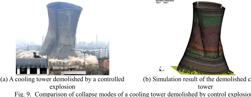
In order to validate the numerical methods, the collapse modes were compared between a cooling tower demolished through a controlled explosion and the simulation results of corresponding collapse process.
one in present paper. It was found that, in the process of falling, the shell structure buckled and some cracks appeared in the mid-lower part of the shell structure along the hoop. Due to the tension, the top part of the cooling tower deformed into an oval. There were three main cracks along the direction of the meridian. The simulated collapse mode of the tower was very similar to that of the actual tower demolished by a controlled explosion, both of which are showed in Fig. 9. The results of verification also indicated that this numerical modeling method could be used to realistically simulate the collapse modes and the collapse process of the cooling tower.
(a) A cooling tower demolished by a controlled
explosion (b) Simulation result of the demolished cooling tower
Fig. 9. Comparison of collapse modes of a cooling tower demolished by control explosion
NUMERICAL RESULTS AND ANALYSIS
Case 1: The Local Failure Scenario of Pile Foundation below One Column
The length of the local failure region of pile foundation along the circumferential was 11.6 m. Although the ring footing lost the support by the pile foundation in this zone, the ring footing could still bear the loads from the upper columns. So, only the small deformation was found in the shell structure which above the local failure region. The displacement distributions of the cooling tower reached steady state are showed in Fig. 9 and Fig. 10. The maximum value of displacement in X, Y direction was about 5, 15 mm respectively. It was found that there was no failure of construction members of the cooling tower and the central axis of the cooling tower did not tilt by calculating the relative locations of the key points.
Fig. 10. The displacement distribution of the cooling tower in X-direction in case 1 (t = 4.7 s)
Fig. 11. The displacement distribution of the cooling tower in Z-direction in case 1 (t = 4.7 s)
Case 2: The Local Failure Scenario of Pile Foundation below Three Columns
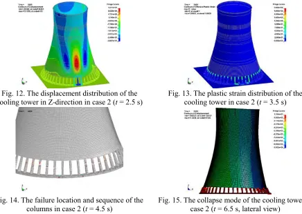
process is showed in Fig. 12. ~ Fig. 15.Because the ring footing of the failure zone lost support of the piles, the large vertical load from the upper columns led to the localized shear failure in the two sides of the ring footing of the failure zone. Meanwhile, the ring footing which located in this failure zone started to more downward obviously. The columns above this zone amounted to lose their load carrying capacity. This caused stress redistribution which significantly increased the load of adjacent columns. Under the action of gravity, the plastic strains mainly concentrated in the upper-middle parts of the columns. The progressive collapse of the cooling tower was triggered by the failure of the columns adjacent to this failure zone. The concrete of the columns crushed and the reinforcement could not bear the pressure accordingly, the columns failed successively along the circular direction and the collapse occurred like a row of dominoes falling down. The tilt angle of the shell structure gradually increased and the angel was about 3.0°when the edge of the structure slammed into the ground.
Fig. 12. The displacement distribution of the cooling tower in Z-direction in case 2 (t = 2.5 s)
Fig. 13. The plastic strain distribution of the cooling tower in case 2 (t = 3.5 s)
Fig. 14. The failure location and sequence of the columns in case 2 (t = 4.5 s)
Fig. 15. The collapse mode of the cooling tower in case 2 (t = 6.5 s, lateral view)
Case 3: The Local Failure Scenario of Pile Foundation below Five Columns
In case 3, the length of the local failure region of pile foundation along the circular direction was 58.4 m. This local failure region could cause severe damage in the ring footing. The collapse process, mode and mechanism were as the same as that in case 2. However, due to the larger length of local failure region, the collapse duration in this case was shorter than that in case 2 (Fig. 16~Fig. 22).
Summary and Analysis
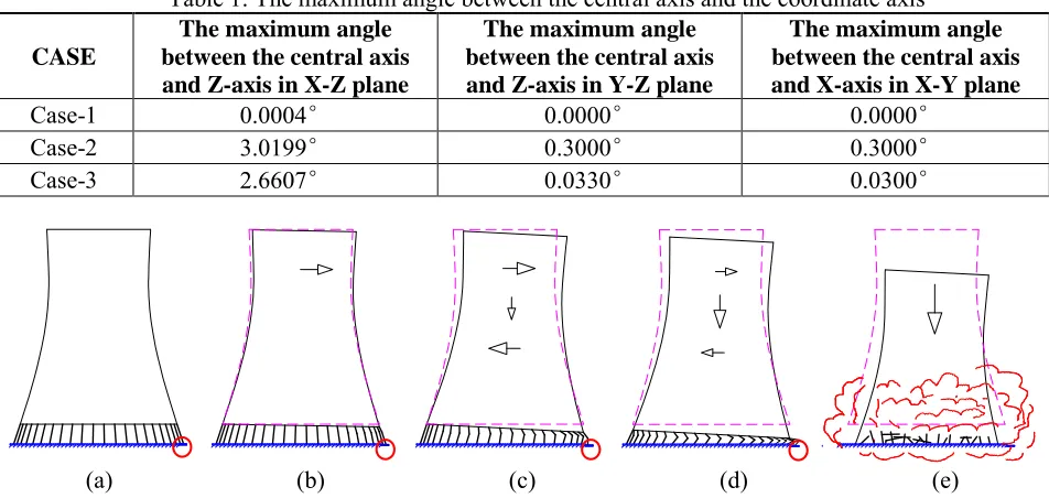
the spatial locations of key nodes (in Fig.3) in the process of collapse. It is believed that the dynamic collapse behavior was symmetrized to X-Z plane according to the maximum angle in Tab. 1. So the whole collapse process can be simplified into a two-dimensional problem for analysis. The sketches of collapse process were displayed in Fig. 20. This collapse mode was a typical progressive collapse mode. That was the initial failure of pile foundation caused local shear failure of the ring footing, consequently, the adjacent columns lost their load carrying capacity in turn, it led to the development of a chain reaction mechanism and progressive and catastrophic failure, eventually, the shell structure collapsed with a small angle of inclination (about 3°).
Fig. 16. The displacement distribution of the
cooling tower in Z-direction in case 3 (t = 2.5 s) Fig. 17. The plastic strain distribution of the cooling tower in case 3 (t = 2.5 s)
Fig. 18. The failure location and sequence of the
columns in case 3 (t = 3.0 s) Fig. 19. The collapse mode of the cooling tower in case 3 (t = 5.5 s)
The destruction of the columns were the combined results of the following two kinds of actions. On the one hand, the stress redistribution induced overstress inside the adjacent columns, once the loads beyond the capacity of the adjacent columns, the columns would be destructed. On the other hand, to balance the distributed inertia forces of the shell structure, a horizontal reaction force F at the base of
tower body needed, as shown in Fig. 21(b). In fact, this horizontal reaction force F was beared by the
columns. However, even though the tilt angel of shell structure was very small, the horizontal reaction force F would exceed the shear resistance of the columns. Bažant and Zhou (2002) analyzed the collapse
progress of the South Tower of the World Trade Center, they concluded that the reaction at the base of the upper part must have begun shearing the columns with titling angle about 2.8°. Even worse, the shear force would further reduce the vertical bearing capacity of the columns. So the combination of two actions would lead to the rapid failure of the columns in a short time. As shown in Fig. 22, the whole columns were destructed while the inclination of the shell structure was not exceeding 1° and the collapse durations were about 2 seconds in case 2 and case 3.
shell structure became predominantly vertical. Secondly, Because of the great size of the cooling tower, the center of gravity was not easily shifted out of the tower body. As a result, the angular velocity of the shell structure was very small.Thirdly, when the edge of shell slammed into the ground, the shell would stop tilt because the ground provided the support. So the cooling tower did not overturn in the whole collapse process. Since the shell structure would have large deformation after the edge of shell slammed into the ground, the angel of calculated value would no longer be accurate after this moment. So the curves in Fig. 22 were cut off in this time. But the graphical output of the collapse progress after this moment showed that the tilting angle was nearly unchanged for the three cases.
Table 1: The maximum angle between the central axis and the coordinate axis
CASE
The maximum angle between the central axis and Z-axis in X-Z plane
The maximum angle between the central axis and Z-axis in Y-Z plane
The maximum angle between the central axis and X-axis in X-Y plane
Case-1 0.0004° 0.0000° 0.0000°
Case-2 3.0199° 0.3000° 0.3000°
Case-3 2.6607° 0.0330° 0.0300°
(a) (b) (c) (d) (e)
Fig. 20. Scenario of tilting of shell structure of the cooling tower (columns deformation exaggerated, the circle denote the local failure region of pile foundation, the arrows denote the direction of motion)
H1
θ
x
(a)
mg F
N
1
mx H
θ
(b) Time (s)
Angle (
0)
The stage of
applying gravity The progress of collapse
The moment of the local failure of pile foundation
The start of the column failured The moment of half of the column failured The moment of all columns failured
The moment of the edge of shell slam into the ground
Fig. 21. Pivoting of the shell structure of tower about its base, (a) Model for simplified
analysis; (b) Free-body diagram with inertia forces
Fig. 22. The angle between the central axis and the Z-axis (in X-Z plane) vs. time
CONCLUSIONS
(1) The numerical modeling method in this paper could be used to realistically simulate the collapse modes and the collapse process of the cooling tower.
(2) Whether the cooling tower collapses depends on the length of the local failure region of pile foundation. If the local failure region covers more than 3 columns, it can lead to the collapse of the cooling tower.
(3) The collapse modes in these cases are the same, which unrelated to the local failure region of pile foundation. But the larger the local failure zone is. the shorter the collapse duration will be.
(4) The collapse mechanisms are identical. The local failure of pile foundation led to the shear failure of the ring footing, the support columns were gradually crushed due to the action of gravity and horizontal shear force, and finally the shell body moved downward with small tilting angle.
ACKNOWLEDGEMENTS
This research was supported by the National High-tech Research and Development Program of China (863 program) (Grand No.2012AA050903) and State Nuclear Electric Power Planning Design ﹠ Research Institute (SNPTC). The authors would like to extend their sincere gratitude to the Ministry of Science and Technology of the People's Republic of China and SNPTC for the financial supports.
REFERENCES
Adhikari, S. and Bhattacharya, S. (2008). “Dynamic instability of pile-supported structures in liquefiable soils during earthquakes”, Shock and Vibration, Vol. 15, No. 6, pp. 665–685.
Bažant, Z. P., and Zhou, Y. (2002). “Why did the World Trade Center collapse?—Simple analysis.”
Journal of Engineering Mechanics-ASCE, Vol. 128, No. 1, pp. 2–6.
Bender, T. J., Bergstrom, D. J. and Rezkallah, K. S. (1996). “A study on the effects of wind on the air intake flow rate of a cooling tower: Part 3 Numerical study”, Journal of Wind Engineering and Industrial Aerodynamics, Vol. 64, No. 1, pp. 73–88.
Hara, T., Kato, S. and Nakamura H. (1994). “Ultimate strength of RC cooling tower shells subjected to wind load”, Engineering Structures, Vol. 16, No. 3, pp. 171–180.
Hallquist, J. O., (2012). LS-DYNA Keyword User's Manual. Livermore Software Technology Corporation,USA.
Krätzig, W. B. and Zhuang, Y. (1992). “Collapse simulation of reinforced concrete natural draught cooling tower”, Engineering Structures, Vol. 14, No. 5, pp. 291–299.
LI Yi, LU Xiaoqin, LIN Feng, GU Xianglin. (2011). “Numerical simulation on damage or collapse of A super-large cooling tower subjected to accidental loads,” Transactions of the 21th International Conference on Structural Mechanics in Reactor Technology. New Delhi, India.
Malvar, L. J., Crawford, J. E., Wesevich, J. W., (1997) “a plasticity concrete material model for DYNA3D”, International Journal of Impact Engineering, Vol. 19, No. 9, pp. 847–873.
Niemann, H. J. (1979). “Static and dynamic effects of wind on cooling-tower shells”, Journal of Industrial Aerodynamic, Vol. 4, No. 3–4, pp. 243–246.
Noh, H.C. (2005). “Ultimate strength of large scale reinforced concrete thin shell structures”, Thin-Walled Structures, Vol. 64, No. 1, pp. 1418-1443.
Sabouri-Ghomi, S.,
Nik, FA,
Roufegarinejad, A. and Bradford, MA. (2006) “Numerical study of the nonlinear dynamic behaviour of reinforced concrete cooling towers under earthquake excitation”,Advances in structural engineering, Vol. 9, No. 3, pp. 433-442.
Wolf, J.P. (1986). “Seismic analysis of cooling towers”, Engineering Structures, Vol. 8, No. 3, pp. 191–
198.