293
Comparison study of CBF and EBF bracing operation in steel structures
Yasser khademi*1 Mehdi Rezaie2
1 B.Sc. Student, Department of Civil Engineering,University of maragheh, maragheh, Iran
Abstract
One of the most popular methods of lateral retrofit of braced steel frame is using diagonal steel bracing which is famous for concurrent bracing. Because of its easy operation and independence of any specific designing requirements, it happens to be the first choice of designers. Yet this bracing, in spite of having great and considerable difficulty, includes some weaknesses like low rate of deformation in comparison to divergence bracing. In this paper an eight floor steel frame structure in various bracing condition such as two kinds of concurrent bracing and three kinds of divergent bracing and one bending frame without bracing is being used and it is being analyzed by Static analysis method and then parameters such as lateral displacement , axial force , and an specified moment of a column is being compared and investigated.
Keywords:CBF Braced, EBF Braced, static analysis, Lateral displacement
1. Introduction
steel bracing frames are one of those types of structural systems which is being used in order to decrease lateral displacements in different structural floors. The bracing frames is often being used in order to stabilize the lateral loads but bracings could interfere in the architecture features. Bracings usually provide more feasible conditions for increasing rigidity and stability of structures under the lateral loads and it also decreases the lateral displacement by great consider.
the increasing of a frame hardness may cause the structure to absorb more inertia force from the happening earthquakes. In additional when the bracings decrease the bending moments and shear forces in columns in the other hand the axial force gets increased by bracings. The diverging bracings decreases the lateral hardness of structure systems and improves the energy wasting capacity. Because of the eccentric joining of the beams the lateral hardness of the structure system depends on the hardness curve of the beams. This paper represents an study about the treatment of steel structures with bracing and without bracing under the static condition and lateral loads applied to the steel structures. Gained Results of static analyses and the discussions about them is been represented in this paper. In conclusion the purpose of accomplished investigations is to determine the best performance by steel structures under the lateral loads.
2. Structural Modeling
294
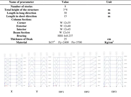
frame number 1 and 4 are including the bracing system resisting the lateral loads in X direction and the other frames have no bracing systems on them. Frame A and F have the same property in Y direction. The various quintet bracing systems being used in these frames are being represented in figure 2. It should be noted that all the beams, columns and bracings have the same size section in all used models. The properties of these sections are represented in table(1).This structure is been modeled by ETBS 9.6.0 application package and the linear static analyze is being done by with similar concurrent and diverging bracing systems. The project location is being located in Tabriz,Iran. The seismic specifications of following location are being extracted from Iran 2800 earthquake regulations.
Table (1): Structural properties
Unit Value
Name of prarameter
8
Number of stories
m
8 * 3
Total height of the structure
m
30
Length in long direction
m
15
Length in short direction
W 12x35 W 12x40 W 12x45
Column Section: Corner Exterior Interior
W 12x16
Beam Section
HSS 4x0.237
Bracing
cm
25
Thickness of Deak
Kg/cm2
St374 Fy=2400 Fu=3700
Material
Figure (3): Types of braces used
The loading is also being applied from both directions are absolutely symmetric. In loading calculations of this project 6th Iranian national regulation reference is being used.
3. Comparative studies
Various results have been gathered in short and long directions of earthquake loads and gravitational loads From eight modeled steel structure floors. The results from various kinds of bracing have been compared according to considered standards and criteria.
3.1. Lateral displacement story
The lateral displacements of different structural floors in long and short directions can be seen in figure (4) and figure (5) respectively. The analyze processing of this structure is being affected by huge dead and alive loading and special earthquake regulations. It can understood that the V type bracing includes the least lateral displacement and the EBF1 type of bracing includes the most amount of lateral displacement , also this amounts of displacement is comparable with the bending frame with no bracing system and 420 milimeters in long direction.
295
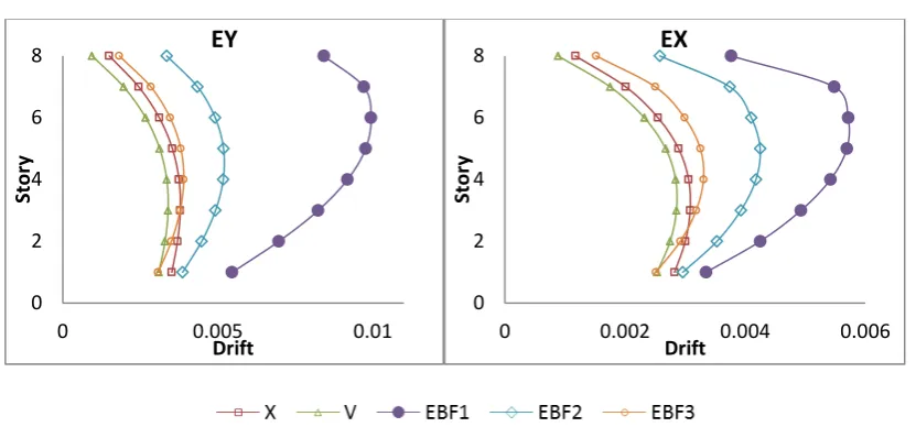
3.2. Relative lateral story
The difference in relative displacement of floor in different directions for floors with different sections for structures including and excluding bracing system is been shown in figure (6) and figure (7). It can understood that the V type bracing includes the least lateral displacement and the EBF1 type of bracing includes the most amount of lateral displacement , also this amounts of displacement is comparable with the bending frame with no bracing system with 0.026 long direction
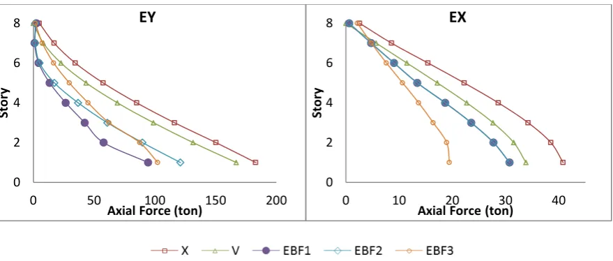
3.3. Column axial force
Because of the combinations of static effects and lateral loads, The change in axial loading for two corners and external surface of outer A frame in different structure floors is being shown in figure (8) and (9). It can be understood that the X type bracing includes the least amount of lateral displacement and the EBF1 type of bracing includes the most amount of lateral displacement , also these amounts of displacement are comparable with the bending frame with no bracing system with 31 tons in
Longitudinal
directionFigure (5): Lateral displacement story in direction long Figure (4): Lateral displacement story in direction short
Figure (7): Drift story in direction long Figure (6): Drift story in direction short 0
2 4 6 8
0 50 100 150 200
St
or
y
Displacement(mm)
EY
0 2 4 6 8
0 50 100
St
or
y
Displacement(mm)
EX
0 2 4 6 8
0 0.005 0.01
St
or
y
Drift
EY
0 2 4 6 8
0 0.002 0.004 0.006
St
or
y
Drift
296
Figure (9): Axial force side column in direction long Figure (8): Axial force side column in direction short
3.4. Column Bending Moments
Because of the combinations of static effects and lateral loads, The change in Bending moment for two corners and external surface of outer frame A in different structure is being shown in figure (10) and (11). It can understood that the X type bracing includes the least amount of lateral displacement and the EBF3 type of bracing includes the most amount of lateral displacement , also these amounts of displacement are comparable with the bending frame with no bracing system with 25 tons.m in
Longitudinal
direction.Figure (11): B.Moments side column in direction long Figure (10): B.Moments side column in direction short
3.5. The first period structures
The amount of first considered period for the matter of combined static affects and lateral loads has been shown in table (2). It is obvious that the X bracing system has the least amount in first period and the EBF1 bracing system has the most amount of first period. Also these two amounts can be compared to the non-braced bending frame system with 4.228 seconds.
Table (2): The first period structures
(sec) Period
Unbracing EBF3
EBF2 EBF1
V X
4.228 1.291
1.549 2.14
1.154 1.056
0 2 4 6 8
0 50 100 150 200
St
or
y
Axial Force (ton)
EY
0 2 4 6 8
0 10 20 30 40
St
or
y
Axial Force(ton)
EX
0 2 4 6 8
0 5 10 15
St
or
y
Moment(ton.m)
EY
0 2 4 6 8
0 5 10 15 20
St
or
y
Moment(ton.m)
297
3.6. Energy absorption
The energy absorbing amount for the matter of combined static affects and lateral loads has been shown in figure (12). It is obvious that the amount of energy absorbing in X bracing system has the most amount and the EFB1 bracing system has the least energy absorbing amount. Also these two amounts can be compared to the non-braced bending frame system with 23 Kg.cm.
Figure (12): The amount of energy absorbed against a variety of braces
4. Discussion on results
After the observation of the results in displacements of various structural floors represented in figure (4) and figure (5) , it is been stated that the lateral bracing system is decreasing the lateral displacements of structural floors widespread. Concurrent bracing , also, decreases the displacements of the structural floors considerably therefore it can be said that the concurrent bracings provides more lateral hardness for steel structures in comparison to the diverging bracings.
By referring to figure (5) , it can be stated that in structures by bracing systems in lower structural floors, the displacement amounts among floors is less than structures without bracing systems. It can be stated from figure (8) and figure (9) that the maximum axial force in corner and external surface of external column frame of A , braced , has a high amount whenever it has been combined by bracing systems. It is also been observed that the corner column’s axial forces have noticeable increasing rate from top to bottom in bracing structure systems yet there were no special change in corner columns in systems without bracing is been found. It can be stated from figure (10) that the maximum corner column moment in bracing structures , in two bottom floors is extremely high yet by applying non-bracing systems to high structural floors the moment decreases. It can be stated from figure (11) that the maximum moment amount of external column , when not being combined by bracing system, is extremely high.
Choosing the best option among all other options is very complicated procedure and highly depends on the engineering science related with the treatments of structural system. One of best methods could be the tree method in which the effected items like bending moment , axial forces , displacements and structural drifts with different weight systems ( with the sum of 100) being calculated and by considering the engineering science the best system with them best results would be selected and it will have the best performance.
𝛾
i= 1
−
𝑝𝑎𝑟𝑎𝑚𝑒𝑡𝑒𝑟
𝑝𝑎𝑟𝑎𝑚𝑒𝑡𝑒𝑟
(
𝑠𝑦𝑠𝑡𝑒𝑚
(
𝑚𝑎𝑥
)
)
𝛾
=
� 𝜔
𝑖𝛾
𝑖it is also noted that we can have this checking by stating some thesis or by the combination of ÿ in all elements ( column , beam , brace ) . for example : w1= 0.1 , w2=0.2 , w3=0.4 , w4=0.3.
Parameters 1, 2, 3 and 4 show respectively: Lateral displacement, lateral relative lateral, axial force, bending moment
X
V
EBF1 EBF2
EBF3
Unbracing
0 10 20 30 40 50
En
er
gy
(K
gf
.c
m
298
Table (3): The
𝛾
of structuresEBF3
EBF2
EBF1
V
X
Frame
44.75
51.449
54.4175
46.8044
43.3549
𝛾
According to the considered assumptions in this paper , it can be stated that the EBF1 method of bracing has the best performance in comparison to the other bracing methods.
5. Conclusion
The following results is gained by the accomplished studies :
1 – The amount of axial force in columns in non-braced bending frames has the lowest amount between the other frames.
2 – The lateral displacements in structural floors of steel structures is being decreased by X and V shaped concurrent bracing systems than the diverging bracings.
3 – According to the performance of diverging bracing system of EBF1 method , under the accomplished studies, these kinds of bracings are more suitable for steel structures.
4 – movements between structure floors is being decreased by applying the bracing system. As a conclusion it can be said that the bracing systems effects the lateral displacement of bottom the most.
5 – The amount of axial force in non-braced bending frame columns has the least amount between other kinds of frames.
6 – the amount of bending moments in non-braced bending frames has the highest amount between other kinds of frames.
7 – New criterion has been developed for comparing the various kinds of bracing systems based on the tree method and their weight.
9. References
1. BNBC(2006), Bangladesh National Building code, Housing and Building Research Institute, Dhaka, Bangladesh.
2. Etabs nonlinear Version 9.6.0 (1996), Extended 3D analysis of the building systems, computer and structures Inc., Berkeley, California, USA.
3. Earthquake Resistant Design of Buildings code, 2800, 4 th Edition, Edition 1393
4. AISC-ASD Steel Design Manual, 13th edition, American Institue of Steel Construction.