Volume 2008, Article ID 439203,7pages doi:10.1155/2008/439203
Research Article
Adaptive Delta-Sigma Modulation for Enhanced Input
Dynamic Range
Clemens M. Zierhofer
C. Doppler Laboratory for Active Implantable Systems, Institute of Ion Physics and Applied Physics, University of Innsbruck, Technikerstr. 25/3, 6020 Innsbruck, Austria
Correspondence should be addressed to Clemens M. Zierhofer,[email protected]
Received 20 December 2007; Revised 6 May 2008; Accepted 1 June 2008
Recommended by George Tombras
An adaptive delta-sigma modulator of 1st order with one-bit quantization is presented. Adaptation is instantaneous and based on an exponential law. The feedback signal is a multibit discrete-level signal generated by a digital-to-analog converter (DAC). Compared to a nonadaptive delta-sigma modulator of 1st order, the input dynamic range is significantly enhanced. The gain in dynamic range is 6 dB per bit defining the feedback amplitude. The influence of nonideal DAC performance is discussed. It is demonstrated that an implementation of the system is realistic with standard CMOS technology. To relax the requirements to the one-bit quantizer, the quantizer input signal is amplified adaptively (Q-Switching).
Copyright © 2008 Clemens M. Zierhofer. This is an open access article distributed under the Creative Commons Attribution License, which permits unrestricted use, distribution, and reproduction in any medium, provided the original work is properly cited.
1. INTRODUCTION
Delta-sigma modulators (ΔΣMs) in general are used to con-vert analog waveforms to high-frequency, but low-resolution data sequences (sometimes designated “ΔΣ-sequences”) [1, 2]. ΔΣMs inherently perform so-called noise shaping, whereby most of the quantization noise is shifted out of the base band toward higher frequencies, and thus the base band of theΔΣ-spectrum contains the spectrum of the input signal plus some residual quantization noise. The quality of signal representation is characterized by the signal-to-noise ratio (SNR), which is the ratio of the signal power to the power of the residual base band noise. Assuming that the power of the residual noise in the base band is approximately constant and independent of the input amplitude, the SNR is directly proportional to the power of the input signal itself. Thus the SNR is decreasing for decreasing input amplitudes. The basic idea of adaptive ΔΣMs is to adapt the amplitude of theΔΣ-sequence to the amplitude of the input signal such that the SNR roughly remains constant— at least within a specified range of input amplitudes. Various different types of adaptiveΔΣMs can be found in literature, for example, [3–9]. Adaptation algorithms based on “syllabic adaptation” [3,4,6,7] are controlled by short time
proper-ties, for example, by the peak amplitude, within so-called “stationary periods” (typically between 10–30 milliseconds for speech, and about 5 milliseconds for music [4]) of the input. Adaptation algorithms based on the instantaneous signal amplitude (“instantaneous adaptation” [5]) have the advantages that they do not require a priori assumptions on the stochastic properties of the input, and that there is no delay in the adaptation response. Besides, less circuitry is necessary for implementation.
The input power in adaptive ΔΣM can be estimated directly from the input signal itself (“forward estimation” [6]), or from the modulator output (“backward estimation” [3–5,7]).
[−c < x(n)< c] y0(n)∈ ±1 DAC
y(n)∈ ±c
[±1] z−1
+ +
−
Figure1: First orderΔΣM.
the nonadaptive version of the system. This is due to the instantaneous adaptation algorithm as presented here. In systems with syllabic adaptation, this effect does not occur, that is, the same peak SNRs are obtained for adaptive and nonadaptive versions [6,7].
The system in [5] also describes an instantaneous adaptation algorithm and a DAC for feedback generation. However, this algorithm is based on a linear, instead of an exponential law, which limits the maximum adaptation speed. As compared to the proposed system, a clearly inferior performance is obtained in cases of “adaptation overload,” that is, when the slope of the input signal is steeper than the maximum adaptation speed. Adaptation overload occurs, for example, when the input signal shows a sudden increase of signal power.
The adaptiveΔΣM [8] describes a step size adaptation algorithm which uses both sign and magnitude of the signal at the quantizer input. The current step size is increased, if the magnitude of the current quantizer input signal is larger than the previous step size, and decreased otherwise. While this algorithm yields a slightly improved peak SNR as compared to the system presented here (typically, between 3-4 dB), two bits are necessary for digital signal representation instead of only one bit for the system as presented.
Another adaptive ΔΣM is presented in [9]. However, the adaptation algorithm described here is primarily used to suppress tones close to half the sampling frequency, and not to enhance the input dynamic range. The SNR curve increases with increasing input amplitude level. As compared to the nonadaptive version of theΔΣM, the dynamic range is extended by 2 dB toward higher input levels, and the peak SNR is improved by 5 dB.
2. ADAPTIVEΔΣMODULATION—ANALYSIS
2.1. Basic concept
The simplest ΔΣM, a nonadaptive modulator of 1st order, is depicted in Figure 1. An input signal x(n) within the range of [−c, +c] is converted to the binary output sequence
y0(n) ∈ ±1. Sequencey0(n) is converted to the “physical” feedback signal y(n) ∈ ±cby means of a 1-bit digital-to-analog converter (DAC). Here and in the following, physical and numeric representations of signals are distinguished by labeling numeric one or multibit signals with the subscript “0.”
AΔΣM of 1st order can generally be regarded as a linear (nonadaptive) delta-modulator, whose input isnx(n), that
is, the accumulated input x(n). If the input is within the range of [−c < x(n)<+c], the magnitude of the maximum slope of the accumulated sequencex(n) is smaller thanc/T
(with T as sampling period). Thus, the delta modulator can theoretically always track its input, and the so-called “slope-overload conditions” cannot occur. In this model, parameter “c” represents the step size of the prediction signal
ny(n) = c
ny0(n), which tracks the accumulated input
nx(n). Condition|x(n)|< cis necessary and sufficient for
the elimination of slope-overload situations.
In an adaptiveΔΣM with instantaneous adaptation, step sizecis not fixed, but adapted to the localmagnitudeof the input,c→c(n). To avoid slope-overload, condition
x(n)< c(n) (1)
has to be fulfilled at any time.
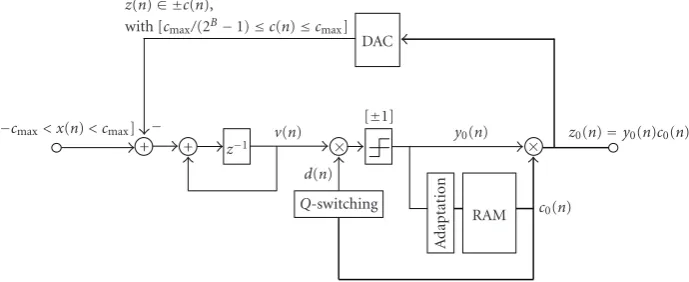
A block diagram of the adaptiveΔΣM as proposed here is shown inFigure 2. It contains the subtract-and-accumulate stage typical for 1st order ΔΣ modulation, and a 1-bit quantizer. In the adaptation stage, the quantizer outputy0(n) is used to generate a multibit step size amplitude c0(n). The numeric output of the system is the signal z0(n) = y0(n)c0(n). The physical signalz(n)= ±c(n), which is used as feedback signal, is generated by a DAC. If cmax is the maximum (physical) step size, the range of the input signal is given by [−cmax< x(n)< cmax].
The output v(n) of the accumulator is multiplied by a factor d(n), which is derived from c0(n) in a stage “Q -Switching.” However, since the quantizer detects only the sign of v(n), this multiplication plays a role only if the practical implementation of the system is regarded (cf. section“Q-Switching”).
Step sizec0(n) at a particular time instant is controlled by a set of code words [y0(n),y0(n −1),y0(n− 2),. . .], which are the instantaneous and a particular number of previous code words. The way the adaptation stage works is intuitively clear. Amplitudec(n) needs to be increased, if the set [y0(n),y0(n−1),y0(n−2),. . .] is composed of equal code words. In this case,|x(n)|tends to exceedc(n), which would violate condition (1). On the other hand,c(n) should be decreased, if the set [y0(n),y0(n−1),y0(n−2),. . .] shows an alternating pattern of code words.
The step size adaptation algorithm presented here is based on an exponential law. If the input signal shows an abrupt transition from high to low amplitudes, then step size sequencec0(n) is decaying roughly exponentially, where neighboring step sizes differ by about a factorα <1, that is,
c(n)≈αc(n−1). (2)
The decay is not perfectly exponential, since step sizes
[−cmax< x(n)< cmax]
×
× y0(n)
c0(n) RAM
z0(n)=y0(n)c0(n) DAC
v(n) d(n) Q-switching
Ad
ap
ta
ti
o
n
[±1] z−1
+ +
− z(n)∈ ±c(n),
with [cmax/(2B−1)≤c(n)≤cmax]
Figure2: AdaptiveΔΣM of first order.
oversampling ratio OSR=1/(2WT) (withΔΣclock period
T)
α=exp
− π
OSR
. (3)
The step sizes are generated by a DAC comprising B
magnitude bits and one sign bit, and thus the numeric step sizesc0(k) have to be represented by a finite set of integer numbers within the range [2B−1 ≥c
0(k)≥1]. Assuming index kwithin the range [0 ≤ k ≤ kmax], step sizesc0(k) are obtained by rounding the continuous-valued numbers of function (2B−1)αkto the next integers, that is,
c0(k)=round
2B−1αk. (4)
The maximum step size atk=0 isc0(0)=2B−1. Since the minimum step size is 1, sequencec0(k) is truncated at index kmax. The condition for truncation is
2B−1αkmax>1
2, (5)
resulting in
kmax=floor
−ln
22B−1
ln(α)
. (6)
Indicesk > kmaxwould yield step sizes equal to zero, which does not make sense in the present application. The set of step sizesc0(k) comprises an overall number ofkmax + 1 numbers which approximate an exponentially decaying function if k is increased from k = 0 to k = kmax. In the present system, all step sizes are stored in a look-up-table RAM at addresses from k = 0 to k = kmax. In a running modulator, changing of step sizes is achieved by simply shifting the instantaneous RAM-address to higher addresses for step size decrease, and to lower addresses for step size increase.
An example of an adaptation algorithm has been deter-mined empirically for best SNR performance, assuming a 9-bit DAC (B = 8) and an oversampling ratio of OSR =50. The numeric signalsz0(n) andc0(n) are composed of 9 bits and 8 bits, respectively. With (3), the exponential base is
α =0.9391, and with (6),kmax = 99, that is, 100 step sizes are stored in the RAM. The exact integer values of c0(n) are defined by (4). As shown in Table 1, the step size is decreased by about a factorα1(i.e., RAM address increased by 1 position) if four consecutive code words have alternating signs, and increased by approximately a factorα−3(i.e., RAM address decreased by 3 positions) if five consecutive code words are equal. The increase of c(n) occurs considerably faster than the decrease, since violation of condition (1) has to be avoided by all means. Empirically, a factor α−3 has proven to be sufficient.
Sample waveforms for an adaptiveΔΣM implementing the adaptation algorithm described in Table 1 are shown in Figures 3 and 4. The first trace in Figure 3 depicts an example of an input signal x(n). The second trace shows the full wave rectified version |x(n)| together with the magnitude c(n) = |z(n)| of the DAC-output signal. The third trace illustrates the full DAC-output signal z(n). In
Figure 4, signalx(n) is attenuated by 40 dB as compared to
Figure 3. As expected, the quantization of signalsc(n) and
z(n) appears more pronounced. The examples in Figures3
and4 demonstrate that the step size adaptation algorithm works instantaneously, that is, the feedback amplitudec(n) tracks the individual maxima and minima of|x(n)|.
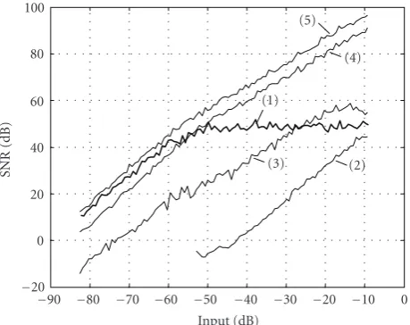
Figure 5depicts the SNRs of various types of analog-to-digital converters as a function of the input signal power. The input x(n) within the range of [−1, +1] is a periodic, zero-mean noise sequence composed ofN =4000 samples. Within a bandwidth W = 10 kHz, amplitudes and phases of the spectral lines are randomized. Different signal power levels are obtained by scaling this signal. The input power is referred to the power level of a dc-signal with amplitude +1. The sampling rate for all simulations is 1/T = 1 MHz (OSR =50), and the SNRs are computed within base band
W.
Table1: Adaptation algorithm.
Code Step size multiplier (α <1) [0≤k(n)≤kmax]
y0(n)=y0(n−1)=y0(n−2)=y0(n−3)=y0(n−4) c0(n)=round((2B−1)αk(n−1)−3)
y0(n)= −y0(n−1)=y0(n−2)= −y0(n−3) c0(n)=round((2B−1)αk(n−1)+1)
Other combinations c0(n)=c0(n−1)=round((2B−1)αk(n−1))
0 200 400 600 800 1000 1200 1400 1600 1800 2000 Timen
−1
−0.5
0 0.5 1
A
m
plitude
(a)
0 200 400 600 800 1000 1200 1400 1600 1800 2000 Timen
−1
−0.5
0 0.5 1
A
m
plitude
(b)
0 200 400 600 800 1000 1200 1400 1600 1800 2000 Timen
−1
−0.5
0 0.5 1
A
m
plitude
(c)
Figure 3: Example waveforms derived from an adaptive ΔΣM modulator of first order. First trace: input signalx(n). Second trace: rectified input signal |x(n)|and feedback amplitude c(n) (note:
c(n)>|x(n)|). Third trace: output signalz(n).
c(n) = cmax = 1. Obviously, the segment of curve (2) at low input levels is very similar to curve (1), shifted to the left by 48 dB. In this region, the adaptive ΔΣM operates equal to a nonadaptive ΔΣM with the minimum step size
c(n)=cmin=1/255. Note that compared to the nonadaptive ΔΣM, the input dynamic range of the adaptive ΔΣM is expanded by approximately 48 dB, corresponding to 6 dB per magnitude bit in the feedback DAC signal. In addition, the peak SNR is improved by about 6 dB. This improvement of peak SNR is due to the instantaneous adaptation algorithm, where the amount of quantization noise introduced into the system is adaptively controlled by the local magnitude of
|x(n)|. Hence, less noise power is introduced as compared to the cases with constant (i.e., no adaptation) or very slowly varying (i.e., syllabic adaptation) feedback amplitude. Curve (3) depicts the SNR of a 2nd orderΔΣM. While the SNR peak of curve (3) is better than the one of curve (1), for input levels below about−30 dB, the adaptiveΔΣM clearly outperforms the 2nd order system. Curves (4) and (5) depict the SNRs
0 200 400 600 800 1000 1200 1400 1600 1800 2000 Timen
−2
−1
0 1 2
×10−2
A
m
plitude
(a)
0 200 400 600 800 1000 1200 1400 1600 1800 2000 Timen
−2
−1
0 1 2
×10−2
A
m
plitude
(b)
0 200 400 600 800 1000 1200 1400 1600 1800 2000 Timen
−2
−1
0 1 2
×10−2
A
m
plitude
(c)
Figure4: Waveforms as shown inFigure 3, but input signalx(n) attenuated by 40 dB.
of pulse code modulation (PCM) systems with 13- and 14-bit resolution. Whereas the 14-14-bit PCM system is superior to the adaptiveΔΣM for all input levels, the 13-bit PCM system is inferior at least at low-level input signals.
Simulations have also been carried out with pure sinu-soidal input signals, and different frequencies have been examined. However, the results are not depicted, since they are qualitatively very similar to the results shown inFigure 5.
2.2. Influence of DAC imperfections
A nonideal DAC can be regarded as an ideal DAC plus a noise source. Unfortunately, the noise contributes directly to the noise energy in the base band of theΔΣM output, because no noise shaping effects take place. Thus, the properties of the DAC have critical influence on the performance of the adaptiveΔΣM.
−90 −80 −70 −60 −50 −40 −30 −20 −10 0 Input (dB)
−20
0 20 40 60 80 100
SNR
(dB)
(2) (3)
(1)
(4) (5)
Figure5: SNR for different ideal analog-to-digital converters. Input signals are band limited zero-mean noise signals withB=10 kHz (N = 4000). Curve (1): adaptive ΔΣM (9-bit DAC). Curve (2): nonadaptiveΔΣM of first order. Curve (3): nonadaptiveΔΣM of second order. Curve (4): 13-bit PCM. Curve (5): 14-bit PCM.
CMOS processes, capacitor matching is dominated by oxide variations resulting in
σ
ΔC C
=√AC
area, (7)
whereσis the standard deviation of the relative errorΔC/C, andAC is a process-dependent constant [10]. Simulations
have been carried out to estimate the influence of capacitor mismatch, taking the technology parameters of a typical 0.35μm CMOS process. A 9-bit DAC with 1 sign bit y0(n) and 8 magnitude bitsc0(n) is assumed, where the magnitude bits are represented by 8 binary weighted capacitors. The LSB capacitor with 25 fF requires an area of 29μm2. Taking a typical valueAC = 0.45%μm, (7) yieldsσLSB = 0.08%. The MSB capacitor which is 128 times larger requires an area of 3712μm2and yields a considerably smaller standard deviation σMSB = 0.007%. Note that the relative error is decreased, although the absolute error is increased. The simulations show that forσLSB<0.3% there is only negligible influence on the SNR performance as depicted in curve (1) in Figure 5. The performance starts to decrease for σLSB > 0.3%, and first signs of degradation appear in the region around the “SNR knee” for an input signal in the range of [−60 dB,−40 dB].
2.3. Q-switching
The adaptiveΔΣM concept described herein imposes addi-tional requirements on the specifications of the comparator, that is, the 1-bit quantizer. In practical implementations of comparators, the response time usually increases with decreasing input voltage difference. In ΔΣMs, too small comparator input differences might cause comparator fail-ures resulting in bit errors in the data stream. If those failures appear sporadically (single bit errors), they cause
Table2: Adaptation scheme forQ-switching.
Step sizec0(n) in binary representation
Overall capacitance
CACC,TOT(n)/CACC
Factord(n)
[1 x x x x x x x] 128 1/128
[0 1 x x x x x x] 64 1/64
[0 0 1 x x x x x] 32 1/32
[0 0 0 1 x x x x] 16 1/16
[0 0 0 0 1 x x x] 8 1/8
[0 0 0 0 0 1 x x] 4 1/4
[0 0 0 0 0 0 1 x] 2 1/2
[0 0 0 0 0 0 0 1] 1 1
“x” denotes “don’t care”
only negligible SNR degradation, and the ΔΣ concept in general is known to be robust against such errors. However, the density of failures must not exceed a particular limit.
In an adaptive ΔΣM, the probability for comparator failures is dramatically increased for low power input signals. Here, the feedback amplitudec(n) is small (cf.Figure 4), and thus the mean signal amplitude at the comparator input is also small. “Q-Switching” as described in the following is an approach to relax this problem.
The practical SC-realization of an adaptive ΔΣM as shown in Figure 2 usually involves a subtract-and-accumulate circuit consisting of an operational amplifier (opamp) with an integration capacitor, and capacitors for sampling the input signal (input capacitor) and the feedback signal (DAC-capacitors) (examples, e.g., in [1]). In the
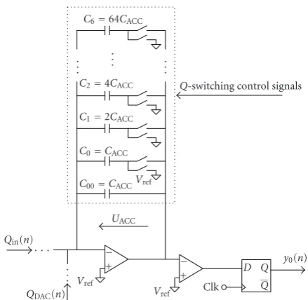
Q-Switching approach, the single integration capacitor is replaced by a variable capacitance. The basic idea is to adapt the integration capacitance to the instantaneous input signal power. For example, inFigure 6an overall integration capacitanceCACC,TOT(n) can be configured by means of an array of capacitors C00,C0,C1,. . .,C6. An example for an adaptation algorithm is summarized inTable 2.CACC,TOT(n) is derived from the position of the first logical “1” in the bit pattern of feedback magnitude c0(n), while bits at less significant positions (labeled “X”) are ignored. This method provides a rough estimate of the input signal amplitude and can easily be implemented. Capacitance CACC,TOT(n) decreases with decreasing input signal amplitude. Factor
d(n) is proportional to the inverse of CACC,TOT(n) (cf.
Figure 2).
sign detection have to be finished within the accumulation section, and therefore the response time of the comparator has to be shorter than 50% of oneΔΣclock period.
The integration capacitance is adapted during the sam-pling section of aΔΣclock period, that is, the preparation of charges Qin(n) in the input sampling capacitor, and QDAC(n) in the DAC are not affected. Two cases have to be distinguished, (i) an uncharged capacitor is added to, and (ii) a capacitor removed from the instantaneous configuration. One port of each capacitor of the array is permanently connected to the inverting input of the amplifier.
(i) An uncharged capacitor can simply be added to the array CACC,TOT by connecting its switched port to the amplifier output. This causes a redistribution of the charges and thus a change in the voltage
UACC. For example, if capacitor C1 = 2CACC is added to the active array, voltageUACCchanges from QACC/CACC,TOT to QACC/(CACC,TOT+ 2CACC), where QACCis the charge in the active array in the sampling section. The magnitude ofUACCis decreased in this case, since the overall capacitance has been increased at a constant charge.
(ii) Removing a capacitor from the active array is achieved by connecting its switched port to the reference voltage Vref. Since this potential is equal to the virtual potential of the inverting input of the amplifier, the amplifier forces the output to change its potential. For example, if capacitorC2=4CACCis removed, voltageUACCchanges fromQACC/CACC,TOT toQACC/(CACC,TOT−4CACC). As above,QACC is the charge in the active array in the sampling section. The magnitude ofUACCis increased in this case, since the overall capacitance has been decreased at a constant charge.
Note that for system performance, the exact value of
CACC,TOT is not critically important. The two essential requirements for the adaptation algorithm are that first, on average, the magnitude of voltage UACC is maximized without exceeding specified limits, and second, switching between different configurations of CACC,TOT has to be performed without any loss of charge (thus, the name Q -Switching). Any loss of charge in CACC,TOT would result in accumulation errors and thus degrade system performance.
3. SUMMARY
The essential properties of the proposed adaptive single-bit
ΔΣMs may be summarized as follows.
(1) The adaptation is “instantaneous” and controlled by a very small number of single bit code words (five for increase, and four for decrease of step sizes, cf.
Table 1). There is no need for computing short time power estimates or envelopes of the input as typically required in “syllabic” adaptation algorithms. (2) The adaptation scheme is based on an exponential
law, and for implementation, a DAC comprisingB
C6=64CACC . .
. ... .
. .
C2=4CACC C1=2CACC C0=CACC
C00=CACC
UACC Vref
Q-switching control signals
Qin(n)
· · ·
. . . QDAC(n)
Vref +
−
Vref +
−
Clk D
Q Q y0(n)
Figure6: Charge accumulation with variable integration capaci-tance (“Q-Switching”).
magnitude bits and one sign bit is used. Compared to a nonadaptiveΔΣM of 1st order, the overall gain in input dynamic range is about 6B dB.
(3) In addition to the enhanced input dynamic range, an improvement of the peak SNR of about 6 dB is obtained. This improvement is due to the instan-taneous adaptation. Since the feedback amplitude
c(n) tracks the individual maxima and minima of magnitude|x(n)|, on average less quantization noise is introduced as compared to systems based on syllabic adaptation.
(4) It is recognized that an increased input dynamic range imposes special requirements to the 1-bit quantizer. In SC-technology,Q-switching provides a means to relax this problem.
(5) The system can be implemented using standard SC-technology. Simulations show that state-of-the-art accuracy for the implementation of the DAC is sufficient to achieve the theoretically predicted SNR.
about 7500 speech processors utilizing the proposed adaptive
ΔΣM are in practical use.
REFERENCES
[1] J. C. Candy and G. C. Teme, Eds.,Oversampling Delta-Sigma Data Converters, IEEE Press, Piscataway, NJ, USA, 1992. [2] S. R. Northworthy, R. Schreier, and G. C. Temes,Delta-Sigma
Data Converters, IEEE Press, Piscataway, NJ, USA, 1997. [3] C. V. Chakravarthy, “An amplitude-controlled adaptive delta
sigma modulator,”The Radio and Electronic Engineer, vol. 49, no. 1, pp. 49–54, 1979.
[4] J. Yu, M. B. Sandler, and R. E. Hawken, “Adaptive quantisation for one-bit sigma-delta modulation,” IEE Proceedings G: Circuits, Devices and Systems, vol. 139, no. 1, pp. 39–44, 1992. [5] M. P. Jaggi and C. V. Chakravarthy, “Instantaneously adaptive
delta sigma modulator,”Canadian Electrical Engineering Jour-nal, vol. 11, no. 1, pp. 3–6, 1986.
[6] C. Dunn and M. Sandler, “Fixed and adaptive sigma-delta modulator with multibit quantizers,”Applied Signal Process-ing, vol. 3, no. 4, pp. 212–222, 1996.
[7] M. C. Ramesh and K. S. Chao, “Sigma delta analog to digital converters with adaptive quantization,” inProceedings of the 40th Midwest Symposium on Circuits and Systems, vol. 1, pp. 22–25, Sacramento, Calif, USA, August 1997.
[8] M. A. Aldajani and A. H. Sayed, “Stability and performance of an adaptive sigma-delta modulator,”IEEE Transactions on Circuits and Systems II, vol. 48, no. 3, pp. 233–244, 2001. [9] X. Sun and K. R. Laker, “Tonal behavior analysis of an
adaptive second-order sigma-delta modulator,” inProceedings of the IEEE International Symposium on Circuits and Systems (ISCAS ’02), vol. 4, pp. 277–280, Phoenix, Ariz, USA, May 2002.
[10] J.-B. Shyu, G. C. Temes, and K. Yao, “Random errors in MOS capacitors,”IEEE Journal of Solid-State Circuits, vol. 17, no. 6, pp. 1070–1076, 1982.