Image-Based 3D Face Modeling System
In Kyu Park
School of Information and Communication Engineering, Inha University, 253 Younghyun-dong, Nam-gu, Incheon 402-751, Korea
Email:[email protected] Hui Zhang
Computing Lab, Samsung Advanced Institute of Technology, San 14-1, Nongseo-ri, Giheung-eup, Yongin 449-712, Korea
Email:hui [email protected] Vladimir Vezhnevets
Graphics and Media Lab, Department of Computational Mathematics and Cybernetics, Moscow State University, Moscow 119899, Russia
Email:[email protected]
Received 31 December 2003; Revised 13 October 2004
This paper describes an automatic system for 3D face modeling using frontal and profile images taken by an ordinary digital camera. The system consists of four subsystems including frontal feature detection, profile feature detection, shape deformation, and texture generation modules. The frontal and profile feature detection modules automatically extract the facial parts such as the eye, nose, mouth, and ear. The shape deformation module utilizes the detected features to deform the generic head mesh model such that the deformed model coincides with the detected features. A texture is created by combining the facial textures augmented from the input images and the synthesized texture and mapped onto the deformed generic head model. This paper provides a practical system for 3D face modeling, which is highly automated by aggregating, customizing, and optimizing a bunch of individual computer vision algorithms. The experimental results show a highly automated process of modeling, which is suffi-ciently robust to various imaging conditions. The whole model creation including all the optional manual corrections takes only 2∼3 minutes.
Keywords and phrases:3D face modeling, image-based system, facial feature detection, generic head model, shape deformation, synthesized texture.
1. INTRODUCTION
The automatic generation of a realistic 3D human head model has been a challenging task in computer vision and computer graphics for many years. Various applications such as virtual reality, computer games, video conferencing, and 3D animation could benefit from convincing human face models. Although there are hardware devices such as laser range scanners and structured-light range finders that can capture accurate 3D shapes of complex objects, they are very expensive and difficult to use. The aim of this paper is to make a convincing human head modeling system that is easy to use by a common PC user. In order to achieve this, it is necessary to use affordable devices such as a digital camera for data acquisition to maximize the possible level of automa-tion along with the controls over the creaautoma-tion process and to develop robust algorithms that generates plausible results even in the case of imperfect input data.
In this paper, we develop a practical automatic system for generating a 3D convincing facial model from frontal and profile images, without imposing strict picture-taking con-ditions such as illumination, view angle, and camera calibra-tion. The proposed model deformation procedure works well even in the case of imperfect imaging, where the frontal and profile images are not strictly orthogonal. The novelty of the proposed system lies in the development of robust facial fea-ture detection algorithms, which are highly customized and optimized for face modeling purposes. In addition, the sys-tem achieves a visually accurate modeling of the ears, which affects the appearance dramatically but has not received a great deal of attention. The overall block diagram of the pro-posed system is shown inFigure 1.
1.1. Previous works
Input images Generic model Facial feature extraction Shape deformation Texture generation Resulting 3D model Synthetic texture
Figure1: Overview of the proposed system.
data they employ. A few researchers have developed tech-niques to acquire a 3D face directly from a laser scanner or a structured-light range finder [1,2]. However, it is very ex-pensive and difficult to operate to the extent that the com-mon end-users cannot use it. On the other hand, several studies have been devoted to the creation of face models from two or three views [3,4,5]. The views need to be strictly or-thogonal, which is difficult to achieve when using a common handheld camera without special mounter setup. A few sys-tems [6] rely on user-specified feature points in several im-ages, which is laborious. Among the other approaches, the methods that utilize optical flow and stereo methods appear to be the farthest step towards the full automatic reconstruc-tion process [7,8,9]. However, due to the inherent problems associated with stereo matching, the resulting models are of-ten quite noisy and exhibit unnatural deformations of the fa-cial surface. A few researchers attempted to build a model from just one frontal facial image by using depth estimation from 2D facial feature points [10]. However, the resulting model is yet far from convincing because it lacks both shape and texture information. The statistical model of the human head [11] has been used to introduce additional constraints for face modeling. However, the linear simplified represen-tation is doubtful, and the determination of the coefficients is very difficult to make efficient, robust, accurate, and auto-matic [12]. A system that makes it possible to combine sev-eral head shape data sources (stereo, 2D feature points, sil-houette edges) is described in [13]. However, the result was not a complete head and the algorithm is computationally complex.
1.2. Overview of the proposed system
The proposed system focuses on creating a highly automated procedure for a high-quality facial model generation from
the frontal and profile images without imposing strict con-ditions on the picture-taking concon-ditions. Special attention is paid to creating fast and robust facial feature extraction algo-rithms, which are customized and optimized to face mod-eling purposes. In addition, considering the limitations of computer vision techniques, this work allows optional user interaction for the manual corrections on top of the auto-matic reconstruction process. It should be noted that the proposed system does not require any camera calibration, which is in contrast to [13,14]. In addition, unlike [3,4,5], the frontal and profile views do not need to be strictly or-thogonal. Note that the input images for this system could be obtained using an ordinary digital camera, which makes the system easy to use and inexpensive.
As shown in Figure 1, the proposed system takes two (frontal and profile) photographs of a person and a generic head model as the inputs to produce a textured VRML model of the person’s head. Two types of data are carefully com-bined: the frontal and profile facial features. The recogni-tion part of the system extracts the facial features robustly. A few algorithms have been developed to detect the individ-ual facial parts including the eye, nose, mouth, ear, chin, and cheek. The generic head model is deformed to coincide with the detected facial features by employing radial-basis func-tions (RBF) interpolation. The model texture is created by blending the frontal and profile face photos after a color ad-justment to give the images a consistent color scale. In addi-tion, a synthetic skin texture is used to fill the model parts, where no texture information can be extracted from the pro-file and frontal images.
The proposed system is highly modular, allowing devel-opers to replace a particular subsystem with their own algo-rithm. Different generic head models can be used in the de-scribed system without difficulty. The user needs to create a semantics file only in which the correspondences between the facial feature curves and the model vertices are described. Note that it is possible to create a face model from a frontal image only.
1.3. Organization of the paper
The paper is organized as follows. In Sections 2 and 3, the algorithms for the frontal and profile feature detec-tion are described, respectively. Secdetec-tions 4 and 5 are de-voted to the shape deformation and texture generation algo-rithms, respectively. The experimental results are described in Section 6. Finally, Section 7 provides the conclusive re-marks.
2. FRONTAL FACIAL FEATURE EXTRACTION
(a) (b)
Figure2: Typical skin detection examples. (a) Input image. (b) Detected skin pixels marked in white.
2.1. Face region detection
Many face detection algorithms exploiting different heuristic and appearance-based strategies have been proposed (a com-prehensive review is presented in [15]). Among those, color-based face region detection has gained increasing popularity, because it enables the fast localization of potential facial re-gions and is highly robust to geometric variation of face pat-terns and illumination conditions (except colored lighting). The success of color-based face detection depends heavily on the accuracy of the skin-color model. In our approach, the Bayes skin probability map (SPM) [16] is employed in the normalized R/G chrominance color space, which has shown a good performance for skin-color modeling. Typical skin detection results are presented inFigure 2.
Skin color alone is usually not enough to detect the potential face regions reliably due to possible inaccuracies of camera color reproduction and the presence of nonface skin-colored objects in the background. Popular methods for skin-colored face region localization are based on connected components analysis [17] and integral projection [18]. Un-fortunately, these simple techniques fail to segment the fa-cial region reliably when the face is not well separated from what is mistakenly classified as “skin,” as shown inFigure 2b. In order to cope with these problems, a deformable elliptic model is developed, as shownFigure 3a. The model is initial-ized near the expected face position. For example, the mass center of the largest skin-colored connected region would be a good choice, as shown inFigure 3b. Subsequently, a num-ber (12 in the current implementation) of rectangular probes with an areaSprobe on the ellipse border deform the model to extract an elliptic region of skin-colored pixels, as shown in Figures 3c and3d. LetNin andNout be the numbers of skin-colored probe pixels inside and outside the face ellipse, respectively. The density of skin-colored probe pixels inside and outside the face ellipse then control the probe displace-ment vector−→vi:
− →v i=
l−kin· −→ni if SNin
probe < T 1,
kout· −→ni if SNout probe > T2
,
0 otherwise,
(1)
whereiis the probe index,−→niis the probe expansion direction (normal to the current ellipse border and pointing outside), andT1andT2are the threshold values. Nonnegative coeffi-cientkinandkoutcontrol the model deformation speed.
After the displacement vectors for all probes are calcu-lated, an ellipse is fitted to the centers of the repositioned probes. Taking advantage of the elliptical shape of the skin-colored region makes the method more robust, compared with the existing method for skin-pixel cluster detection as reported in [19].
2.2. Eye position detection
Accurate eye detection is quite important in the subsequent feature extraction, because the eyes provide the baseline in-formation about the expected location of the other facial features in the proposed system. Most eye detection meth-ods exploit the observation that the eye regions usually ex-hibit sharp changes in both the luminance and chrominance, which is in contrast to the surrounding skin. Researchers have used integral projection [20], morphological filters [18], edge-map analysis [21], and non-skin-color area detection [17, 22] to identify the potential eye locations in the fa-cial image. This leads to severe distortion errors when using a nonskin color and low pixel intensities as the eye region characteristics. Luminance edge analysis requires a good fa-cial edge map, which is difficult to obtain when the image is noisy or has a low contrast. However, the detection of sharp changes in the red channel image provides a more stable re-sult, because the iris usually exhibits low red channel values (for both dark and light eyes), compared with the surround-ing pixels in the eye white and skin. The proposed method effectively detects the eye-shaped variations of the red chan-nel, which is also easily implemented.
In order to more easily detect a change in intensity, the red channel image intensity is stretched to the maximum range and a variation image is then calculated. LetI be the original red channel image; the pixel value of the variation image at (x,y) can then be defined as
Vn,α(x,y)=Rα n,x,y
r∈Rn,x,y
I(r)−P1
n,r
p∈Pn,r I(p)
2 .
Ellipse
Probe
Exterior probe neighborhood
Interior probe neighborhood
(a)
(b) (c) (d)
Figure3: Face region detection with deformable model. (a) Deformable model. (b), (c), and (d) Convergence of the deformable model.
Here, Rn,x,y denotes an (n×7)-sized rectangle centered at (x,y), whilePn,r is an (n×n/3)-sized ellipse centered at r. The control parameters are the scaling coefficient,α, and the expected size of the eye features,n.
The meaning of the variation imageVn,α(x,y) can be
de-scribed as a dilatation of the high-frequency patterns in the red channel facial image. The variation image is calculated for several (n,α) pairs in order to cope with the high vari-ance of the eye appearvari-ance, as shown inFigure 4. This results in a stable and correct behavior for the images with diff er-ent lighting and quality. The connected componer-ents of the pixels with high variation values are then tested to satisfy the shape, size, and symmetry restriction in order to obtain the best-matching eye position for each variation image inde-pendently. Finally, different (n,α) configurations are sorted so that the later ones generate a stronger response. Their re-sults are combined in this order so that later rere-sults can either provide an output if no response is generated previously, or refine the previous results otherwise.
2.3. Eye contours detection
The eye contour model consists of an upper lid curve in a cu-bic polynomial, a lower lid curve in a quadratic polynomial, and an iris circle. The iris center and radius are estimated by the algorithm developed by Ahlberg [23]. This is based on the assumptions that the iris is approximately circular and dark against the background, that is, the eye white. Conven-tional approaches of eyelid contour detection use deformable contour models attracted as a result of the high values of the
luminance edge gradient [24]. Deformable models require the careful formulation of the energy term and good initial-ization, otherwise an unexpected contour extraction result may be acquired. Moreover, it is undesirable to use lumi-nance edges for contour detection, because eye area may have many outlier edges.
This paper proposes a novel technique that achieves both stability and accuracy. Taking the luminance values along a single horizontal row of an eye image as a scalar function Ly(x), it can be seen that the significant local minima
cor-respond to the eye boundary points, as shown inFigure 5. This observation is valid for many images taken under very different lighting conditions and qualities. The detected can-didate pixels of the eye boundary are filtered to remove the outliers before fitting a curve to the upper eyelid points. On the other hand, the lower lid is detected by fitting the eye corners and the lower point of the iris circle with a quadratic curve.
The eyebrows can be detected simply by fitting parabolas to the dark pixels after binarizing the luminance image in the areas above the eye bounding boxes.
2.4. Lip contour detection
(a) (b) (c) (d)
Figure4: Red channel variation images at different scales. (a) Input image with low quality and contrast. (b)n= FaceWidth/30,α=1.4. (c)n= FaceWidth/25,α=0.6. (d)n= FaceWidth/30,α=0.6.
(a) (b) (c)
Luminance
y
x
0
(d)
Figure5: Eye contour detection. (a) Source image. (b) Detected eyelid points and fitted curve. (c) Detected contour. (d) Pseudo 3D lumi-nance graph of the eye area. Candidate points for eye border are marked with dark circles.
person-specific skin-color histogram, located at the lower face part, are used to estimate the mouth rectangle. The skin and lip color classes are then modeled using 2D Gaussian probability density functions in (R/G, B/G) color space. It is observed empirically that this color space shows excellence in discriminating lip from skin. The difference between the lip and skin probability for each pixel is used to construct a so-called “lip function image,” which is shown in Figures6b and6c.
The initial mouth contour is approximated by an ellipse based on the pixel values of the lip function image. The con-tour points move radially outwards or inwards, depending on the lip function values of the pixels they encounter. Three forces control the displacement of theith contour point, as given by
Fi=Fidata+Fiform+Fism, (3)
where
Fdata
i =
−koutνc
, f pi≥T, kinνc, f pi
< T,
Fform
i =kform νp
+νn·νc
νp+νn νc,
Fsm
i =2ksm 1 +νp·νn
sgn pi+1−pi−1
· ν⊥ p
νc,
(4)
where kin,kout,kform, andksm are positive coefficients that control the contour deformation speed; f(pi) is the value of the lip function at pi on the lip contour; T is a threshold; νn,νp, andνcare the unit vectors pointing to the next
pi+1
pi νn
νc νp
pi−1
−ν⊥
p
(a) (b) (c)
Figure6: Lip contour detection. (a) Layout of control forces. (b) Contour after one iteration. (c) Contour after 12 iterations.
(a) (b) (c)
Figure7: Nose contour detection. (a) Luminance gradient vector field of the nose area with nose-side parts marked. (b) Nose-side candi-dates. (c) Detected nose curves.
In (3) and (4),Fiform is the data force that controls the growth and contraction of the contour.Fiformmaintains the contour shape to be close to an ellipse.νnandνpare taken as average of several neighbor points in order to make this force affect the global contour form.Fsm
i controls the smoothness
of the contour, whilst preventing each point from going out-side. The force direction is set to be parallel to the ellipse radii
−νc, which results in a more stable behavior during
conver-gence. The mouth contour points are moved until their dis-placements become less than a given threshold. Note that 30 iterations are sufficient in most cases.
In order to match the lip corners exactly, the smoothing forceFismis weakened for the points expected to become the lip corners by loweringksm for the corner neighbor points. The lower part of the mouth contour should be smoother than the upper part, which is also considered in assigning ksm. The intermediate process of contour fitting is illustrated in Figures6band6c.
2.5. Nose contour detection
The representative shape of the nose side has already been ex-ploited in order to increase the robustness, and its matching to the edge and dark pixels has been reported to be success-ful [24,25]. However, in cases of a blurry picture or ambient face illumination, it becomes increasingly difficult to utilize the weak edge and brightness information. In our approach, a step further from the naive template methods is made. The proposed approach utilizes the full information of the gra-dient vector from the edge detector. The nose-side template represents the typical nose-side shape in a fixed scale. In or-der to compensate for the fixed scale of the template, the nose image (face part between the eye-centers, vertically from the eye bottom to the top of mouth box) is cropped and scaled
to a fixed size. Median filtering is applied before template matching in order to alleviate the noise, whilst preserving the edge information. Luminance gradient vector field is cal-culated using Prewitt edge mask, which shows less blurring artifacts than Sobel mask when calculating the luminance derivatives. The result of the luminance gradient vector field is shown inFigure 7a. The figure of merit (FoM) at a pixel locationqis defined by the following formula:
FoM(q)=
p∈S(q)
Fit(p), (5)
where
Fit(p)=
1 if∃r∈Ω(p) s.t.∇−−→I(r)·−−→a(p)≥0.9 and∇−−→I(r)> T1,
0 otherwise.
(6)
In (6), p, q, and r denote pixel locations; S(q) is the set of template points;Ω(p) is a 5×5 neighborhood ofp;
Upper points with fixedY
4th-degree curve
Curve sections
Junction point
(a) (b) (c) (d)
Figure8: Chin and cheek contour detection. (a) Deformable contour model. (b), (c), and (d) The results of contour initialization and fitting.
As shown in Figure 7c, the final nose curves are estimated from the nose-side position and by considering a geomet-ric relation on the general human face structure between the eyes and nose.
2.6. Chin and cheek contour detection
Deformable models [26] have proven to be efficient tools for detecting the chin and cheek contour [27]. However, in several cases, the edge map, which is the main information source for a face boundary estimation, results in very noisy and incomplete face contour information. A subtle model deformation rule derived from the general knowledge on the human facial structure must be applied for accurate detec-tion [27]. This paper proposes a simpler but robust method that relies on a deformable model, which consists of two fourth-degree polynomial curves linked at the bottom point, as shown inFigure 8a. The model deformation process is de-signed in such a way that permits the detection of the precise facial boundary in the case of noisy or incomplete face con-tour. The gradient magnitude and the gradient direction are utilized simultaneously.
The model’s initial position is estimated from the al-ready detected facial features, as shown in Figure 8b. After the initialization, the model begins expanding towards the face boundaries, until it encounters strong luminance edges, which are collinear with the model curves. The model curves are divided into several sections. It expands until a sufficient number of pixels occupied by a curve section have an edge magnitude greater than a given threshold and an edge direc-tion collinear with a model curve. The model curves are fit-ted to the repositioned section points by least-square fitting after evaluating each section’s displacement. This is repeated until the model achieves a stable convergence. Figures8b,8c, and8dillustrate this process, showing the convergence to the actual chin and cheek boundary. The lower chin area may ex-hibit weak edges or no edges at all. In this case, the lower-part sections stop movement when they reach the significant lu-minance valleys. In order to prevent the excessive downward expansion, the model is not allowed to move lower than the horizontal line, which is derived from the human face pro-portions.
3. PROFILE FACIAL FEATURE EXTRACTION
The profile feature extraction consists of two steps: profile fiducial points detection and ear boundary detection.
3.1. Profile fiducial points detection
The algorithm can be roughly divided into two stages that include profile curve detection and fiducial points detection. The robustness is achieved by a feedback strategy: the later steps will examine the results from previous steps. When er-roneous intermediate results are detected, the algorithm will automatically go back to previous steps and fix the errors with additional information.
3.1.1. Profile curve detection
Profile facial curve is detected as the boundary of the face region, which is the largest skin-colored connected compo-nent, or another near the image center when the two largest components have a comparable size. Note that the same skin-color classification algorithm for the frontal image is em-ployed.
(a) (b) (c)
(d) (e) (f)
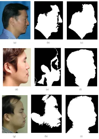
(g) (h) (i)
Figure9: Failure cases of color-based segmentation and the corrected results by area segmentation. (a), (b), and (c) The case of separate skin and nose. (d), (e), and (f) The case of incomplete nose area. (g), (h), and (i) The case of incomplete chin area. (a), (d), and (g) Input images. (b), (e), and (h) The results of color-based segmentation. (c), (f), and (i) The results of area segmentation.
is used to detect the profile curve, as shown in Figures 9c, 9f, and9i.
3.1.2. Fiducial points detection
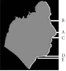
The profile fiducial points are detected after extracting the profile curve. They are defined as a few characteristic points positioned on the profile curve. First, a “profile function,” x = x(y) is constructed, where yvaries along the vertical direction, and x denotes the rightmost x coordinate. It is also smoothed with 1D Gaussian filter to eliminate noise. Figure 10shows a typical profile function, where a few fidu-cial points to be detected are also marked. The “nose tip” (A inFigure 10) is the global maximum position. The “nose
B A C
D E
Figure10: Typical profile function. Nose tip (A), nose bridge top (B), under-nose point (C), chin point (D), and neck top point (E) are marked.
lip points are positioned as the interpolation results of the under-nose point and the neck top point with predetermined coefficients. The distance from the nose tip to the chin point is then calculated. If it is too short, the third failure condi-tion of the skin-color segmentacondi-tion is recognized, as shown inFigure 9h. This is due to the insufficient illumination. For this case, the algorithm will return to the previous stage in or-der to redetect the profile curve with the area segmentation algorithm.
3.2. Ear boundary detection
Since the local low-level clues are usually weak and erroneous in the area around the ear, a curved template, which repre-sents the priori knowledge about the human ear, is utilized to detect the ear boundary. The complete ear detection consists of three steps: (1) profile image normalization to compensate for the different scale and orientation, (2) ear initialization to match the template with the image ear and to translate it to an initial position, and (3) ear refinement to deform the tem-plate in order to match the accurate ear boundary.
3.2.1. Profile image normalization
Two profile fiducial points, the nose bridge top and the chin point, are selected as the calibration points for normaliza-tion. The original image is rotated to make the segment con-necting them vertical, which is then scaled to make the dis-tance between them a predefined value. These two points are selected because they could be detected robustly, and they are distant enough so that the normalization is less sensitive to their detection errors. In this stage, a rectangle is also defined as the search area for the ear by statistical analysis on the rel-ative positions between the ears and the calibration points in our test images.
3.2.2. Ear initialization
As described previously, a curve template is utilized for the ear initialization and refinement. In this implementation, the template is a five-degree polynomial, as shown inFigure 11 (the thick white curve). The “skin-color boundary” (the boundary of the face region detected with the skin-color clas-sification) is used for ear initialization because it coincides
with the ear boundary at some partial segment in most cases, as shown in Figure 11. The problem is then to identify the corresponding partial segment between the template and the skin-color boundary inside the search area. After the scale and orientation normalization, it can be solved with a sim-ple curve-matching algorithm based on the similarity of the curve tangent.
In more detail, the two curves are preprocessed to be 4-connected, thereby avoiding local duplication. The resultant point sets are denoted as {qi ∈ R2} |
1≤i≤N for the
tem-plate, and {pj ∈ R2} |
1≤j≤M for the skin-color boundary,
respectively. Next, two displacement arrays are constructed as{VQs=qa(s+1)−qas}and{VPt =pa(t+1)−pat}, wherea is a coefficient for the sampling step.l(s,t) is evaluated as the maximum integerlthat satisfies
l
m=1
VQs+m−VPt+m≤δ, (7)
whereδis a threshold to measure the similarity in the tangen-tial direction atqasandpat. The position (sm,tm), wherel(s,t) is a maximum, gives a match result as {qi} |asm≤i≤a(sm+lm) and {pj} |atm≤j≤a(tm+lm). Finally, the template is translated based on the partial segment match. The proposed initial-ization method works very well in experiments, as shown in Figure 11.
However, the skin-color boundary has no coincidence with the ear boundary when hair is too short or the illumi-nation is too strong, as shown inFigure 12. Such cases can be automatically detected during the previous match process by selecting a threshold forl(sm,tm). In this case, an attempt is made to initialize the ear by employing edge information. A Nevatia-Babu edge detector [29] is selected in our im-plementation for its simplicity and good performance. The edges are thinned and linked together to generate long seg-ments. The previous curve-matching algorithm is then uti-lized again between the template and the edge segments in order to obtain the matched partial segments and a transla-tion vector for the template. In order to determine the “best” edge segment, the following factors are considered.
(i) The length of the matched partial segment for each edge segment: longer is better.
(ii) The translated template position: it should be inside the search area.
The result of ear initialization is shown inFigure 12.
3.2.3. Ear refinement
Based on the initialized ear template and the matched segment on the ear boundary image, a contour-following method is developed to deform the template to match with the whole ear boundary.
(a) (b) (c)
(d) (e) (f) (g)
Figure11: The results of ear initialization with skin-color boundary (thin grey curve), translated ear template (thick white curve), and the matched partial segments (thick black curve) on both skin-color boundary and the ear template.
(a) (b) (c) (d)
Figure12: The results of ear initialization using edge segments when skin-color boundary is incorrect.
is denoted as Contnext. The segment is rotated to a new po-sition that gives the best match evaluation, which will be de-fined in the next paragraph. All the connected segments after Contnare rotated together, as illustrated inFigure 13. Finally, lettingn=next, this operation is performed iteratively to de-form the whole template. This procedure is employed twice for both directions of the polyline.
Contn Contnext
New Contn
Figure 13: The template segments before (solid line) and after (dashed line) rotation, during ear contour following.
should not be too different from the value computed for its precedent. If any of these two requirements is not satisfied, the contour following terminates with a failure alarm. The initialized ear template is used for the failure cases. Note that this occurs mainly when the hair occludes ear.
For the ear bottom direction, the template length may be not adequate for matching with the ear boundary. Therefore, the “tail” of the template is replaced with a long line segment. The real bottom position of the ear is found by examining the edge strength along the deformed template.
4. SHAPE DEFORMATION
In the proposed system, new models are created by deform-ing the generic head model. The generic model is created by averaging a few laser-scanned faces and is simplified to ap-proximately 20 000 triangles. The generic model is deformed to fit the extracted facial features using the radial-basis func-tions (RBFs). Two algorithms are developed in order to cope with the conflicting facial features in the frontal and profile images. One is the preprocessing of the detected profile facial features; the other is the new deformation algorithm.
4.1. RBF interpolation
Suppose there are two corresponding data sets, {ui ⊂ R3} and{ui ⊂R3}, representingN pairs of vertices, that is, the key points, before and after the data interpolation. The fol-lowing f(p) can be determined as the deformation function of the whole 3D space [30]:
f(p)=c0+
c1c2c3
p+
N
i=1
Λiϕi p−ui, (8)
wherepis any 3D position andϕiis the RBF forui. In this implementation,ϕi(r)=e−r/Ki, whereKiis a predetermined coefficient that defines the influencing range ofui.c0,c1,c2, c3, andΛiare all vector coefficients, which are determined by solving the following constraints:
f ui=ui |Ni=1, (9)
N
i=1
Λi=0, (10)
N
i=1
ui,jΛi=0|j=x,y,z. (11)
Based on the RBF-based deformation framework and the 3D correspondences at the given key points between the fea-tures in the generic model and the input image, the generic model is deformed in order to generate a complete individ-ual model by feeding all the vertices in the generic model into (8). The key points are defined as the fiducial facial features, as shown inFigure 14.
4.2. 2D/3D key points generation
The key points represent perceptually important facial fea-ture points, by which most of the geometric characteristics of individual humans can be determined. In this approach, 160 fiducial points are sampled from the detected facial features. The key points are sampled along each contour such that it has the same sampling rate in the relative contour length as that of the key points on the corresponding contour of the 3D generic model. Note that the key points in the 3D generic model are predefined.
4.3. Preprocessing of the profile key points
Before performing the model deformation, the detected pro-file key points are preprocessed in order to cope with the incoherent frontal and profile facial features due to the nonorthogonal picture-taking condition. Two steps, a global transformation and a local one, are followed in order to com-plete this task.
During the global transformation, all the key profile points are scaled and rotated to match the frontal image. Scaling is necessary to compensate for the different focal length and viewing distance. The scale coefficient is deter-mined, based on the vertical distance of the two fiducial points, that is, the nose bridge top (NBT) and the chin point (CP). Rotation is also needed because the camera may be slightly rotated around the optical axis, or the pitch angle of the specific head is changed whilst taking the picture. How-ever, it is difficult to determine the rotation angle because of the lack of available information. In this system, the angle be-tween the vertical axis and the line connecting the NBT and the CP is assumed to be uniform for individuals and an at-tempt is made to rotate the profile key points such that the angle between the line and the vertical axis is equal to the angle observed in the 3D generic model.
During the local transformation, the profile line is par-titioned into different segments based on a few key points such as the nose, mouth, and chin points. Each segment is scaled separately in the vertical direction to coincide with the frontal features, as shown inFigure 15.
4.4. Model deformation
(a) (b)
Figure14: The key points marked in the generic model. (a) Frontal key points. (b) Profile key points.
Figure15: Local transformation on profile feature points.
image positions under the frontal view, and theZcoordinate remains the same as in the generic model. After RBF interpo-lation, the accurate match between the model and the frontal feature is achieved. The deformation result of this step is de-noted as M1.
Next, the profile key points are used to perform the RBF interpolation. TheYandZcoordinates of the displaced key points (uiin (9)) are set to their corresponding profile image positions, and theXcoordinates remain the same as in the generic model. During this step, theZvalues are determined for all model vertices. The deformation result of this step is denoted as M2.
Finally, all the key points are used to determine the re-sulting head shape. In this step, the profile key points retain their positions in M2. Regarding the frontal key points, their Zcoordinates are set according to M2, and theXandY co-ordinates are set according to M1. The final shape matches the detected 2D facial features in both view angles.Figure 16 shows a few created head shapes.
5. TEXTURE GENERATION
Being mapped onto the deformed 3D wireframe model, the texture provides the major contribution to the visual appear-ance and the perception of the model. This section describes
the texture generation method, including the frontal and profile facial color adjustment, texture mapping to a public plane, and blending the frontal and profile textures.
5.1. Color adjustment
The color scale of the skin pixels in the frontal and profile images may be different due to the difference in the lighting condition or the camera color balance. This produces un-desirable artifacts in the blended texture. In order to avoid this, color transfer between frontal and profile images is per-formed in the lαβcolor space [31]. Note that thelαβcolor space is known to have a low correlation between the color channels whilst having a closeness to the channel meanings in the human color perception. The results of the color ad-justment are shown inFigure 17, in which source image, tar-get image prior to adjustment, and the tartar-get image after ad-justment are shown in each row, respectively.
5.2. Texture mapping to a public plane
Figure16: Examples of the deformed head models.
(a) (b) (c)
(d) (e) (f)
Figure17: The results of color adjustment. (a) and (d) Reference image. (b) and (e) Input source image before adjustment. (c) and (f) Output image after adjustment.
also makes it easy to combine the texture from a real photo with a synthetic texture.
Because the human head is similar to a sphere-like shape, spherical texture mapping is used to ensure the even distri-bution of the model vertices across the texture coordinate space. The directly generated space is further repaired man-ually in order to solve the overlap problem, (i.e., in ear areas) on the UV plane. Note that this procedure requires no user interaction, because the UV plane is created with the generic model and remains constant when the individual models are created.
In order to create a textured model, the color-adjusted photos are mapped onto a UV plane. Since the model key points have been fitted to the image feature points, the cor-respondence between the model vertices and the image fea-ture positions are already known. The mapping is used twice for the frontal and profile photos, resulting in two individual texture images.
5.3. Texture blending
The frontal and profile textures should be blended together to generate a final texture on a UV plane, which is then mapped to the created 3D model during rendering. For each point p∈ {(x,y)|x,y∈[0, 1]}in the UV plane, the color of the blended texture is obtained by the interpolation as fol-lows:
C(p)=kf(p)Cf(p) +ks(p)Cs(p), (12)
where Cf,Cs are the colors at point p for the frontal and profile textures;kf,ksare the normalized weights for the dif-ferent textures, yieldingkf(p) +ks(p)=1 for everyp.
(a) (b)
Figure18: The effect of using synthetic texture. (a) Simple texture mapping. (b) Improved result by using the public UV plane and the synthetic texture mapping.
Figure19: Generated combined texture on the public UV plane.
(a) (b)
Figure20: Developed face modeling system. (a) Feature extraction module is working. (b) The generated 3D model is being rendered.
the utilization of the blending boundary with an arbitrary shape.
In this approach, a couple of additional techniques are used to improve the texture quality. One is the utilization of the synthetic texture to improve the texture around the ear area, where a synthetic texture is assigned to the oc-cluded area. The improved ear texture is shown inFigure 18. The other is to use some artificial pixels for the neck area, where a strong shadow and self-occlusion are often observed.
The artificial pixel colors are randomly generated according to the individual skin-color statistics.Figure 19shows a typ-ical resulting texture after these three steps.
6. EXPERIMENTAL RESULTS
(a) (b) (c) (d)
(e) (f) (g) (h)
Figure21: Final results of frontal feature detection.
developed on a Wintel platform using Microsoft Visual. Net and Visual C++ 6.0.
In order to evaluate the performance of the proposed modeling system, intensive experiments are carried out on many test samples. A total of 35 people of various genders and races are tested. In addition, the imaging condition is not calibrated. All the photos were taken under normal illu-mination conditions in a normal office. The intermediate re-sults in feature detection are shown throughout the paper. In this section, the final results of the frontal feature extraction, profile feature extraction, and the final model generation are described.
The final detection results of the frontal and profile fea-tures are shown in Figures21and22, respectively. It is shown that almost all the particular features are detected quite ac-curately and automatically, illustrating the robustness of the proposed algorithms. One exception is the ear inside the fea-ture shown inFigure 14b, which is specified manually. Note that the profile features on the top and back head cannot be detected automatically due to the hair, and are manually adjusted by the user with a simple interaction. The 3D mod-els created are presented in Figures23,24, and25, where the test samples are grouped according to the race and gender. It is also shown that the system produces satisfactory results under a variety of genders, races, and imaging conditions. The generated models are quite convincing and have been proven subjectively that they are quite similar to the real test people. Note that the generic ear shape is used for several
models, because the shape deformation algorithm performs poorly for this part. An obvious defect in the created mod-els is the uniform hair shape. Currently we are working on a hair-modeling tool to generate more realistic hair.
The computational complexity is quite tolerable. The whole model creation takes 2∼3 minutes on a Pentium IV 2.5 GHz PC, including all the optional manual corrections.
7. CONCLUSION AND FUTURE WORK
This paper describes an image-based 3D face modeling sys-tem, which produces a convincing head model. The system takes the frontal and profile images as the input and gener-ates a 3D head model by customizing the generic model. The system was developed to be used by an ordinary user with in-expensive equipment, and it was highly automatic and robust in different picture-taking conditions.
The key to the proposed system is the robust feature de-tection module, which is highly customized and optimized for face modeling purposes. The detected facial features were fed into the shape deformation module, in which the generic model was deformed to have facial features identical to the ones in the image.
(a) (b) (c) (d)
(e) (f) (g) (h)
Figure22: The results of profile curves, profile fiducial points, and ear detection.
(a)
(b)
(c)
(a)
(b)
(c)
Figure24: Final face models (Western men) generated by the proposed system.
(a)
(b)
(c)
possible applications in the field of computer games, virtual reality, video conference, and 3D character animation can benefit from the proposed face modeling system.
ACKNOWLEDGMENTS
We would like to thank Eugene Lisitsin, Anna Degtiareva, Denis Krasavin, Stanislav Soldatov, and Alla Andreeva in Moscow State University for their contribution to the devel-opment and the implementation of the face modeling sys-tem. Also, we would like to thank Dr. Yang-Seock Seo, Dr. Seok Yoon Jung, and Mr. Mahnjin Han in Samsung Ad-vanced Institute of Technology (SAIT) for their consistent support of the project.
REFERENCES
[1] A. D. Linney, J. Campos, and R. Richards, “Non-contact anthropometry using projected laser line distortion: Three-dimensional graphic visualisation and applications,”Optics and Lasers in Engineering, vol. 28, no. 2, pp. 137–155, 1997. [2] Z. Chen, S.-Y. Ho, and D.-C. Tseng, “Polyhedral face
recon-struction and modeling from a single image with structured light,”IEEE Trans. Syst., Man, Cybern., vol. 23, no. 3, pp. 864– 872, 1993.
[3] D. Ivanov, V. Lempitsky, A. Selivanov, and Y. Kuzmin, “High-quality head model calibration pipeline,” in Proc. Interna-tional Conference on Computer Graphics and Vision (Graph-iCon ’02), Nizhny Novgorod, Russia, September 2002. [4] K. Lee, K. Wong, S. Or, and Y. Fung, “3-D face modeling from
perspective-views and contour-based generic-model,” Real-Time Imaging, vol. 7, no. 2, pp. 173–182, 2001.
[5] B. Dariush, S. B. Kang, and K. Waters, “Spatiotemporal analy-sis of face profiles: detection, segmentation, and registration,” inProc. 3rd IEEE International Conference on Automatic Face and Gesture Recognition (FG ’98), pp. 248–253, Nara, Japan, April 1998.
[6] F. Pighin, J. Hecker, D. Lischinski, R. Szeliski, and D. Salesin, “Synthesizing realistic facial expressions from photographs,” inProc. International Conference on Computer Graphics and Interactive Techniques (SIGGRAPH ’98), pp. 75–84, Orlando, Fla, USA, July 1998.
[7] Z. Liu, Z. Zhang, C. Jacobs, and M. Cohen, “Rapid model-ing of animated faces from video,”Journal of Visualization and Computer Animation, vol. 12, no. 4, pp. 227–240, 2001. [8] Y. Shan, Z. Liu, and Z. Zhang, “Model-based bundle
adjust-ment with application to face modeling,” inProc. 8th IEEE In-ternational Conference on Computer Vision (ICCV ’01), vol. 2, pp. 644–651, Vancouver, British Columbia, Canada, July 2001. [9] R. Lengagne, P. Fua, and O. Monga, “3-D stereo reconstruc-tion of human faces driven by differential constraints,”Image and Vision Computing, vol. 18, no. 4, pp. 337–343, 2000. [10] C. J. Kuo, R.-S. Huang, and T.-G. Lin, “3-D facial model
esti-mation from single front-view facial image,”IEEE Trans. Cir-cuits Syst. Video Technol., vol. 12, no. 3, pp. 183–192, 2002. [11] V. Blanz and T. Vetter, “A morphable model for the
synthe-sis of 3-D faces,” inProc. International Conference on Com-puter Graphics and Interactive Techniques (SIGGRAPH ’99), pp. 187–194, Los Angeles, Calif, USA, August 1999.
[12] S. Romdhani and T. Vetter, “Efficient, robust and accurate fit-ting of a 3D morphable model,” inProc. 9th IEEE International Conference on Computer Vision (ICCV ’03), pp. 59–66, Nice, France, October 2003.
[13] P. Fua, “Regularized bundle-adjustment to model heads from
image sequences without calibration data,”International Jour-nal of Computer Vision, vol. 38, no. 2, pp. 153–171, 2000. [14] R. Enciso, J. Li, D. Fidaleo, T. Kim, J. Y. Noh, and U.
Neu-mann, “Synthesis of 3-D faces,” inProc. 1st USF International Workshop on Digital and Computational Video (DCV ’99), pp. 8–15, Tampa, Fla, USA, December 1999.
[15] M.-H. Yang, D. J. Kriegman, and N. Ahuja, “Detecting faces in images: a survey,”IEEE Trans. Pattern Anal. Machine Intell., vol. 24, no. 1, pp. 34–58, 2002.
[16] B. D. Zarit, B. J. Super, and F. K. H. Quek, “Comparison of five color models in skin pixel classification,” inProc. International Workshop on Recognition, Analysis, and Tracking of Faces and Gestures in Real-Time Systems (RATFG-RTS ’99), pp. 58–63, Kerkyra, Greece, September 1999.
[17] A. Yilmaz and M. Shah, “Automatic feature detection and pose recovery for faces,” inProc. 5th Asian Conference on Computer Vision (ACCV ’02), pp. 284–289, Melborne, Australia, January 2002.
[18] L. Jordao, M. Perrone, J. P. Costeira, and J. Santos-Victor, “Ac-tive face and feature tracking,” inProc. International Confer-ence on Image Analysis and Processing (ICIAP ’99), pp. 572– 576, Venice, Italy, September 1999.
[19] K. Toyama, “‘Look, ma - no hands!’ handsfree cursor control with real-time 3d face tracking,” inProc. Workshop on Percep-tual User Interfaces (PUI ’98), pp. 49–54, San Francisco, Calif, USA, November 1998.
[20] S. Baskan, M. M. Bulut, and V. Atalay, “Projection based method for segmentation of human face and its evaluation,”
Pattern Recognition Letters, vol. 23, no. 14, pp. 1623–1629, 2002.
[21] X. Zhu, J. Fan, and A. K. Elmagarmid, “Towards facial fea-ture extraction and verification for omni-face detection in video/images,” inProc. IEEE International Conference on Im-age Processing (ICIP ’02), vol. 2, pp. 113–116, Rochester, NY, USA, September 2002.
[22] Gu. C. Feng and P. C. Yuen, “Multi-cues eye detection on gray intensity image,”Pattern Recognition, vol. 34, no. 5, pp. 1033– 1046, 2001.
[23] J. Ahlberg, “A system for face localization and facial feature ex-traction,” Tech. Rep. LiTH-ISY-R-2172, Linkoping University, Linkoping, Sweden, 1999.
[24] M. Kampmann and L. Zhang, “Estimation of eye, eyebrows and nose features in videophone sequences,” inProc. Interna-tional Workshop on Very Low Bitrate Video Coding (VLBV ’98), pp. 101–104, Urbana, Ill, USA, October 1998.
[25] L. Yin and A. Basu, “Nose shape estimation and tracking for model-based coding,” inProc. IEEE Int. Conf. Acoustics, Speech, Signal Processing (ICASSP ’01), vol. 3, pp. 1477–1480, Salt Lake City, Utah, USA, May 2001.
[26] A. L. Yuille, P. W. Hallinan, and D. S. Cohen, “Feature ex-traction from faces using deformable templates,”International Journal of Computer Vision, vol. 8, no. 2, pp. 99–111, 1992. [27] M. Kampmann, “Estimation of the chin and cheek contours
for precise face model adaptation,” inProc. International Con-ference on Image Processing (ICIP ’97), vol. 3, pp. 300–303, Santa Barbara, Calif, USA, October 1997.
[28] P. J. Burt, T. H. Hong, and A. Rosenfeld, “Segmentation and estimation of image region properties through cooperative hierarchical computation,”IEEE Trans. Syst., Man, Cybern., vol. 11, no. 12, pp. 802–809, 1981.
[29] R. Nevatia and K. R. Babu, “Linear feature extraction and de-scription,”Computer Graphics and Image Processing, vol. 13, pp. 257–269, 1980.
Interactive Techniques (SIGGRAPH ’01), pp. 67–76, Los Ange-les, Calif, USA, August 2001.
[31] E. Reinhard, M. Ashikhmin, B. Gooch, and P. Shirley, “Color transfer between images,”IEEE Comput. Graph. Appl., vol. 21, no. 5, pp. 34–41, 2001.
[32] P. J. Burt and E. H. Adelson, “A multiresolution spline with application to image mosaics,”ACM Trans. Graphics, vol. 2, no. 4, pp. 217–236, 1983.
[33] J. Y. Noh and U. Neumann, “Expression cloning,” inProc. In-ternational Conference on Computer Graphics and Interactive Techniques (SIGGRAPH ’01), pp. 277–288, Los Angeles, Calif, USA, August 2001.
[34] Z. Liu, Y. Shan, and Z. Zhang, “Expressive expression map-pings with ratio images,” in Proc. International Conference on Computer Graphics and Interactive Techniques (SIGGRAPH ’01), pp. 271–276, Los Angeles, Calif, USA, August 2001.
In Kyu Park received the B.S., M.S., and Ph.D. degrees from Seoul National Univer-sity (SNU), Seoul, Korea, in 1995, 1997, and 2001, respectively, all in electrical engineer-ing and computer science. From Septem-ber 2001 to March 2004, he was a memSeptem-ber of technical staffin the Multimedia Labora-tory, Samsung Advanced Institute of Tech-nology (SAIT), where he was involved in several projects on computer graphics and
multimedia applications. Also, he has been actively involved in MPEG-4 and MPEG-7 standardization activities. Since March 2004, he has been with the School of Information and Commu-nication Engineering, Inha University, Korea, where he is currently a full-time Lecturer. Dr. Park’s research interests include the joint area of 3D computer graphics, computer vision, and multimedia application, especially 3D shape reconstruction, range data pro-cessing, image-based modeling/rendering, and 3D face modeling. He is a Member of IEEE, IEEE Computer Society, and ACM.
Hui Zhangreceived the B.S. degree in ap-plied mathematics and the Ph.D. degree in computer science, both from Tsinghua University, China, in 1997 and 2003, re-spectively. In February 2003, he joined the Samsung Advanced Institute of Technology, Yongin, Korea, as a researcher. Dr. Zhang’s research interests are in the areas of com-puter vision, comcom-puter graphics, pattern recognition, and multimedia application,
especially human face modeling, facial animation, and 3D object retrieval. He is a Member of IEEE.
Vladimir Vezhnevetsreceived the “Diplo-ma of Higher Education” with honors from Moscow State University, Russia, in 1999, and the Ph.D. degree in applied mathemat-ics and computer science in 2004. In De-cember 2002, he joined the Graphics and Media Lab, Computer Science Department, Moscow State University, as a researcher. His research interests are concentrated in the areas of computer vision and image