Vector Processing as an Enabler for Software-Defined
Radio in Handheld Devices
Kees van Berkel
Philips Research, Technical University Eindhoven, Professor Holstlaan 4, 5656 AA Eindhoven, The Netherlands Email:[email protected]
Frank Heinle
Philips Semiconductors, BL Cellular Systems, 90443 Nuernberg, Germany Email:[email protected]
Patrick P. E. Meuwissen
Philips Research, Technical University Eindhoven, Professor Holstlaan 4, 5656 AA Eindhoven, The Netherlands Email:[email protected]
Kees Moerman
Philips Semiconductors, DSP Innovation Center, Waalre, The Netherlands Email:[email protected]
Matthias Weiss
Philips Semiconductors, BL Connectivity, 01099 Dresden, Germany Email:[email protected]
Received 15 February 2004; Revised 23 February 2005
A major challenge of software-defined radio (SDR) is to realize many giga operations per second of flexible baseband processing within a power budget of only a few hundred mW. A heterogeneous hardware architecture with the programmable vector processor EVP as key component can support WLAN, UMTS, and other standards. A detailed rationale for the EVP architecture, based on the analysis of a number of key algorithms, as well as implementation and benchmarking results are described.
Keywords and phrases:vector processing, software-defined radio, 3G baseband processing, wireless LAN, rake receiver.
1. INTRODUCTION
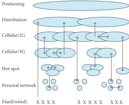
Future mobile handsets will need to support multiple wire-less communication links, potentially including 2G cellular, 3G cellular, wireless local area network (WLAN), personal-area network (PAN), broadcast, and positioning. A layered
structure of such a future network, adapted from [1], is
shown inFigure 1andTable 1.
These layers are to be integrated in a common, flexible, and seamless IP core network, supporting global roaming and a single access number per user. This requires both hor-izontal (intrasystem) and vertical (intersystem) handover, as indicated by the arrows. For each of these layers there exists a multitude of, often regional, standards. Some handheld de-vices may have to support multiple standards per layer, for example, in a world phone.
Individual standards typically evolve over the years to-wards higher bit rates, more features, and more services. For example, 3G cellular standards will need to support high-speed downlink packet access (HSDPA), and for WLAN multiple-antenna schemes are being studied (MIMO, IEEE 802.11 n).
For a given standard, new algorithms are continuously developed to improve performance (lower bit error rate,
more efficient spectrum usage). Upgrading handsets by
soft-ware would then be attractive, possibly by downloading of new software versions over the air interface.
Fixed(wired) Personal network Hot spot Cellular/3G Cellular/2G Distribution Positioning
X X X X X X X X X X X X Figure1: Layered structure of an integrated, seamless future net-work.
The combination of the above trends is sometimes re-ferred to as 3G+ or 4G wireless. They form a powerful
argu-ment for so-called software-defined radio (SDR) [1].
InSection 2we analyze the computational loads and flex-ibility requirements of the various stages of the baseband
processing of an SDR. InSection 3, a number of baseband
algorithms are analyzed in detail for execution on a vector processor. Detailed requirements for an SDR vector proces-sor are collected in passing. Based on these requirements, two
vector processors are presented inSection 4: the OnDSP,
ap-plied in WLAN products, and the EVP (embedded vector processor), being productized for 3G and beyond. Detailed load numbers for baseband kernels, including
benchmark-ing are presented inSection 5. System results for WLAN and
for UMTS are given inSection 6.
2. HW ARCHITECTURE FOR SDR BASEBAND
Estimates for the computational load (GHz) for baseband
processing are given in Figure 2, with [2] as main source.
Interestingly, the numbers roughly appear to apply to both nonoptimized programs on a Pentium 3 as well as to opti-mized (assembly) programs running on current DSPs used in GSM handsets.
The digital baseband processing for SDR can be split into three stages: a filter stage, a modem stage, and a codec stage,
as shown inFigure 3.
The loads are more or less evenly distributed across the three baseband stages. Nevertheless, the stages have very dif-ferent characteristics.
2.1. Filter stage
Various transmitter and receiver filters are required for band limitation, for example, root-raised cosine filters and sample-rate conversion. Given their high computational load (e.g., 2–5 billion multiplications and additions per second for UMTS), their regularity, and the commonality among the algorithms involved, full programmability would add
insufficient value to compensate for the additional power
consumption. A configurable multistandard filter is more ap-propriate.
2.2. Modem stage
The modem stage, sometimes called “inner transceiver” or “signal conditioner,” appears to be the most diverse across
the different standards. It includes functions such as rake
re-ception, correlation, synchronization, joint detection, equal-ization, FFT, OFDM (de)mapping, interference cancellation, and so forth. Furthermore, new modulation schemes are proposed within the ongoing evolution of standards to im-prove throughput and performance. Also manufacturers are
challenged to differentiate their products by improving
algo-rithms to reduce BERs or transmit power for the same BER. This is the stage where dBs can be gained or lost by choos-ing and optimizchoos-ing the right or wrong algorithms. This is the
stage where programmability offers most value.
2.3. Codec stage
The codec stage, sometimes called “outer transceiver” in-volves a variety of functions: (de) multiplexing, (de) punc-turing, (de) interleaving, and a variety of channel codecs (e.g., convolution, Turbo, Reed-Solomon). The performance of these functions is determined by standard algorithms,
and allows little differentiation among manufacturers. Given
the considerable similarities among standards and algo-rithms, and given the considerable processing requirements
for higher bit rates (>100 Mbps), a fully programmable
so-lution does not appear to be justifiable. See also Sections5.4
and6.
2.4. Baseband hardware architecture
The above observations on the different baseband stages
re-sult in a proposal for a multistandard hardware architecture (Figure 4), comprising:
(i) a general purpose microcontroller for link/MAC layer processing and for controlling baseband and RF tasks; (ii) a configurable filter processor;
(iii) a programmable vector processor for number crunch-ing, mostly in the modem stage;
(iv) a conventional DSP for intrinsically “scalar” algo-rithms, for example, speech codecs;
(v) one or more multistandard weakly configurable chan-nel decoders, for example, Viterbi, Turbo.
3. VECTORIZATION OF BASEBAND KERNELS
Making vector parallelism explicit in program code is com-monly called “vectorization.” Depending on the algorithm at hand, this can be relatively straightforward, or it may require some ingenuity. Unfortunately, the state-of-the-art of vector-izing compilation today cannot fully exploit the architectures
discussed inSection 4andat the same time achieveefficient
Table1: Layers of a future seamless network.
Layer Link range (log10m) Up/down Mobility Standards (examples)
Positioning 6-7 d Full GPS, Galileo
Distribution 5-6 d Full DAB, DVB-T/H
Cellular/2G 4-5 d,u Full GSM, IS95, PHS
Cellular/3G 3-4 d,u Full UMTS, CDMA2000, TD-SCDMA
Hot-spot 2-3 d,u Local 802.11 a,b,g, wifi
Personal 1-2 d,u Local Bluetooth, DECT
Fixed 0-1 d,u None POTS
802.11a UMTS GSM DVB-T GPS
Load estimates (GHz) 11n(MIMO)
HSDPA, MIMO EDGE, GPRS
Doppler compensation Galileo
0.1 0.3 1 3 10 30
Figure2: Load estimates for various SDR standards.
of acceptable efficiency for some algorithms, we rely on
man-ual vectorization for the time being. Vectorization of several key algorithms is presented below. In the sequel we assume
a vector processor that supportsP (Pa power of 2)
identi-cal operations to be executed in parallel (single-instruction multiple-data (SIMD)), as well as load (store) operations of
Padjacent values from (into) a vector memory.
3.1. Golay correlator for UMTS-FDD
In a UMTS-FDD receiver, a Golay correlator is used for initial
acquisition of a basestation signal. It is basically a filter (1)
designed specifically to detect correlation peaks of the
256-chip long primary synchronization code (PSC [3])
transmit-ted during the first 10% of each timeslot on the primary
syn-chronization subchannel (P-SCH) [4]:
y(k)=
255
n=0
PSC(255−n)×x(k−n) (1)
with PSC(i) ∈ {−1, +1}andxis one of the sample phases
of the over-sampled input stream of complex (I,Q) numbers.
The structure of PSC(i) allows a factorization of the Golay
correlator into five stages, as shown in (2). The alternative
output stagey(k) is used only during initial frequency offset
estimation.
Inputx, output y, and intermediate signals ys can be
stored in cyclic buffers of appropriate sizes. With sharing of
Control
RF/IF
D/A
A
/D
Filt
ers
Mo
d
em
Co
de
c,
(d
e)
mu
x
A
p
plication
p
ro
ce
ssing
Digital baseband
Figure3: A crude SDR architecture with the baseband section split into filters, modem, and channel codec.
subexpressions, each outputy(k) requires 13 complex
addi-tions/subtractions, 14 memory reads, and 14 memory writes (of complex values). In principle, these operations can be
ex-ecuted in parallel. However, as all operands reside in different
locations of the various buffers, the resulting parallel accesses
to memory become highly irregular, incompatible with vec-tor processing:
y1(k)=x(k−6) +x(k−4) +x(k−2)−x(k),
y2U(k)=y1(k−1) +y1(k),
y2L(k)=y1(k−1)−y1(k),
y3(k)=y2U(k−8) +y2L(k),
y4U(k)=y3(k−48) +y3(k−32) +y3(k−16)−y3(k),
y4L(k)=y3(k−48)−y3(k−32) +y3(k−16) +y3(k),
y(k)=y4U(k−192)−y4L(k−128)
+y4U(k−64) +y4L(k),
y(k)=y
4U(k−192)2−y4L(k−128)2
+y4U(k−64)2+y4L(k)2.
(2)
Vectorization of the Golay correlator becomes
rela-tively straightforward when P successive output symbols
y(k),y(k+ 1),. . .,y(k+P −1) are computed in parallel.
Memory controllerMicro- Application processing
Interconnect (Multiple)
RF trx/rcv
Configur. channel
filters
Vector
processor DSP
Configur. channel decoder
Figure4: Schematic hardware architecture for SDR/BB.
where each + (or−) operation now specifiesPcomplex
addi-tions (or subtracaddi-tions), and each reference to the data
mem-ory now specifies the load (or store) ofPadjacent complex
samples from (or to) memory. Note that, at least for the early stages, load operations from memory may be nonaligned. That is, the load address need not be an integer multiple of P.
In summary, so-called “inner-loop vectorization” of the Golay correlator is cumbersome, whereas “outer-loop vec-torization” is rather straightforward. This is typical for algo-rithms for which successive output values can be computed independently. Similar results apply to many kinds of FIR fil-ters.
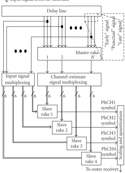
3.2. Rake receiver for UMTS-FDD
Rake receivers are commonly used for (W)CDMA, because of their ability to combine signals from multiple delay paths.
On a conceptual level (Figure 5), a UMTS rake receiver
con-sists of
(i) a delay line to compensate the various path delays,
(ii) a so-called master rake to receive the common
pi-lot channel to perform channel estimation,
frequency-offset estimation, and code tracking,
(iii) a number of so-calledslave rakesto receive the various
UMTS data channels and control channels, and (iv) a scaler and quantizer to reduce the dynamic range
be-fore entering the channel decoder.
The master rake controls the channel-dependent
parame-ters (path attenuation, phase distortion, frequency offset, and
time synchronization) of the slave rakes. Each master rake
finger includes a channel estimator, a frequency offset
es-timator, and a delay locked loop (code tracker). Using the known pilot signal, these blocks can reconstruct the path characteristics of the mobile channel.
Each slave rake (3) consists ofF rake fingers (i.e., theF
inner summations), each of which is tuned to a different
de-lay pathT−τpof the same physical channel. Each finger
per-forms the inverse function of the spreading performed by the transmitter. First, the path-dependent channel delay is com-pensated using a delay line. Then, the signal is decorrelated
with the complex conjugate of the spreading codec(k,i), and
accumulated over the same spreading factor Sused by the
Input signal from RF interface Delay line
“Early”
sig
nal
“P
unctual”
sig
n
al
“Lat
e”
sig
n
al
Master rake
1 2 N
Input signal multiplexing
Channel-estimate signal multiplexing
6 6 6 6 6 6 6 6
Slave rake 1
Slave rake 2
Slave rake 3
Slave rake 4
PhCH1 symbol PhCH2 symbol PhCH3 symbol PhCH4 symbol
Scaling
and
q
uantization
To outer receiver Figure5: UMTS rake receiver (simplified).
transmitter. These steps (called decorrelation and “integrate and dump”) are referred to as despreading. Finally, the
sig-nals of theFfingers are weighted and combined to improve
the bit error rate at the output of the slave rake:
y(k)=
F−1
p=0
w∗
p(k)× S−1
i=0
c∗(k,i)×xk·S+i+T−τ
p,
c(k,i)=cscr(k·S+i)×cch(i),
(3)
where
(i)yis the output signal (symbols),
(ii)kis the symbol time,
(iii)xis the input signal (chips),
(iv)Fis the number of delay paths (fingers),
(v)wpis the weight factor for pathp,
(vi)Sis the spreading factor,
(vii)cscris the scrambling code,
(viii)cchis the channelization code,
(ix)Tis the delay line length,
(x)τpis the delay of pathp.
Three scenarios for vectorization of the slave rake will be explored: symbol parallelism, finger parallelism, and chip parallelism.
With the symbol parallelism scenario (“block processing”
in [5])Psuccessive output symbols are computed in parallel,
(i) P different phases of the spreading-code generator
must be computed in parallel, with a distance of S
code-chips between two successive phases;
(ii) the incoming dataxmust be laid out such thatPvalues
with strideScan be read simultaneously.
Both requirements are hard to satisfy, especially if diff
er-ent rakes operate with different spreading factors. The main
problem, however, is that the latency scales withP×F×S.
This latency can become prohibitive for large S, and is
fa-tal for the UMTS fast power-control loop. For this reason,
Walther [5] proposes a combination of symbol parallelism
(for smallFand for the pilot channel) and finger parallelism
(for largeS).
With finger parallelism, min(P,F) rake fingers are
com-puted in parallel (the outer summation), one data chip
at a time. This scheme requires F different phases of the
spreading-code generator, where each phase corresponds with a path delay. The data chips are read sequentially,
re-sulting in a considerable overhead, especially for smallFand
smallS[5]. Furthermore, vector parallelism is limited toF,
and hence does not scale withP. ForF, a maximum value of
six is often quoted, but under favorable conditions lower val-ues are practical, and beneficial for low power consumption. With chip parallelism, we have arrived at the innermost
loop of (2), and we will aim at exploiting vector parallelism
within a single rake finger [6,7]. We assume for the moment
thatS=2MPfor some integerM. The spreading-code
gen-erator now has to producePsuccessive code chips in parallel.
Unlike the rake solutions based on finger and symbol
paral-lelism, the code generator must alsoleapbyP symbols at a
time. A solution with a high throughput (300 MHz), and a
low set-up time (few clock cycles) is described in [8]. With
the input sample phases separated in memory,Pdata chips
can be read in parallel as adjacent, nonaligned complex sam-ples.
Since the active fingers are processed sequentially, the
processor load is proportional toF. Furthermore, chip
par-allelism scales well withP, that is, a wider data path yields a
proportionally lower load. The latency is determined by the
number of symbolsKprocessed in the inner loop of the
algo-rithm. For example, withK×Sbounded to 512 chips, the
re-sulting latency can comfortably accommodate UMTS power control.
Unlike symbol and finger parallelism, chip parallelism re-quires so-called intravector addition. That is, the inner
sum-mation of (3) must support the summation ofP complex
values in a single instruction [6]. The caseS < Pis identical,
except that the intravector addition producesP/Ssymbols.
3.3. Symbol-timing estimation for 802.11a
The symbol-timing estimation, also referred to as clear
channel assessment (CCA), incorporates a rough
symbol-timing estimation procedure in the 802.11a WLAN stan-dard. It serves as a final preamble indicator by detecting the transition between the short and the long symbol field.
If an 802.11a preamble is confirmed, fine symbol-timing
estimation is performed on the long symbol portion by
frequency-domain processing [9]. Below, we address the
rough symbol estimation.
The rough symbol-timing estimator performs two tasks: (1) it indicates the presence of an 802.11a preamble by de-tecting its unique transition from a short symbol se-quence to a long symbol sese-quence,
(2) it estimates the start of the long symbol field with an
accuracy of±31 samples.
Based on extensive simulation it was chosen to base the es-timation on the calculation of two sliding vector products, called autocorrelator functions (ACFs). The ACFs are com-pared by a threshold, which avoids division. The first ACF
calledacf16tracks the end of the short symbol field
accord-ing to the metrics:
A16(k)= k
i=k−31
r∗(i)r(i−16), (4)
P32(k)= k
i=k−31
r(i)2. (5)
Those can be iterated as
A16(k)=A16(k−1) +r∗(k)r(k−16)−r∗(k−32)r(k−48), (6) P32(k)=P32(k−1) +r(k)2−r(k−32)2. (7)
Their combination yields the detection indicator
I16(k)=A16(k) 2
−TlP32(k)P32(k−16), (8) ˆ
k64=min
k|I64(k)>0
, (9)
where the value ofTldepends on the SNR. A short symbol
field has a period of 16 samples, and hence also of 64 samples.
To remove this ambiguity,I16(k) is calculated. IfI16(k)<0,
that is, there is no autocorrelation with a period of 16, the computation of a similar ACF is started to detect the begin-ning of the long symbol field with a period of 64.
Outer-loop vectorization, that is, computingPoutputs in
parallel, can be applied toacf16(5), to power computation
(7), and to the detection indicator (8). The minimum value
of this indicator ˆk16, its indexk, and the break condition (9)
have to be computed sequentially. This can be done on the
fly, that is,in parallelwith the vector operations above.
3.4. Fast Fourier transform
The FFT is one of the fundamental DSP algorithms. Together with its inverse, it is a key algorithm for OFDM standards
such as 802.11a (cf.Section 6.1). The basic computation of a
radix-2 FFT is the butterfly applied to pairs of complex
sam-ples, say, 2×12 bits:
y0=x0+ω×x1,
y1=x0−ω×x1,
whereωis a complex root of unity. AnN=2npoint FFT is
generally organized as a cascade ofnstages each comprising
N/2 butterflies. On a vector processor, a group ofP/2
but-terflies can be computed in parallel conveniently, assuming
N≥2P. Depending on the particular FFT algorithm and on
the stage, the two input vectors of such a group can be plain
output vectors of different groups of the preceding stage, or
permutations thereof. Such permutations (a.k.a. vector shuf-fles) must be supported in an SDR vector processor.
Most FFT algorithms require a presorted input block, or require some postsorting of the output block (bit-reversal or
digit reversal). So-called self-sorting FFTs [10] avoid this, and
can lead to particularly efficient vectorized FFT solutions.
3.5. Viterbi decoding
Viterbi decoders are probably the most common channel de-coders for convolutional codes. They are rather computa-tionally intensive and comprise two distinct types of com-putation: trellis construction and trace back. Trellis construc-tion allows fairly straightforward vectorizaconstruc-tion, assuming the availability of vector permutations, similar to those used for FFT. Trace back, however, is inherently sequential, requiring scalar read accesses into the trellis stored in the vector mem-ory.
For small constraint lengths of the convolutional code,
or for largeP, trace back tends to take more time than
trel-lis construction. In practice, the two may well be in balance. Hence, ideally, both types of computation can be scheduled in parallel on the vector and scalar parts of a vector processor
[11].
3.6. SDR vector processor requirements
From the vectorized baseband kernels above we can now col-lect the requirements for an SDR vector processor.
(R1) In addition to the 16-bit data types common for DSPs, 8-bit data types are useful for the incoming radio sig-nals. They allow a higher memory density, and twice the parallelism in the SIMD data path. Support for complex arithmetic will benefit all presented kernels, except the Viterbi decoder.
(R2) Vectorization of most presented algorithms scale well
withP. In practice, a limit will occur for 64 complex
samples for the 802.11a algorithms. As shown later on, a much narrower machine will cover many of today’s standards. In order to be prepared for future evolution, including multitasking, it is valuable to keep the vector
processorscalable, that is, to parameterize its
architec-ture and its implementation (including tools) byP.
(R3) Orthogonal to pure SIMD parallelism, VLIW (very
long instruction word [12]) parallelism can further
ac-celerate the rake (pipelined memory access + code
gen-eration + decorrelation + integration,Section 3.2) as
well as the FFT (a pipelined multiply + add/subtract + shuffle,Section 3.4).
(R4) The speed-up that can be achieved by combining vec-tor and VLIW parallelism is limited by the fraction of
the program code that can be vectorized. This
limi-tation is known as Amdahl’s law [12]. For example,
when 90% of an algorithm can be sped up by a
fac-torP = 32, the overall speed-up is less than a
fac-tor eight! In order to counter this limitation, a
par-allel speed-up isalsorequired for the nonvectorizable
parts of an algorithm. Examples of the latter were the minimum/index calculations of the symbol-timing
es-timator (Section 3.3) and the trace-back function of
the Viterbi decoder (Section 3.5). To further counter
Amdahl’s Law, parallel address calculations and loop control are critical, even more so than for traditional
DSPs [13].
(R5) Beyond “pure” SIMD, shuffling of data within a vector
[14] is key to both FFT (Section 3.4), and Viterbi trellis
construction (Section 3.5). Furthermore, such a
shuf-fle operation can support vector rotation, which can be used to implement nonaligned read access to vector memory as required, for example, for Golay
correla-tion (Section 3.1) and rake reception (Section 3.2).
(R6) Also intravector operations (a.k.a. vector reductions) are important, for example, for rake integration (Section 3.2).
(R7) A useful, but rather CDMA-specific capability is the
“generate the nextPsuccessive code chips” instruction
for a variety of composite codes.
(R8) As we aim at handheld devices, small silicon area (in-cluding data and program memories) is essential, as well as low power consumption.
(R9) The processor must be conveniently programmable,
supported by effective and efficient tools.
Note that (R2), (R3), and (R4) deal with computational
per-formance (effectivenumber of operations per second), and
that (R5), (R6), and (R7) deal with functional capabilities.
4. VECTOR PROCESSORS: OnDSP AND EVP
As we have seen inSection 3, vector processing can be used
to exploit the abundant and often regular parallelism en-countered in many baseband algorithms. Using SIMD in-structions (single-instruction multiple-data) arithmetic
op-erations or load/store opop-erations can be applied toP (e.g.,
P=16) samples in parallel.
The basic features of a vector-processor suitable for SDR
are listed below, with reference toFigure 6and the
require-ments ofSection 3.6(Rn).
(i) The dominant data size is 16 bits as in conventional DSPs, with some support for 8-bit and 32-bit data.
Hence a single SIMD vector comprisesP 16-bit
ele-ments, 2P 8-bit elements, orP/2 elements of 32 bits.
Accumulator registers have extension bits to support high-resolution accumulation. The main data types are integer and fixed point, with support for complex
numbers (2×8 or 2×16 bits) (R1).
(ii) The vector memory supports one vector read or vector
Pro gr am m em o ry VLIW co nt ro ller AC U · · · · · · Vector FU Vector register file
Vector memory
Pwords wide 1 word wide
Scalar RF
Scalar FU Figure6: A generic vector-processor architecture.
Pro gr am m em o ry VLIW co nt ro ller AC U
8 words wide 1 word wide
· · · · · · Vector memory
4 vector registers Load/store
ALU MAC Shift
4 scalar regs. Load/store
ALU MAC Shift Figure7: The OnDSP architecture.
(iii) The VLIW execution model supports parallelism among multiple vector functional units (FUs), for
ex-ample, MAC, ALU. This VLIW parallelism comesin
addition tovector parallelism (R3).
(iv) On top of thata VLIW instruction mayalsospecify sev-eral operations on scalar functional units (R4). (v) To keep many functional units busy, there is
ex-tensive support for address calculations (ACUs, e.g., postincrement, modulo) and for zero-overhead loop-ing (R4).
Compared to other programmable architectures, SIMD ex-ecution results in low power consumption (R8), because the “overhead” of address calculations, address decoding,
in-struction fetching/decoding, and control is shared byP
oper-ations. A similar reasoning holds for silicon area per MOPS. With the above in common, two vector processor in-stances have been developed within Philips: OnDSP targeting WLAN, and EVP targeting 3G and beyond.
4.1. OnDSP
The OnDSP vector processor is a key component of several multistandard programmable wireless LAN baseband
prod-uct ICs [15]. The application of vector processing to WLAN
will be addressed inSection 6.1.
The OnDSP architecture is depicted in Figure 7. The
vector size equals P = 8 (128 bits). A single VLIW
in-struction can specify a number of vector operations, for example, load/store, ALU, MAC, address calculations, and
Pro gr am m em o ry VLIW co nt ro ller AC U
16 words wide 1 word wide
· · · · · · Vector memory
16 vector registers Load/store unit
ALU MAC/shift unit
Shuffle unit Intravector unit Code generation unit
32 scalar regs. Load/store U
ALU MAC U
AXU Figure8: The EVP architecture.
loop-control ((R3), (R4)). OnDSP supports a couple of spe-cific vector instructions, including word insertion/deletion, sliding, and gray coding/decoding. Data addresses must be
a multiple of P. Program code is compressed vertically
(“tagged VLIW” [16]).
In a 0.12µm CMOS process, OnDSP measures about
1.5 mm2 (250 kgates), runs 160 MHz (worst-case
commer-cial), and dissipates about 0.8 mW/MHz including a typical memory configuration (R8). A macroassembler is used for VLIW scheduling, although optimization by hand is used for critical code.
4.2. EVP
The EVP (embedded vector processor) is a productized
ver-sion of the CVP [7]. Although originally developed to
sup-port 3G standards, the current architecture proves to be highly versatile. Care has been taken to cover the OnDSP ca-pabilities for OFDM standards.
The EVP architecture is depicted inFigure 8. The main
word width is 16 bits, with support for 8-bit and 32-bit data (R1). The EVP supports multiple data types, including com-plex numbers (R1). For example, a comcom-plex vector
multipli-cation usesPmultipliers to multiply 1/2pcomplex numbers
each two clock cycles.
The SIMD width is scalable (R2), and has been set to
P = 16 (256 bits) for the first product instance EVP16. The
maximum VLIW-parallelism available equals five vector
op-erations plusfour scalar operations plusthree address
up-datesplusloop-control. Specific FUs of the EVP include the
following ((R3), (R4)).
(i) The shuffle unit can be used to rearrange the elements
of a single vector according to an arbitrary pattern (R5).
(ii) The intravector unit supports operations such as add (or take the maximum of) the elements of a single
vec-tor, possibly split in,Msegments ofP/Melements each
Table2: Load (MHz) of a UMTS-FDD rake finger.
Processor Ref. Load (MHz) Arithmetic resources (complex arithmetic)
EVP16 [7] 0.5 16×(MAC+ ALU + PN gen.)
Tigersharc [6] 1 2×8×(MAC+ ALU)
4 UMTS DP [18] 6 4×(MAC+ ALU + PN gen.)
UMTS DP [18] 25 1×(MAC+ ALU + PN gen.)
TI C62 [19] 40 –
Carmel [18] 125 2 MAC + ALU
TI C54x [18] 300 1 MAC/ALU
(iii) The code generation unit supports CDMA-code gen-eration: in a single clock cycle 16 successive complex code chips are generated (R7). The unit can be config-ured for a variety of codes (UMTS, CDMA2000, GPS, etc.) and for cyclic redundancy checks (CRC).
In a 90 nm CMOS process, the EVP16 core measures about
2 mm2 (450 kgates), runs 300 MHz (worst-case
commer-cial), and dissipates about 0.5 mW/MHz (core only) and 1 mW/MHz including a typical memory configuration (R8). These numbers are based on gate-level simulations of anno-tated netlists.
Programs are written in EVP-C, a superset of ANSI-C. Programs written in plain C will be mapped on the scalar part of the EVP, and hence will not utilize the vector FUs. The extensions include vector data types and function intrin-sics for vector operations, all in a C-like syntax. The EVP-C compiler takes care of register allocation (scalar and vector registers) as well as VLIW instruction scheduling (scalar and vector operations combined). The EVP tool flow (R9) fur-ther comprises an EVP-C host-emulation library, a linker, a bit-true/cycle-true simulator, a profiler, and an integrated de-bugger.
5. RESULTS FOR BASEBAND KERNELS
The results of mapping the baseband kernels of Section 3
onto the vector processors ofSection 4are presented below,
together with relevant benchmarking. 5.1. Golay correlator for UMTS-FDD
On the EVP16as many as 1/2p=8 complex additions/
sub-tractions (2×16 bit) can be computed in parallel. Automatic
scheduling of the EVP-C version of the Golay correlator on
the EVP16requires 22 cycles for 1/2psymbols. Manual
opti-mization of the memory accesses and schedule reduces this to
16 cycles for 1/2psymbols. Note that the 16 adders are busy
for 13/16 of the time (Section 3.1). Assuming correlation on
two sample phases of 4 MHz each, the EVP16 load becomes
2×4.106×16 cycles /(1/2p=8), or approximately 16 MHz.
5.2. Rake receiver for UMTS-FDD
On the EVP the inner loop of the rake (Section 3.2) keeps
most FUs busy. A single EVP VLIW instruction (1/ fc
throughput) specifies
(i) load and align a sample vector ofPdata chips,
(ii) auto increment byPof the pointer to these chips,
(iii) generate a vector of the nextPcode chips,
(iv) correlate a vector of data and a vector of code chips,
(v) intra-add result to one or few symbols (S≤ P) or to
one partial symbol (S > P).
For the UMTS-FDD chip rate of 3.84 MHz this implies an
EVP16load of about 0.3 MHz per rake finger for the chip-rate
processing (3), including loop preambles and postambles for
blocks of 512 chips. Including some symbol-rate processing this will increase to 0.4-0.5 MHz, depending on the spreading factor.
Table 2summarizes the load (MHz) of a rake finger on various programmable DSPs.
5.3. Fast Fourier transform
Both OnDSP and EVP exploit pipeline parallelism (imple-mented by means of VLIW) among
(i) a complex vector multiplication, (ii) a vector addition/subtraction, and
(iii) a vector permutation (between the butterfly stages).
For a complete 64-point FFT, the OnDSP and EVP16require
160 and 64 cycles, respectively, based on manually scheduled code. Normalized on the respective processor SIMD widths
(P = 8 and P = 16), EVP16 is somewhat faster because
its add/subtract instruction allows implicit scaling between
stages. Note that all 16 EVP16’s multipliers are active during
48/64 clock cycles!
The prototype EVP-C compiler requires 79 cycles, about 25% more than the hand-scheduled assembly code.
Table 3shows the cycle counts for a 64-point FFT (incl.
bit-reversal) for a number of DSPs. The numbers from [17]
have been scaled from a 256-point FFT in proportion to the number of butterflies. The column “code” specifies whether the program has been compiled “out-of-the-box”, that is, without any manual intervention, or whether it has been hand optimized at the assembly level.
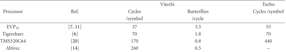
5.4. Viterbi and turbo decoding
Table3: Cycle counts for a 64-point FFT.
Processor Ref. Code Clock cycles SIMD
EVP16 – Optimized 64 16×16
OnDSP – Optimized 160 8×16
Tigersharc [6] Optimized 174 2×8×16
VIRAM – Optimized 357 16×32
TMS320C6203 [17] Optimized 646 N.A.
Altivec MPC7447 [17] Optimized 956 8×16
Carmel 10xx [17] Out-of-the-box 5568 N.A.
AMD K6-2E+/ACR [17] Out-of-the-box 10 751 N.A.
Table4: Viterbi and turbo decoding on several DSPs.
Viterbi Turbo
Processor Ref. Cycles Butterflies Cycles /symbol
/symbol /cycle
EVP16 [7,11] 37 3.5 55
Tigersharc [6] 70 1.8 70
TMS320C64 [20] 170 0.8 440
Altivec [14] 260 0.5 –
AMR voice channel (constraint lengthK =9). The 3.5
but-terfly operations/clock cycle for EVP16 translates to 10
cy-cles/symbol for a decoder with constraint length 7.
Table 4also provides load numbers for turbo decoding
(3 GPP, with 6 iterations). The EVP16cycle count is an
esti-mate, based on hand schedules.
6. SDR RESULTS
In the preceding sections we have presented a vector-processor architecture for SDR using several baseband algo-rithms from the UMTS and WLAN domain as drivers. In
ad-dition to its efficiency for isolated algorithms, the resulting
architecture (cf.Figure 4) needs to be assessed in an overall
system context.
6.1. Wireless LAN
The Philips 802.11 a,b,g baseband implementation (product
SA250) is based on the OnDSP vector processor [15]. Below
we focus on the IEEE 802.11a standard. From Section 5.4,
we can conclude that for the symbol rates at hand (up
to 54 MHz) it is not practical to map Viterbi decoding
on a vector processor. Hence, the OnDSP is employed for (de)modulation tasks, while hardware accelerators support Viterbi decoding, (de)interleaving, and de(scrambling). The main tasks for the vector processor are
(i) preparing transmission data (TX),
(ii) equalizing and tracking when receiving data (RX), (iii) burst detection and acquisition.
The OnDSP cycle counts ofTable 5yield an OnDSP load of
110 MHz. For the EVP16, with twice the parallelism, this will
go down to approximately 55 MHz. In addition to meeting the OnDSP load constraint, the OnDSP can also cope with the tight real-time constraints for synchronization.
Interestingly, software flexibility doesnotincrease the
sil-icon area for this application. Unlike, for example, [21], the
same hardware is used for synchronization and FFT.
6.2. UMTS-FDD
Today’s GSM handsets deploy programmable DSPs for all baseband signal processing, with all the associated flexibility benefits. Moreover, it has allowed concurrent and indepen-dent evolution of DSP architectures (following Moore’s law)
and algorithmic improvement. Different groups of designers,
often in different companies used the DSP architecture and
tools as interface between them.
For 3G standards, such as UMTS, this is not entirely
prac-tical, at least for the time being. FromSection 5.4we can see
that Turbo decoding alone requires about 55 clock cycles per
symbol on the EVP16. For UMTS 3 GPP R’99 this results in
an acceptable 35 MHz load for a 640 kbps channel. For 3GPP release 5, however, a 14 Mbps data rate would result in an
EVP16load in excess of 700 MHz, and a power consumption
close to 1 watt in 90 nm CMOS. Accordingly, we choose the
architecture ofFigure 4. This hardware-software partitioning
is markedly different from [22], where all channel (de)
cod-ing is also mapped on DSP software.
Furthermore, 3G+ standards show a much more dy-namic computational load than 2G standards, both due to the nature of the employed algorithms and the large number
of different use cases. This can be illustrated for four UMTS
scenarios [3].
Table5: OnDSP load for the critical loop of the 802.11a (de)modulator (cycles per OFDM symbol of 4 microseconds).
OnDSP load (de)modulator task TX (cycles) RX (cycles)
Symbol (de)mapping 35 35
Pilot generation 55 –
Pre (post) scaling 35 35
Tracking – 36
Channel correction – 39
OFDM (de)mapping 35 35
Afc(I) FFT 160 160
TS frequency shift 40 –
Phase-error correction – 39
CP insertion/removal 35 –
Control code 40 40
Overall peak load 435 414
Overall peak load (Mhz) 109 104
Table6: EVP16loads for the modem stage; 4 scenarios.
EVP16load (MHz)
UMTS task 1 2 3 4
PSCH search (Golay) 18 18 18 18
CPICH search 98 17 17 17
CPICH despreading – 4 22 33
CPICH symbol rate – 1 1 2
DCH despreading – 3 16 16
DCH symbol rate – 1 6 6
HS-SCCH despreading – – – 15
HS-SCCH symbol rate – – – 1
HS-DSCH despreading – – – 12
HS-DSCH symbol rate – – – 22
Overall peak load 116 44 80 142
Overall average load 4 28 64 126
(2) UMTS R’99 connected mode with flat fading con-ditions (1 rake finger only), 3 dedicated channels (DCH), and neighbor-cell broadcast channel (BCH) monitoring.
(3) UMTS R’99 connected mode in a scattering environ-ment with multiple paths (six rake fingers) with the same transport channel configuration as before. (4) UMTS R’99 connected mode in a scattering
environ-ment with multiple paths (six rake fingers) with the same transport channel configuration plus an HSDPA (high speed downlink packet access) link (3GPP R5) with 15 downlink channelization codes.
The EVP16 load numbers for these four scenarios, based on
simulation of kernels, are summarized in Table 6. Note the
variation in load distributions! More advanced receiver algo-rithms such as interference cancellation, chip-rate equaliza-tion, or joint detection will be required in the future, both to increase the system capacity and to improve the reception
quality. This is, from our point of view, one of the most com-pelling justifications for SDR.
6.3. Multistandard considerations
EVP16load numbers for the modem stage for various
wire-less standards are shown inFigure 9. Note the considerable
headroom available on EVP16for most standards.
The available headroom can be used to
(i) introduce improved but more demanding algorithms, (ii) scale the supply voltage to reduce power consumption,
and, in principle,
(iii) run multiple standards simultaneously.
The latter introduces intrastandard resource sharing, substantially reducing the additional costs for adding a radio standard. For the combination of WLAN and UMTS,
includ-ing intersystem handover, this is illustrated inFigure 10.
802.11a UMTS GSM DVB-T GPS
EVP (MHz)
11n(MIMO) HSDPA
EDGE
Doppler compensation Galileo
50 100 150 200 250 300
EVP in 90 nm CMOS
Figure9: Estimated EVP16load numbers for the modem stage of various receivers.
25 55 75 100 125 MHz
Initial acquisition
UMTS connected
UMTS connected/ WLAN acquisition
WLAN connected/ UMTS monitoring P-S
CP
ICH
sear
ch
P-S P-S
CPICH search Rake chip-rate processing Rake sym-rate proc.
P-S P-S
CPICH search Rake chip-rate processing Rake sym-rate proc.
WLAN acquisition
Intersystem handover
P-S P-S
CPICH search WLAN receiver
Time
Figure10: Handover from UMTS to WLAN, with load indications for the EVP16. P-S=PSCH search.
7. CONCLUSION
The modem stage of an SDR requires software flexibility to cope with the multitude of wireless standards, their evolu-tion, and with algorithmic improvement (including bug fixes and in-field upgrades) without the need to respin an IC.
Vec-tor parallelism in combination with VLIW can offer the
com-putation power required for this. The OnDSP has
demon-strated this for several WLAN ICs. The EVP16, with its
pow-erful FUs (shuffle, intravector, code generation) outperforms
conventional DSPs by an order of magnitude or more, in
a power-efficient way. Accordingly, the EVP16 can be a key
component of an SDR, where it can save silicon area by both intrastandard and interstandard reuse. With 300 MHz, the
EVP16can potentially handle multiple standards
simultane-ously.
ACKNOWLEDGMENT
The contributions of Srinivasan Balakrishnan, Nur Engin, Rick Nas, and Rob Takken (all with Philips Research Labs), and of Wim Kloosterhuis, Jean Paul Smeets, and Mahima Smriti (all with Philips Semiconductors) are gratefully ac-knowledged.
REFERENCES
[1] R. Becher, M. Dillinger, M. Haardt, and W. Mohr, “Broad-band wireless access and future communication networks,” Proc. IEEE, vol. 89, no. 1, pp. 58–75, 2001.
[2] R. Kokozinski, D. Greifendorf, J. Stammen, and P. Jung, “The evolution of hardware platforms for mobile ‘software de-fined radio’ terminals,” inProc. IEEE 13th International Sym-posium on Personal, Indoor and Mobile Radio Communica-tions (PIMRC ’02), vol. 5, pp. 2389–2393, Lisbon, Portugal, September 2002.
[3] 3GPP TS 25.211, “Physical channels and mapping of trans-port channels onto physical channels (FDD) - (Release 5),” v. 5.5.0 (2003-09).
[4] 3GPP TS 25.213, “Spreading and modulation (FDD) - (Re-lease 5),” v. 5.5.0 (2003-12).
[5] U. Walther, “Signalprozessorarchitecturen f¨ur den Mobilfunk der 3. Generation,” Ph.D. Dissertation, Technische Universit¨at Dresden, Germany, 2002.
[6] J. Fridman and Z. Greenfield, “The TigerSHARC DSP archi-tecture,”IEEE Micro, vol. 20, no. 1, pp. 66–76, 2000.
[7] K. van Berkel, P. P. E. Meuwissen, N. Engin, and S. Balakr-ishnan, “CVP: a programmable Co vector processor for 3G mobile baseband processing,” inProc. World Wireless Congress (WWC ’03), San Francisco, Calif, USA, May 2003.
[9] B. Stantchev,An approach to synchronized detection in DFT-based receivers, Ph.D. thesis, Shaker Verlag, Aachen, Germany, 2002.
[10] F. Arguello, J. D. Bruguera, and E. L. Zapata, “A parallel archi-tecture for the self-sorting FFT algorithm,”Journal of Parallel and Distributed Computing, vol. 31, no. 1, pp. 88–97, 1995. [11] N. Engin and K. van Berkel, “Viterbi decoding on a
coproces-sor architecture with vector parallelism,” inProc. IEEE Work-shop on Signal Processing Systems (SIPS ’03), pp. 334–339, Seoul, Korea, August 2003.
[12] J. L. Hennessy and D. A. Patterson, Computer Architecture: A Quantitative Approach, Morgan Kaufmann, San Francisco, Calif, USA, 3rd edition, 2003.
[13] P. Lapsley, J. Bier, A. Shoham, and E. A. Lee,DSP Proces-sor Fundamentals: Architectures and Features, Berkeley Design Technology, Fremont, Calif, USA, 1994–1996.
[14] L. Gwennap, “G4 is first PowerPC with altivec,” in Micropro-cessor Rep., pp. 17–19, November 1998.
[15] J. Kneip, M. Weiss, W. Drescher, et al., “Single chip pro-grammable baseband ASSP for 5 GHz wireless LAN appli-cations,”IEICE Transactions on Electronics, vol. E85-C, no. 2, pp. 359–367, 2002.
[16] M. Weiss and G. P. Fettweis, “Dynamic codewidth reduction for VLIW instruction set architectures in digital signal pro-cessors,” inProc. 3rd International Workshop on Signal and Image Processing (IWSIP ’96), pp. 517–520, Manchester, UK, November 1996.
[17] Embedded Microprocessor Benchmark Consortium.http:// www.eembc.com/.
[18] U. Walther, F. Tischer, and G. P. Fettweis, “New DSPs for next generation mobile communications,” inProc. Global Telecom-munications Conference (GLOBECOM ’99), vol. 5, pp. 2615– 2619, Rio de Janeireo, Brazil, December 1999.
[19] P. R. Dent, “W-CDMA reception with a DSP based soft-ware radio,” inProc. 1st International Conference on 3G Mo-bile Communication Technologies, pp. 311–315, London, UK, March 2000.
[20] T. Horner and J. Nikolic-Popovic, “Application of TMS320-C6400 in 3G Wireless Infrastructure Transceiver,” 2000,
http://focus.ti.com/pdfs/univ/01-Wireless.pdf.
[21] T. H. Meng, B. McFarland, D. Su, and J. Thomson, “Design and implementation of an all-CMOS 802.11a wireless LAN chipset,”IEEE Commun. Mag., vol. 41, no. 8, pp. 160–168, 2003.
[22] J. Glossner, D. Iancu, J. Lu, E. Hokenek, and M. Moudgill, “A software-defined communications baseband design,”IEEE Commun. Mag., vol. 41, no. 1, pp. 120–128, 2003.
Kees van Berkel is a Fellow at Philips Research Laboratories, Eindhoven. He re-ceived an M.S. degree (cum laude) in elec-trical engineering from the Delft Univer-sity of Technology in 1980 and a Ph.D. de-gree in 1992 from the Technical University Eindhoven (TU/e). Since 1996, he has been a Visiting Professor at the Department of Mathematics and Computer Science, Tech-nical University Eindhoven (TU/e). From
1986 until 2000, he led the team that pioneered the synthesis, test, and application of asynchronous VLSI circuits based on hand-shake circuits. He contributed more than 25 scientific publica-tions, 7 patents, and the bookHandshake Circuits. Today, these cir-cuits find application in ICs for pagers, corded phones, contactless smartcards, controllers, and more. During the late 1990s, his re-search focus moved to architectures for mobile wireless terminals.
He initiated and coarchitected the CVP, the predecessor of the EVP. His current research interests include software-defined radio, signal processing algorithms, vector processing, VLSI architectures, DSP architectures, memory architectures, and interconnect-centric de-vice architectures.
Frank Heinlewas born in 1968. He received his Dipl.-Ing. (M.S.) degree and Dr.-Ing. (Ph.D.) degree from the University of Er-langen, Germany, in 1994 and 1998, respec-tively. From 1994 to 1997, he was work-ing as a Research Assistant at the University of Erlangen on multirate signal processing. Since 1997, he has been with Philips Semi-conductors, Nuernberg, Germany, working on signal processing and baseband
architec-tures for various mobile communication systems including IS-136, UMTS, and TD-SCDMA. His research interests include mobile communications, software-defined radio, signal processing algo-rithms and architectures.
Patrick P. E. Meuwissenreceived his M.S. degree in information technological science from the Faculty of Electrical Engineering, Technical University Eindhoven (TU/e) in 1997. Currently, he is a Senior Scientist in the Embedded Systems Architectures on Silicon Group, Philips Research Laborato-ries, Eindhoven, The Netherlands. There, he coarchitected the CVP, the predecessor of the EVP. He was also heavily involved in the
creation of the initial CVP tools, and used these to perform the first algorithm mapping experiments. In February 2005, he completed his studies at the Philips Research “Architecture School.” His cur-rent research interests include system architecture, embedded sys-tem design, hardware-software codesign, and VLSI syssys-tems for new multimedia applications like 3DTV.
Kees Moerman is currently working as Chief Architect in the DSP Innovation Cen-ter, Philips Semiconductors. As such, he is responsible for the technical roadmap of the DSP cores as used in, for example, the Nex-peria Mobile architecture, including “classi-cal” DSP cores as reacquired from Adelante Technologies, and the new vector process-ing core architecture as described in this pa-per. Before joining Philips Semiconductors
in 1995, he worked for 10 years at Pijnenburg Micro-electronics BV, The Netherlands, on the design of embedded microcontroller and DSP cores, and the corresponding software development envi-ronments and tools. He holds an M.S. degree in physics and infor-mation technology which he received from the Utrecht University, The Netherlands, and has 15+ years of experience in DSP architec-ture and design.