Review on Wind Energy Conversion at
Variable Speed
Komal P.Hole
1, Dr.V.N.Ghate
2,Prof.S.H.Thakare
3M.E Scholar, Dept. of Electrical Engg, VBKCOE Malkapur, India1 Associate. Professor, Dept. of Electrical Engg, GCOE Amaravati, India2
Asst. Professor, Dept. of Electrical Engg, VBKCOE Malkapur , India3
ABSTRACT:Recently we observe that electricity is use in tremendous manner so that the statistical data deals with the DFIG which is based with the turbine of the wind having the fluctuating nature .so, it occurs the change in speed & variable pitch control .it is the common turbine in the developing wind market. We know that the fuel cell is the new technique or way for energy saving that has the potential to complete with the other conventional system facilities. In various generation & distributed sectors the fuel cell acts as the potential source for the electricity because fuel cells easy to handled. The wind having fluctuating nature so, the dynamic model of SOFC is combined the wind turbine for reliable and proper enough operation. In that we have to use the bi-directional power flow convertor. which is derived from the speed above and below of synchronous speed. The fuel cell having priority in market because it having higher efficiency, cleanliness and cost-effective. So that it having grate demand in from the utility. A dynamic model of SOFC based fuel cell using the Nernst equation and variable load is can be analysis and simulated for that conversion system is block with the DFIG and two back-to-back PWM Insulated Gate Bipolar Transistors (IGBTs) with voltage source converters in rotor circuit all is based with vector control technique.
KEYWORDS: -SOFC (Solid Oxide Fuel Cell), WECS (wind Energy Conversion System), DFIG (Doubly-Fed
Induction Generator), PWM (Pulse Width Modulation)
I.INTRODUCTION
II. OPERATING MECHANISM
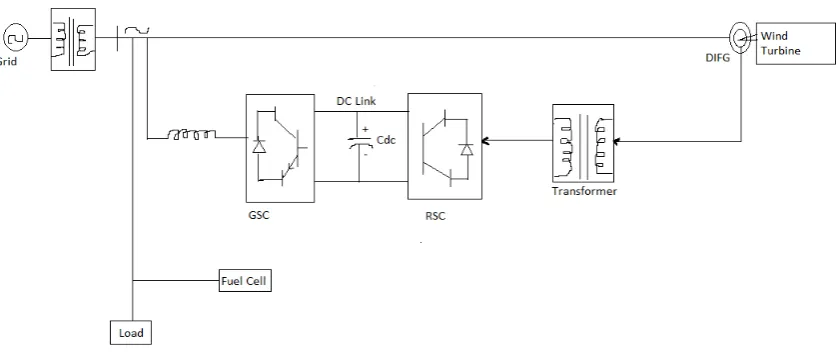
Firstly, we have studied about the mechanism which having the major components these all are included in the operating mechanism of system. The stator is connected with AC main and rotor(Wound) is driven from the electronics convers through the slip ring which is allow DIFG to get works at the fluctuating nature of wind which gives their response at the variable speed while occurring this process the frequency of the grid voltage is should maintained fixd with wind speed with the help of back –to-back convertors .
Fig 1 :- DIFG – Fuel cell test system with Simulink configuration
The stator gives there response at the two stage such as sub – synchronous speed and super synchronous speed. at the sub –synchronous speed the stator is generate the power but some power fed to rotor. and second at super-synchronous speed both components i.e. stator and rotor are generating the power to the grid. This show the bi-directional power flow means view like to rotor from supply and form supply to the rotor so due that operation the speed of machine or the motor can be maintained and controlled from either rotor or from the stator side convertor in both two cases i.e. sub-synchronous and super-synchronous speed rage. This can be clear that the machine can controlled by helping the generator or motor in two cases of synchronizing working modes. The construction and the working of fuel cell are same like battery but there is only one exception that fuel cell can be continuously fed to the cell.[10,11]
The components are as follows: A. Wind turbine
B. Doubly fed induction generator C. Fuel cell
D. Simulation of DIFG-SOFC grid test system Now we have to study the above component
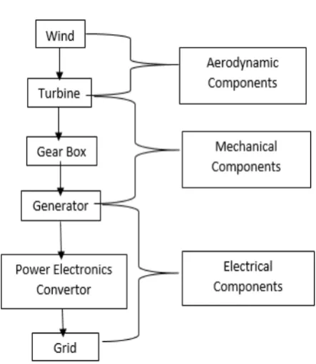
Fig 2:-Block Diagram of Components of WECs connected to grid
From diagram (2) the working information conveys that the wind is passes through turbine blades generating blades generating lift and also the tuning force .The all procedure shows that the rotating blades of mill turn into shaft inside the nacelle which enters into a gearbox , The rotational speed increases the level which is suitable for the generator , these can be uses the magnetic fields to rotational energy into the electrical energy, Here some wind turbines topologies are given:-constant speed turbine i.. type A and changing speed turbine ,Type B turbine which are soft starter , Type C turbine which is doubly fed induction generator with partial convertor , Type D turbine . In that Type C is operate at partial scale while Type D at full scale. The partial scale frequency works the reactive power compensation and the smoother grid connection. it having vast range in dynamic speed control [1,2]
Doubly fed induction generator: - It consists of the parameters like: -
1.D-Q theory: -
D-Q theory is the reference frame theory it the concept derived by Park He transformed stator variables to the rotating reference frame which is fixed in rotor. [2]
2.DIFG Constructional view and vector control method principle: -
The DIFG having basic components are DIFG (wound rotor type induction machine), PWM voltage source converters, Utility grid, PI controller
.
Vector control this can be used on the suitable control action t has the main role in the unit vector is to convert the 2-phase model to 3-phase model. This method explains two axes for representation. Principle involved the following parameters
i)Rotor Side convertor(RSC): -The main goal of the machine side converter is to maintain the rotor speed constant irrespective to the speed of wind it having controlled by the two axes of active and reactive power. [5]
In that case the the idr and iqr are with the reference rotor currents i*rd and i*rq which is produces the signals from the
side of rotor converter.
Vdr*=Vdr’+ Rridr - (ωe-ωr) [Lriqr+Lmiqs] ... (1)
Vqr*=Vqr’+Rriqr+ (ωe-ωr) [Lridr+Lmids]...(2)
Where, Vdr and Vqr get from the error sorting procedure by PI controllers. [5]
ii)Grid Side Converters(GSC): -The main purpose of GSC to maintain the DC-link constant i.e. Voltage for the necessary action. this vector control technique is basically composed for to solving the fluctuating voltage problems.
In that we are observing below synchronous speed the converters is acts as the rectifier and in opposite condition acts as the inverter to supply all producing power to the grid at the DC link voltage.
GSC is to maintain the dc-link voltage constant so that vector controlling technique is suitable for the control of GSC the PWM converter is the regulating device with two axes parameters i.e. idr and iqr we can elaborate the power
factor operation by set reactive power demand zero [4]. Vq*= Vq1-Vd’...(3)
Where, Vq1=Vq–iq*+ωe Lid*
Vd* = Vd1-V’...(4)
Where , Vd1 =Vd– id* + ωe Liq*
Where vd1 and vq1 are the two phase voltages found from va’, vb’ and vc’ using d-q theory.
B. Fuel Cell :-
Types of Fuel Cell :-
The fuel cell is categorized according to the electrolyte used in the cell the electrolyte used in the cell with increasing range of the temperature which is given by
Proton exchange membrane fuel cell (1750 F)
Phosphoric acid fuel cell (4000 F)
Molten carbonate fuel cell (12500 F)
Solid Oxide fuel cell (SOFC – 18000 F)
III.WORKING OF SOFC (Solid Oxide Fuel cell)
The SOFC is a high temperature which having the high potential so this gives the use in stationary application, this fuel cell contain the electrolyte as yttria and zirconia it having the fuel type as H2 , CH4 , and other hydrocarbons ,the range
of operating temperature of the cell is 1000 0 C . it having efficiency is greater than 50 % which possessing solid electrolyte and produce high grade waste heat also beneficial and applicable for the utility, power plant services, commercial cogenerations and for the portable power stage.
The functioning of fuel cell is similar to battery except that the fuel cell can be continuously fed in the cell. It consists of two electrodes i.e. anode(+ve) and cathode(-ve) The fuel cell is fed into the anode here occurs the redox reaction. the reaction having oxidation and reduction where at anode there is the oxidation takes place and oxidation occurs at cathode to produce the electric current in preliminary products of the reaction. the redox reaction is given by:[13]
H2 2H +2e
-1/2O2 + 2H +
+2e- H2O
The modelling of SOFC is based on the following things 1) temperature supposed to be constant
2) The gases are ideal 3) based on Nernst equation
Fig.4 :-Simulation of DIFG-SOFC Grid test system
IV.SIMULATION RESULT AND OUTPUT
The wind having the fluctuating nature so that it is continuously simulation time t=5 sec we used DIFG so that we get the result having constant nature and fairly constant the voltage which set up as Vdc=830 V In that the active and
Fig.5 :-Performance of DIFG ,SOFC grid active & reactive power at t=0.5 sec
V.CONCLUSION
This is cleat that the vector control technique is beneficial for the controlling of wind speed and also controlling the grid side converters and rotor side converters that this is utilized for to minimizes the fluctuating nature of the wind . Here the conversion system with vector control is maintain the dc link voltage and reduces the fluctuating nature of voltage . the DIFG is synchronized with grid and variation in load demand as per the rating. This technique maintains reliable and efficient operation, Used of fuel cell is having good record to the system so, this paper having some result that the system accept the future advancing challenges.
REFERENCES
[1]. Aghatehrani R., Lingling F. and Kavasseri R (2009), ‗Coordinated Reactive Power Control of DFIG Rotor and Grid Sides Converters, IEEE Power & Energy Society General Meeting, pp. 1-6.
[2]. Pena R., Clare J. C., G. M. Asher, “Doubly fed induction generator using back-to-back PWM converters and its application to variable-speed wind-energy generation,” IEE Proc. Elect. Power Appl., vol. 143, no. 3, pp. 231-241, 1996
[3]. Sun T, Chen Z., Blabejerg F., “Flicker study on variable speed wind turbines with doubly fed Induction Generators,” IEEE Trans. Energy Convers., vol. 20, no. 4, pp.896-905, 2005.
[4]. EI-Sattar A.A, Saad N.H. and Shams M.Z. (2006), „Modelling and simulation of doubly fed induction generator variable speed wind turbine‟ IEEE Int. conf. on Power systems, Vol. 2, pp. 492497.
[5 ]. Nagasmitha Akkinapragada and Badrul H. Chowdhury “SOFC based Fuel cells for load following Stationary Applications” IEEE vol-1, pp-4244(2006).
[6]. Yin, Gengyin Li, Ming Zhou (2006), „Study on the Control of DFIG and its Responses to Grid Disturbances‟, IEEE Power Engineering Society General Meeting.
[7]. Eric M. Fleming Ian A. Hiskens “Dynamics of a Microgrid Supplied by Solid Oxide Fuel Cells”, Bulk Power System Dynamics and Control - VII, August 19-24, 2007, Charleston, South Carolina, USA.
[8]. M. H. Nehrir and C. Wang, “Modeling and control of fuel cells: distributed generation applications,” Wiley IEEE Press, February 2009. [9] Tremblay O, Dessaint L.A, Dekkiche A.I, "A Generic Battery Model for the Dynamic Simulation of Hybrid Electric Vehicles," Vehicle Power and Propulsion Conference, pp.284-289, Sept. 2007.
[10]. Bimbhara P.S. (2009), „Generalized Theory of Electrical Machines‟, Khanna Publishers, New Delhi, 2009
[11] Bose B. K. (2002), Modern Power Electronics and AC Drives‟, Prentice-Hall, Inc., New Delhi.
[12]. Goel P. Murthy S.S, Singh B. and Kishore N. (2010), „Modeling and Control of Autonomous Wind Energy Conversion System with Doubly
Fed Induction Generator‟, IEEE Int. conf. on Power Electronics, Drives and Energy systems, pp. 1-8.
[13]. Kirubakaran A., Shailendra Jain, R.K. Nema “A review on fuel cell technologies and power electronic interface” Renewable and Sustainable Energy Reviews 13, pp 2430–2440(2009).
[14]. Goodarz Ghanavati ,Esmaeili Saeid “ Dynamic Simulation of a Wind Fuel cell Hybrid Power Generation system” IEEE No.978,pp 4244-4702(2009).