THE USE OF MULTIPLE ANTENNA TECHNIQUES
FOR UWB WIRELESS PERSONAL AREA
NETWORKS (UWB-MIMO WPANs)
Mr. Mason Adam
ii
Contents
Contents ……..………..…………..………II
List of Figures………..….VIII
List of Tables……….X
Abbreviations………..……….XI
Abstract………..XIII
1 Introduction
……….……….………1iii
1.3.Thesis Contributions ... 9
1.4.MIMO Design implmentation ... 10
1.5.Modeling challneges of physical channel ... 11
1.6.Resarch limitations ... 13
1.7.The proposed structure of the Thesis ... 17
1.8.Research Methodology ... 20
2 Background
………242.1.ECMA-368 Specifications ... 24
2.2.MIMO System ... 30
2.2.1. Alamouti Scheme Space-Time Block Code (STBC) ... ………35
2.3.The Physical channel ... 38
2.4.MIMO-OFDM Wireless system block model ... 42
2.5.Convolutional Coding ... 44
2.6.Viterbi Decoding ... 48
2.7.BCJR algorithm and its challenges ... 51
2.8.Turbo code and its cost of implementation ... 57
iv
2.9.1. Quadrature Phase Shift Keying ... ………59
2.9.2. Dual Carrier Modulation ... ………62
2.9.3. Dual Circular 32-QAM ... ………66
3 Design
...…... 713.1.Introduction ... 71
3.2.Design Overview ... 72
3.3.Design Method ... 76
3.3.1. The Transmitting Model Design ... ………76
3.3.2. The Receiving Model Design ... ………83
3.3.3. Modification to the Receiving Model Design ... ………88
3.4.Mathematical Analysis ... 90
3.4.1. Analysis of Avarge Probablity of Error ... ………91
3.4.2. Error Performance Measure based on the noise static ... ………98
3.4.3. Numerical Evaluation of PEP ... ………102
3.4.Concluding Remarks ... 115
v
4 Implementation
………...1164.1.Introduction ... 116
4.2.Implementation on transmitters ... 117
4.3.Modulation of symbols ... 119
4.4.IFFT OFDM implementation on the MIMO configuration ... 124
4.5.The implementad channel model ... 129
4.6.Receivers Implmentation ... 138
4.7. Optimisation for the decoding method (LLR) ... 151
4.8.Conclusion ... 155
vi
5.1.Introduction ... 156
5.2.Overview of simulation ... 157
5.3.Simulation functions ... 158
5.4.Specifications of the simulation process ... 159
5.5.Time-Frequency Implementation ... 161
5.6.Smiulation using coded modulation with hard decoding evulation ... 168
5.7.Smiulation verification based on LLR implementation ... 170
5.8.Evaluation based on Comparsion between ML & LLR methods ... 173
5.9.Evaluation and verification of the spatial hypothesis ... 176
5.10.Evaluation based on CSI distortion ... 178
5.11.Performance variation based on spatial configuration ... 180
5.12.Comparative analysis based on increase in the order of modulation ... 182
5.13.Comparative analysis based on analytical upper bound error probablity .... 184
5.14.Analysis of wireless range evaluation ... 186
5.15.Conclusion ... 189
vii
6.1.The acheviment of this research ... 191
6.2.Observation about the research process ... 195
6.3.Review of the complete proposed model ... 199
6.4.Future research recommendation ... 202
6.5.Concluding Remarks ... 206
References….……….…………
207
Bibliogrphy….……….…
213viii
LIST OF FIGURES
Figure (1): Research methodology
Figure (2.1.1): Spectrum division into band groups
Figure (2.1.2) PPDU and PLCP structure
Figure (2.1.3): Modulated symbol interleaving over three bands with ZPS
Figure (2.4.1): MIMO wireless block model system
Figure (2.5.1): Block diagram of main components in convolutional encoder
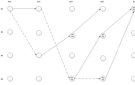
Figure (2.5.2): The trellis Diagram structures in discrete intervals
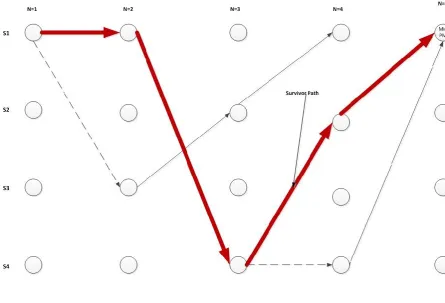
Figure (2.6.1): The survivor paths of a trellis diagram based on Viterbi Decoding
Figure (2.7.1): The BCJR algorithm parameters in the trellis
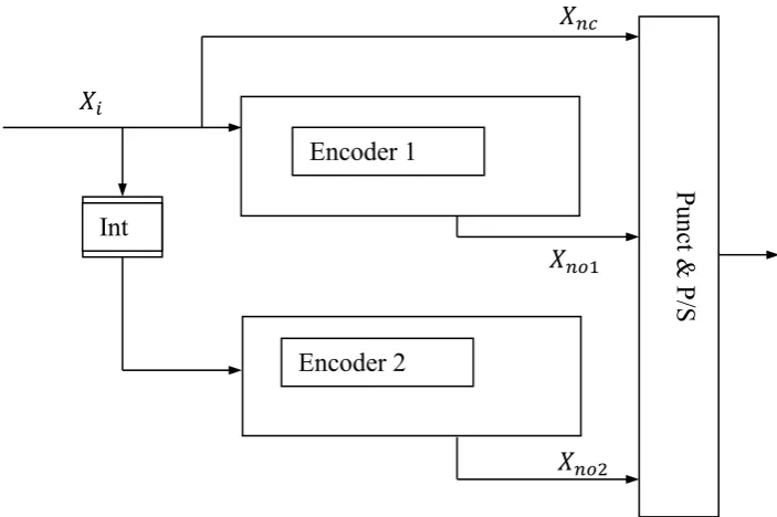
Figure (2.8.1): The encoding structure of the Turbo scheme
Figure (2.8.2): Block diagram structure of the Turbo Decoder
Figure (2.9.1): Quadrature Phase Shift Keying Mapping
Figure (2.9.2): Constellation mapping of DCM: (A1) = S [N]; (A2) = S[N+50]
Figure (2.9.3): Constellation mapping of DC 32-QAM: (B1) = S [K]; (B2) = S[K+50]
Figure (3.1): Scheme of the Design development
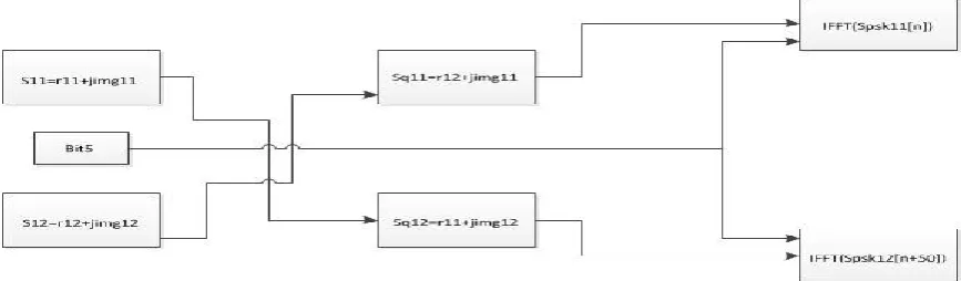
Figure (3.2): The formation of the modulation across the dual complex symbols
Figure (3.3): The two distance metrics across the 8 signal constellation points
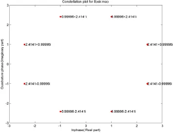
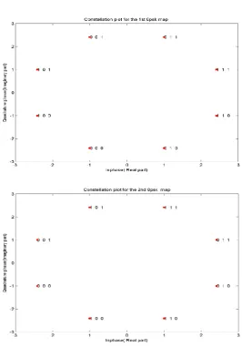
Figure (3.4): The constellation maps used for the dual 8-ary PSK symbols
Figure (3.5): The transmitting configuration design across the two antennas
Figure (3.6): The design scheme of the dual receivers
Figure (3.7): The design scheme for the modified dual receivers
ix
Figure (4.2): Time window for discretisation
Figure (4.3): Comparison between IEEE803.15.3a model and its modified version
Figure (4.4): Time and frequency channel response
Figure (4.5): The decoding regions for the MSB of the PSK symbols
Figure (4.6): Expression of the metric length position
Figure (4.7): The proposed model
Figure (5.5.1): BER Simulation of MIMO DC32QAM vs SISO DC32QAM
Figure (5.5.2): BER Simulation of MIMO DCM vs SISO DCM
Figure (5.5.3): BER Comparison between DCM, DC32QAM and MIMO model
Figure (5.5.4): Impulse response with its time response and impulse realisation
Figure (5.5.5): Comparison between analytical Rayleigh and Simulation models
Figure (5.5.6): BER results of DC32QAM, Analytical and MIMO models
Figure (5.5.7): Comparion of the models error peromances using hard decoding
Figure (5.5.8): BER comparison of the model using LLR de-mapping method
Figure (5.5.9): Comparison of BER performance between ML soft and LLR de-mapping methods
Figure (5.5.10): BER performance comparison for soft decoding at low SNR
Figure (5.5.11): SISO DC32QAM vs MIMO DC32QAM BER evaluation
Figure (5.5.12): Models comparison with impairments in the CSI
Figure (5.5.13): Spatial orthognality effect on BER of the proposed model
Figure (5.5.14): BER model performance based on rearranged constellation maps
Figure (5.5.15): Analytical upper bound error probability comparison
Figure (5.5.16): BER comparison between the proposed models
Figure (5.5.17): Performance comparison of the models over coverage area
x
List of Tables
Table (2.1): The defined data rates and modulation parameters in ECMA standard
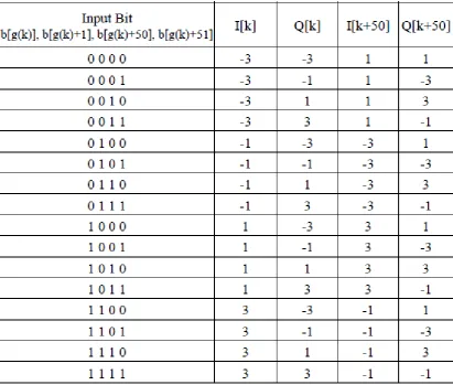
Table (2.9.2): The DCM mapping signal across the constellation maps
Table (4.1): Frequency transformation parameters
Table (4.2): Transmitting parameters
Table (4.3): Paramteters of Matlab viterbi function
xi
Abbreviations
DC 32-QAM Dual Carrier 32 Quadrature Amplitude Modulation
DCM Dual Carrier Modulation
UWB Ultra Wide Band
QPSK Quadrature Phase Shift Keying
8PSK Eight Phase Shift Keying
OFDM Orthogonal Frequency Division Multiplexing
MB-OFDM Multiband Orthogonal Frequency Division Multiplexing
CSI Channel State Information
RMS Root Mean Square
ML Maximum Likelihood
ZPS Zero-PaddedSuffix
MSB Most Significant Bit
SISO Single Input Single Output MIMO Multiple Input Multiple Output
OFDM Orthogonal Frequency Division Multiplexing
G1 Group One containing five interleaved and coded bits
G2 Group two containing 2nd five interleaved and coded bits PSK Phase Shift Keying
PLCP Physical Layer Convergence Protocol
PPDU PLCP Packet Data Unit
PSDU Physical Service Data Unit
FCC Federal Communications Commission
LLR Log Likelihood Ratio
xii
FDS Frequency Domain Spreading
TFI Time Frequency Interleaving
FFI Fix Frequency Interleaving
TFC Time Frequency Coding
FFT Fast Fourier Transform
FEC Forward Error Correction
STBC Space-Time Block Code
STTC Space-Time Trellis Codes
AWGN Additive White Gaussian Noise
IEEE Institute of Electrical and Electronics Engineers
IEEE 802.15 Working Group of IEEE
IFFT Inverse Fast Fourier Transform
BCJR Bahl Cocke Jelinek and Raviv algorithm
Log-MAP Logrithmic Maximum A Posteriori decoding
SOVA Soft Output Viterbi Algorithm
ECMA-368 ECMA international Standard for UWB technology
PER Packet Error Rate
LOS Line Of Sight propagation
BER Bit Error Rate
NLOS Non Line Of Sight propagation
SNR Signal to Noise Ratio
xiii
Abstract
The research activities over the three years were presented in this thesis. The work
centred on the use of multiple spatial elements for Ultra wide band wireless system
in order to increase the throughput, and for wireless range requirement applications,
increases the coverage area. The challenges and problems of this type of
implementation are identified and analysed when considered at the physical layer.
The study presents a model design that integrates the multiple antenna configurations
on the short range wireless communication systems. As the demand for capacity
increases in Wireless Personal Area Networks (WPAN); to address this issue, the
framework of the Wi-Media Ultra Wide Band (UWB) standard has been
implemented in many WPAN systems. However, challenging issues still remain in
terms of increasing throughput, as well as extending cellular coverage range.
Multiple Input Multiple Output (MIMO) technology is a well-established antenna
technology that can increase system capacity and extend the link coverage area for
wireless communication systems. The work started by carrying out an investigation
into integrated MIMO technology for WPANs based on the Wi-Media framework
using Multi-band Orthogonal Frequency Division Multiplexing (MB-OFDM). It
considered an extensive review of applicable research, the potential problems posed
by some approaches and some novel approaches to resolve these issues. The
proposed ECMA-368 standard was considered, and a UWB system with a multiple
antenna configuration was undertaken as a basis for the analysis. A novel scheme
incorporating Dual Circular 32 - QAM was proposed for MB-OFDM based systems
xiv
coverage area at compromise of the data rate. The scheme was incorporated into a
spatial multiplexing model with measured computational complexity and practical
design issues. This way the capacity could be increased to twice the theoretical
levels, which could pay the way to high speed multi-media wireless indoor
communication between devices. Furthermore, the range of the indoor wireless
network could be increased in practical wireless sensor networks. The inherent
presence of spatial and frequency diversity that is associated with this multiple
radiators configuration enlarge the signal space, by introducing additional degrees of
freedom that provide a linear increase in the system capacity, for the same available
spectrum. By incorporating the spatial elements with a Dual Circular modulation that
is specified within the standard, it can be shown that a substantial gain in spectral
efficiency could be possible. A performance analysis of this system and the use of
spatial multiplexing for potential data rates above Gigabit per second transmission
were considered. In this work, a model design was constructed that increases the
throughput of indoor wireless network systems with the use of dual radiating
elements at the both transmitter and receiver. A simulation model had been
developed that encapsulate the proposed design. Tests were carried out which
investigate the performance characteristics of various spatial and modulation
proposals and identifies the challenges surrounding their deployments. Results
analysis based on various simulation tests including the IEEE802.15.3a UWB
channel model had shown a lower error rate performance in the implementation of
the model. The proposed model can be integrated in commercial indoor wireless
networks and devices with relatively low implementation cost. Further, the design
used in future work to address the current challenges in this field and provides a
1
1Introduction
1.1 Overview
The Wireless Personal Area Network (WPAN) is a short range communication
system that interconnects various applications in the home and office environments.
WPAN networking technology has grown considerably in the last few years, partly
because of the advances in the underlying technology and partly due to its
commercial merits penetrating the consumer market. Nevertheless, since the Federal
Communication Commission’s (FCCs) decision to allow unlicensed UWB operation
in the 3.1-10.6GHz spectrum with power restrictions [1], there has been a surge in
the number of commercially available short range wireless portable products. There
has also been a growing interest in the technology from the academic community due
to the potential benefits of wireless short range communications. There are currently
various wireless communication networks that includes cellular, GPS, Military,
Emergency and public services all of which had been assigned to a particular part of
the frequency spectrum. The decision to allow unlicensed WPANs in the UWB
spectrum has presented at the same time an opportunity and a challenge for RF
designers. In a design approach, the flexibility over the physical layer has meant that
2
applications tailored to a specific environment. The difficulty on the other hand
stems from the spectral mask that has been defined in the proposal. This is because
the federal authority requirements concerning the radiated power have made it very
challenging to design receivers that distinguish between noise and signal data at very
low power levels. Highly sensitive receivers, by their very nature require
complicated design and hence increase the processing cost as well as the financial
cost. The IEEE have established the IEEE 802.15.3a standards group based on
previous research work by [2], in order to develop a standard model for the UWB
PAN physical layer proposal and to meet the growing demands in UWB applications
with high data rates. Although, the proposed standard has been dropped due to a
disagreement between two subgroup proposals, the model has considered
fundamental characteristics of the propagation channel which has been used in other
proposals and standards. One practical challenge has been surrounding UWB
communications for a while which is how to emulate the wireless medium. For
example, could a deterministic model based on only measured data be enough to
describe the wireless channel. The IEEE 802.15.3a standard has combined a number
of data analyses for different measurement campaigns in a stochastic model and these
were based on common propagation parameters that define many of the UWB
wireless communication systems. Another key element to consider in the design of a
channel model is the representation of multipath propagation in which the IEEE
802.15.3a standard has represented in terms of clustering using the Saleh-Valenzuela
(SV) modified model. This representation resembles the arrival of multipath
components of real measurement data of UWB waveforms. This type of observation
has helped significantly in the way modern channel models can be developed in
simulation.
3
approaches to utilising the spectrum for short range wireless data communication.
One classic approach had used all the available spectrum of the signal at very low
power with very with very short duration to transmit information, where additional
capacity could be obtained by incorporating a pseudo random spreading sequence
with the signal pulse. Such approach makes use of the spatial property of these pulses
in combating signal fading. Furthermore, there is no need for a carrier signal in this
method as it tends to consume power and spectrum both of which are very scarce.
Although this type of transmission scheme has been the traditional approach, the
single band nature of its communication has remained a point of discussion in
industry and research communities. In [3], a discussion regarding the physical layer
has highlighted the concept behind the multiband design. Here, the model has been
one which divides the large spectrum into sub-bands of 500 MHz or more and
modulating the signal information using Orthogonal Frequency Division
Multiplexing (OFDM). OFDM has been used for many years in conventional RF
communications and has proved its effectiveness. Moreover, the underlying technical
knowledge has been familiar to designers and researches alike, and hence made more
sense for the scheme to be considered in research studies. Nevertheless, there is a
major difference between OFDM in the narrowband and ultra wideband applications.
In narrowband systems, OFDM symbols are transmitted over a single band, while in
UWB domains, the symbols are interleaved over different bands. This inevitably
requires reconsideration of the physical layer protocol, and should take into account
coding and transmission design procedures.
The Multiband OFDM Alliance Special Interest Group (MBOA-SIG) of industrial
4
applications. The industrial backing of this scheme has shaped consumer electronics
in the UWB domains and has resulted in its integration on the Universal Serial Bus
(USB) and Bluetooth-SIG systems. In addition, the publication of the ECMA-368
standard [4] by the Wi-Media Alliance has forwarded the technology into the
commercial market and facilitated worldwide recognition. The ECMA-368 standard
defines the physical layer and Medium Access Control (MAC) sub layer interface for
short range wireless high speed communications. It was very important to
standardise the free license in order to push the technology developments forward.
When considering antenna technology for UWB systems a combination of frequency
division and Multiple Input Multiple Output (MIMO) antenna schemes could be used
in WPANs. The benefits of implementing MIMO technology in wireless
communications have been well proven and documented for narrow band systems.
The rapid increase in indoor multimedia networked applications from high-definition
television (HDTV) to fully integrated home and office devices that rely on short
range wireless links have highlighted the need for the multiple antenna technology in
the UWB domain. If MIMO had been incorporated in the physical layer, then the
received power could be enhanced as well as the range without violating the low
emission levels imposed by the regulation authorities. Due to the large bandwidth
available in UWB systems, frequency diversity tends to exists in such configuration
which could be used in the information coding process to increase the rate of
transmission. Although MIMO technology seems to represent an obvious solution for
increasing the capacity of UWB applications, there has been a slow progress in its
integration in commercial products. One of the key challenges for the technology has
been the increase in the complexity and cost to the front end RF modules as well as
the signal processing algorithms. On the one hand wireless portable devices for
5
complexity. On the other hand, multiple antennas need special transmission coding
and demodulation, and that increases the processing in the transmitter and receiver.
Nevertheless, the rapid demand for WPAN in the last few years has raised the
technology profile in the commercial world, and that has fostered more research in
PANs. However, and more importantly, MIMO systems and their implementation
have moved a long way in the last decade with the developments of more advanced
signal processing algorithms. These developments have in turn enabled RF
engineers to pursue very complex wireless link designs and introduce novel concepts
in the transmission layer protocols.
1.2 Research aim and Objectives
The aim of this research was to propose a multiple spatial simulation model at the
physical layer that operate in the Ultra wide band domain for Wireless personal Area
Networks to enable an increase in the transmission rate to a maximum of dual the
current available rate without an increase in the transmission power, or a reduction in
the error performance. In addition, it facilitates an improvement in the data rate for
6
increase in the wireless communication link for wireless range sensitive applications.
For these applications, it was possible to increase the transmission range at the
expense of the available data rate by a modification to the receiving algorithm. The
proposed model would have the ability to vary the information rate in the link
depending on the status of the channel. The scheme makes use of the channel
diversity to reduce the fading correlation factors and improve the error performance
of the wireless model. This research deals with the standard model that had been
implemented in real commercial and consumer electronics. Due to the strong backing
by various industrial consortia, the ECMA-368 standard had been developed and
adapted in many commercial products. Hence, the intended model considers the
ECMA-368 standard physical layer requirements and conditions in the implantation
process. In particular, a method of integrating MIMO with MB-OFDM transmission
was developed. Although developments in MIMO technology for narrow band
systems had produced a large number of research papers in the literature, the volume
of literature containing these techniques in application to UWB remain very scarce.
The area of concern governs this research manifest itself in the design and
implementation of MIMO model with orthogonal frequency division modulation that
fits within the WPAN-UWB systems. The model would be tested against an
appropriate channel model test-bed in order to validate this proposed work. Hence,
the model was evaluated using the defined standard channel model proposed by the
7
standard, as well as stochastic channel model. The standard model produced by the
IEEE was well suited to simulation and there were useful properties that would assist
in finalising the models design. Statistical models aim to analyse certain channel
parameters that describe the propagation mechanism. The use of multiple antennas in
WPANs would be evaluated and an implementation process would be developed
reflect the other area of concern. Spatial multiplexing would be explored and a novel
method that optimises the multiple antenna schemes for the system would be
developed. The MB-OFDM scheme enables symbol modulation in the frequency
domain using spectral multiplexing, and incorporating the independent fading across
different spectrum. Therefore, the spreading of the transmitted data into different
frequencies optimises the cross correlation between spectrum tone signatures leading
to improvement in the system performance, and allows efficiency in increasing the
information rate. In addition, by combining the spatial and frequency domains, the
signal space would significantly enlarge, and that would provide a foundation for
rich media content transmission eventually approaching gigabit rates. Furthermore,
an evaluation of the encoding on the signal data using spatial multiplexing as well as
spatial and frequency diversity would be carried out to maximise the transmission
range, and optimising the system capacity. This takes into account the introduction of
spatial degree of freedom in the signal space, as a result of multiple antennas
introduction in the physical space. The design would cultivate the multi-radiating
elements advantages across the multiple dimensions coding in the physical layer
protocol. The model requirements encapsulate a design that is practically feasible and
able to adapt to different system design specifications. It would contain a scalability
8
The specific objectives of the proposed model in this research were to induce an
algorithm that combines multi-antenna with multiband UWB WPAN systems. It
should produce a suitable MIMO technique for the operation in Wireless personal
area network communication systems. The new concept had to be conformed to the
ECMA-368 standard and the multiple spatial configuration should be integrated at
the physical layer of the standard. The design should facilitate a readjustment in the
model structure to enable increase in the wireless coverage area by encapsulating the
communication range requirement in wireless sensor networks. Therefore, it was a
requirement to produce a simulation model that covers the design requirements, and
enabling verification of this proposed concept. This evaluation should be carried out
9
1.3 Thesis Contributions
The contribution to knowledge from this research is anticipated to be presented at the
physical layer and focusing in two specific areas. The first is integrating MIMO
technique with DC-32QAM in WPAN. The model design would contribute to the
available capacity by increasing the theoretical throughput without increasing the
spectrum of operation for UWB-WPAN systems. The second would be facilitating
adjustment to the model in order to increase the transmission range of the
communication with the specified transmission power available for legacy wireless
system devices and single radiating element within wireless networks intended for
indoor applications. This increase in the coverage area would be specific to wireless
sensor network application where the range is more critical than the throughput.
10
1.4 MIMO Design Implementation
The naturally inherent dense environment that exists for indoor wireless
communication presents a solid platform to explore the spatial, temporal and
frequency diversities. MIMO technology has been proven to increase the system data
rate for intensive media applications, and further enhance the available
communications range. Furthermore, the technology has been used in narrow band
systems and single band transmission processes. In this research, multiple antenna
techniques will be implemented for UWB applications with a multiband OFDM
transmission scheme. Firstly, the modulation of the signal information will be
optimised to enable fast coding processes and transmission rates. The data frames
will be spread across the antenna elements and then radiated at the same time which
will increase the system efficiency considerably. This is an important contribution to
WPAN systems in which a multi-antenna algorithm has been embedded in a
multiband spectrum to enhance the overall capacity. Increasing the models capacity
will have a direct impact on all forms of short range wireless communications. For
example, a multimedia transmission between a set box and a television could be
enabled without degrading the quality or increasing the compression coding.
Alternatively, a network of several portable devices could be launched where devices
perform different operations all at the same time. It could also further extended to the
automotive industry where inboard entertainment systems could be facilitated, and
more applications and functions could be realised. The implication of MIMO
11
between peripheral devices at very high data rates.
1.5 Modelling challenges of physical channel
UWB spectrum is very board and due to that, there is a variation in the frequency
response of the system operating in these frequency bands. This challenge makes it
very hard for RF designers to develop a channel model that satisfies the whole
spectrum of the transmission link. Therefore, UWB applications have been designed
based on a predefined model that specified for that particular wireless link system
and its defined spectrum band of operation. This was then applied across the channel
domain, and therefore the modelling of the channel had combined stochastic
approach as well as actual channel measurements. Short range wireless portable
devices operating on this channel should be designed so as to operate across the
frequency bands, and should overcome the channel fading signatures differences
between high and low end of the spectrum. In order to give an accurate account for
the proposed design, the final concept in this project should deliver good
performance across different channel models. The work proposed in this research
12
identifying the multiple paths in indoor environments would have to be enhanced and
optimised. In particular how the scattering signals could be reflected in the multipath
model and the impulse response of the channel. Furthermore, how this response
could be interpreted in the receiver block and how to create a novel design that
represents this physical property. The stochastic model representation would be
reviewed in order to have a better representation of the signal delay spread, and how
the received power of these waves is disturbed. In existing literature, the statistical
analysis so far has been hampered by very narrow studies of the propagation
mechanism in ultra wideband domains.
However, this work would be widening the boundary of the study to include different
environmental scenarios. Therefore, the modelling would consider diffraction,
reflection and scattering effects in the evaluation process. In addition, it is intended
that this research will present a novel model that encapsulate different propagation
scenarios, and will bridge the physical layer design barrier that limit Ultra wide band
devices within severely and hostile indoor channel propagations. The enhancement
of the proposed concept should allow the integration of several WPAN peripheral
devices resulting in an optimisation to the technology as well as reducing design
costs. Further, it opens opportunities for future research into new applications other
than the current office and home based applications. It is common knowledge that
there are new short range wireless applications becoming available across different
technology fields, each of which has a special interest in replacing wired
communication links between devices in ever more crowded networks. Hence, the
13 wireless propagation.
1.6 Research limitations
The research into the physical layer of UWB communication systems has reached a
level of maturity over the last decade, but nevertheless, there are a number of open
research questions that needed to be addressed. The physical layer encompasses the
encoding of data, the RF modules that enable the transmission and reception of data,
and the generic generation of wireless signals. Research into the first layer of the
UWB communications link had been bounded by the limited number of available
measurements obtained from the environment. The work here takes this into account,
and will therefore attempt to analyse the available experimental data that exists for
indoor wireless links. Although the modelling and simulation proposed in this
research handles various multipath channels that reflect certain geometric
configurations in home and office environments, there are some additional
observations that needed to be addressed. Firstly, the limited research in this field
makes it very challenging to obtain a comprehensive approach to the problems at the
14
spectrum had limited the available results to specific frequencies and not across the
entire spectrum. In some commercial applications, the research into wireless links
had focused on the lower bands of the UWB spectrum, and this reflected in the
development of much specialised models. Channel propagation is a physical
phenomenon that depends on objects scattering signals in all directions and this
creates an infinite number of dimensional representations.
However, research into the electromagnetic waves propagation, and the energy
distribution of the channel paths was very difficult. Modelling of the propagation
physical phenomenon and its representation for wireless indoor and office
environment is particularly challenging. All the currently available models based on
measurements and statistical representation included a data base of different types of
building furniture and decoration material etc. However, all of these representations
are still limited and do not account for every scenario. More importantly, because of
the relatively small wavelength that characterise UWB applications, scattering from
some materials tends to create a different frequency response when interacting with
these objects. This in turn, makes it very hard to design a simulation process that
absorbs these effects, and hence limit the accuracy of the design model.
A further limitation is that the MIMO configuration we aim to adopt relates to the
physical layer transmission scheme that operates on narrow band spectrum. Due to
15
multi-antenna system proposed in this research has been designed to comply with
this particular standard. Therefore, the proposed MIMO algorithm would require
further modification and optimisation in the case of a new standard's requirement.
This is because the standard uses the MB-OFDM scheme for the transmission
process and hence all the research work has been based on this type of spectrum
segmentation.
Advanced in information theory in the last decade had introduced a very high class
performance codes in the field of forward error correction class of codes. Due to the
high data rates required by this research, and the limitation in the complexity
requirements at low power wireless personal area network systems, the available
coding methods and coding rate had to be in consistent with the standard
specification. As such, iterative decoding algorithms that required feedbacks would
not be used in this research. These types of codes that required additional cost in
transmitter and receiver structures would limit the research objectives in introducing
these types of codes. A review of the advanced available methods as the turbo
decoding would be highlighted but not taken to optimise the coding process. Forward
error correction coding would be the used as the source of coding algorithm in
conformance with the standard.
Also, the ultra-wideband system generally requires very high speed clocks, and this
requires advanced digital signal processing. This presents a very practical challenge
16
considered. Designing pulses with very short periods operating at low energy level
presents a challenging software and hardware prerequisite. In addition, the cost of
developing hardware electronics for this type of application increases rapidly. In
order to maintain higher data transmission, proper decoding of the received symbols
should be realised which in turns requires complex processing units. Accurate
synchronisation is also very important for the digital signal processing block,
however the cost factor should be considered in these applications. Furthermore,
another key challenge is the interference that is created in this type of
communications link. On the one hand, there are power constraints on the
transmitted signals that tend to adversely reflect on the signal to noise ratio. On the
other hand, the error margin increases considerably as the information rate of the
system increases. In this research, some effort will be made to address all of the
above challenges and come up with useful solutions. Although, it is intended that the
resulting outcome will accomplished these prerequisites, there are observations that
will need to be identified.
17
1.7 The proposed structure of the thesis
The contents of the proposed thesis will be divided into chapters that identify specific
topics. A summary of these chapters has been provided in the following:
Chapter two will provide a review of the past and current literature of the various
concepts that underpin WPAN. It will analyse current research work in the UWB
channels and experimental studies into specific environments. A review of previous
channel propagation models will be summarised to identify certain results that are of
key interest to this work. Published studies into the area of multiple antenna
technology will be reviewed and relevant results to this project will be highlighted.
The design methodologies behind channel modelling and multiple antenna
techniques will also been outlined in the assessment. A review of the modulation
methods would be provided along with their implementation.
18
applies multiple radiating elements in the physical layer of the ECMA standard.
MIMO scheme would be designed so as to operate on Ultra wide channel model.
Different channel models would be used to evaluate the induced concept used in this
research. Explanation of the model will be firstly discussed in detail as well as the
reasoning for the design. The background to stochastic concepts behind the model
will be discussed and a comprehensive explanation to them will be included. The
scope of the scheme will cover the coding algorithm, mathematical algorithm, and
the simulation design procedure. The multiple antenna design will have been
presented covering the transmission protocol. The integration procedure of the
multiple antennas techniques in the physical layer would be explained. This includes
specifically induced design algorithm that allow multiple radiators to be absorbed in
both the transmission and demodulation schemes. The optimisation process to the
model design which was implemented in the developed system would then present.
Additional system requirements had been discussed including optional physical layer
requirements.
Chapter four presents the implementation method of the proposed work. In this
chapter, the implementation of the design had been considered and explanation to the
concept formulation was given. This implementation was carried out in the
simulation environment based on Matlab software package. The receiver’s
implementation was followed with explanation to the integration of the proposed
model on the wireless receiving structure, and the test bed requirements for the
simulation. A proposal to optimise decode method was explained that further
19
The final chapter will provide a conclusion to the research project by highlighting the
obtained results from the system model. It will outline the contribution of this work
for the short range WPAN technology and how it can be integrated in future research.
It will also identify areas in the research which could be incorporated in future
studies in PANs. A review of the validation process for the multiple antenna system
would be discussed along with comparative tests with existing approved practical
models. A detail analysis will be discussed to project the merits of the design model.
A review of standardised models will also be carried on to identify a viable test
20
1.8 Research methodology
The purpose of this section is to outline the research methodology used in the
production of multiple antennas model for Ultra wide band system used in the
Wireless Personal Area Network systems. It describes six phases including
identification, designing model, implementation, Optimisation, testing and
verification of the proposed model that was presented in this project. The adopted
research methodology for this work had been illustrated graphically in the following
21 Phase 1: Literature Review
Phase 2: Identify and analysis the challenges in the Implementation of MIMO in UWB systems
Phase 3: Designing a prototype of a physical layer wireless communication system
Phase 4: Implementation of MIMO configuration on the model design
Phase 5: System model optimisation and improvements
Phase 6: System testing and evaluation
22
Six phases approach were identified in defining an appropriate research
program structure. These are as follows
Phase 1 (Literature Review): This phase covers previous works on the
implementation of MIMO techniques on Ultra wide band wireless systems.
The focus would be on identifying the main problems and challenges that
encapsulate the technology. Various concepts would be looked at and explored
to facilitate new design models.
Phase 2 (Identifying related problems): In this section, the emphasis would
be on identifying tangible problems in the design and implementation of
spatial elements in hostile indoor environments. Challenging channel
behaviours and problems would be induced and considered for research work.
Phase 3 (Designing a prototype of a physical layer Wireless
communication system): In this stage, a prototype design model would be
constructed to enable the linking of the various physical layer blocks of the
wireless system and producing a functional and operational design model. This
interconnection allows for observation of the blocks parameters and the system
23
Phase 4 (Implementation of MIMO configuration on the model design):
MIMO construction would take place in this section and would be integrated
in the simulation model. The algorithm for implementation would be tested to
verify the system performance. The design concept would be implemented to
infer the theoretical analysis.
Phase 5 (System model optimisation and improvements): The modelling
design would be improved and optimised. Further analysis would be carried
out to improve the performance and reduce the complexity involves.
Phase 6 (System testing and evaluation): In this step, the various scenarios
would be tested and the model would be observed to finalise the design.
Evaluation would be performed on each block within the simulation model and
all the results would be documented.
24
2 Background Research
2.1 ECMA-368 Specifications
The ECMA standard specifies OFDM modulation with multiple bands in
which the spectrum had been segmented into a collection of lower frequency
bands. It divides the unlicensed spectrum into sub-bands each of which
consists of a 528MHz bandwidth, and combines a tuple of bands in Band
Groups (BG1 – BG5) except for the last two bands [5], and figure (2.1.1) gives
a description of this spectrum division. A flexible feature of the model is the
variable transmission rate in which the standard supports data rates of 53.3, 80,
25
this model, and where every band has been allocated equal number of
subcarriers. Frequency and time spreading with forward error correction
coding techniques has been used to vary the data rates. In addition the Inverse
Fast Fourier Transform (FFT) has been implemented in the construction of the
OFDM symbol. In order to apply OFDM modulation, the targeted spectrum
had been firstly divided according to the standard specification. The
transmission across multiple bands had been implemented in Time-Frequency
Code (TFC), which makes good use of the band segmentation within the
ECMA standard. The segmentation of every band groups had been shown, and
where different modulation schemes could be applied.
Figure (2.1.1): Spectrum division into band groups: Taken from [3]
[image:39.595.148.455.558.667.2]26
defined Physical Layer Convergence Protocol (PLCP) sub-layer to interface
between this layer and the upper MAC counterpart [6]. This sub-layer
provides a method for converting PHY Service Data Unit (PSDU) into PLCP
Packet Data Unit (PPDU). The PPDU structure consists of the PLCP preamble
that includes the Channel Estimation and Packet synchronisation sequences,
the PLCP header, and the PSDU. Further error detection and correction were
added to improve the wireless communication links.
Figure (2.1.2) PPDU and PLCP structure: Taken from [4]
The process of transmission consists of collect a number of packets (or frames)
in which a predefined number of modulated OFDM symbols forming the
message packet. As it had been stated, frequency domain spreading, time
domain spreading and Forward Error Correction (FEC) are used to vary the
27
coded information is interleaved over three bands and that termed as
Time-Frequency Interleaving (TFI) [7]. The second coding is where the coded
information is interleaved over two bands, and this referred to as TF12. The
third one in which the transmission was done over signal band where the term
Fix Frequency Interleaving (FFI) was used for this type of coding. Four
time-frequency codes within the first four and six bands group make use of TFI, and
three time-frequency codes uses TFI2 and FFI coding, giving support of ten
channels in each band group. In the case of the fifth band group, two
time-frequency codes uses FFI and one uses TFI2. On the other hand in the six band
group, FFI channels and one of the TFI2 channels overlap with the channels in
the third and fourth band groups. In order to allow range regularity and radio
coexistence within the standard, a mechanism for nulling the OFDM
subcarriers in the TFC operations had been provided. Frequency Domain
Spreading (FDS), and Time Domain Spreading (TDS) were been facilitated in
order to expand the bandwidth for the modulation schemes. Further, the
various coding rates were assigned to different coding and modulations
depending on the applications. Table (2.1) gives description of the different
28
In mathematical form, the transmit signal could be describes as follows [8]
x𝑅𝐹(t) = 𝑅𝑒 {∑ 𝑥𝑛(𝑡 − 𝑛𝑇𝑆𝑌𝑀) exp(𝑗2𝜋𝑓𝑐(𝑝(𝑛))) 𝑁−1
𝑐=0
𝑡} (2.1.1)
In the above formula, 𝑥𝑛(𝑡)is the baseband signal representation for the nth
symbol of within the transmitted packet, and since these are time limited
signals, then 𝑠𝑛(𝑡)will equal to zero outside time frame (0 - 𝑇𝑆𝑌𝑀). The function 𝑝(𝑛) maps the nth symbol to the appropriate frequency band, and 𝑓𝑐 is
the centre frequency for that frequency band. The OFDM symbol length 𝑇𝑆𝑌𝑀
includes the Zero Padded Suffix (ZPS). These extra suffix sequences provide a
mechanism to mitigate the effect of multipath and a guard interval to allow
sufficient time for the transceivers to switch between centre frequencies of
bands. Figure (2.1.3) shows TFC with modulated symbols including the
29
30
2.2 MIMO System
Multiple Input Multiple Output (MIMO) techniques consist of using multiple
antennas at both ends of the communication channel to exploit spatial diversity
and add another degree of freedom to the system capacity [9], [10]. The
technique combines the temporal, spatial and frequency diversities in the
transmission scheme to increase the link throughput. MIMO enables the
transmission of data over multiple channels and hence increases the available
data rate of the system [11]. This in turn produces a linear increase in capacity
without the need for bandwidth expenditure [12]. Furthermore, it doesn't
require additional transmission power and this single factor makes it very
attractive for short range wireless communication networks [13]. This is
because of the astringent power regulation imposed by federal regulators (e.g.
the FCC in the USA).
The spectrum allocation in MIMO multiband systems has been constructed by
supplying each user a sub band (with a minimum bandwidth of 500 MHz) and
all the transmitting antennas operate in the same band for each user at that
particular time duration. The encoding process has been applied across all of
the antennas, the number of subcarriers within one symbol and the number of
OFDM symbols that forms blocks or frames for transmission. This way, each
31
spectrum at the specified antenna element during a known OFDM period of a
marked frame. Due to the encoding format, a matrix representation is used in
multi-spatial systems to simplify its mathematical representation. The
sequences allocated to each user and for each antenna were designed such that
they were orthogonal to each other or the correlation factor is zero between
them [14]. This independent property ensures the formulation of a diagonal
matrix which simplifies the detection process at the receiver side and reducing
the hardware and complexity costs. The transmitted based band signal (d)
represented by each symbol to be transmitted on antenna z has been
interpreted mathematically as follows [15].
𝑑𝑧(𝑡) = √𝐸𝐴 ∑ 𝑏𝑧(𝑠) 𝑒−𝑗2𝜋𝑠∆𝑓 𝑆−1
𝑠=0
(𝑡 − 𝑇𝐴𝑃) (2.1.2)
Where E, A , b, T and f represent the total energy, the total number of antennas,
the complex symbol, the duration of the added prefix (this could be Cyclic
prefix or Zero-padding) and the sub frequency spacing between two
subcarriers. The energy of all the transmitted signals has been normalised to
eliminate the number of radiating elements, and in addition satisfying the
spectrum mask regulations [16]. A total number of Z blocks consisting of
32
matrix B and for each radiating element a number of symbols have been
allocated. That is for the 𝑎𝑡ℎ antenna, a number of complex code weights
forms a matrix X𝑎representing the duration of the OFDM symbol for the
particular block z. Furthermore, there were A antennas forming a matrix U of
all the blocks and the complex symbols. Within the symbol duration, a total of
S subcarriers are used to modulate the symbol. The channel operates across all
the subcarriers of the symbol, all symbols within the block and across all the
antennas forming a matrix CH. For every receiving antenna, a channel vector
CH𝑖of dimension ZSA x 1 has been formed consisting of a superposition to the physical link response weights from the spatial elements [17], [18].
B = [B0 , B1 , … B(Z−1) ] (2.1.3)
𝑋𝑎𝑧 = [𝑋
𝑎𝑧 (0), 𝑋𝑎𝑧 (1) , … 𝑋𝑎𝑧 (𝑆 − 1) ] (2.1.4)
CH = [CH1 , CH2 , … CHU ] (2.1.5)
CH𝑖 = [CHi1 , CHi2 , … CHiA ] (2.1.6)
The sub channel weights of the radiating elements in CH can be represented
statistically as a random variable with a magnitude having the form of the log
normal or Nakagami distribution [19]. The convolution process between the
33
statistically distributed due to the statistical nature of the channel. The fact
that, there are multiple spatial elements, the received signal is represented in a
matrix form as follow [20], [21], [22].
Due to the effects of the channel, each receiving antenna in the MIMO
configuration would receive copies of the neighbouring antenna's signals [23].
One of these weights represents the correct signal between the pair of
transmitter and receiver and the rest could be considered to be interference
[24], and for analytical purposes all the channel weights could be represented
by a vector G (of dimension AS x 1). In addition, the multipath effect produces
multiple copies for each transmitted signal and hence every channel G𝑖is expanded by a number of multipath components of length Q [25]. Additional
assumptions have been applied by [26] to simplify the computation and state
that all the radiating elements have the same number of multipath signals.
G = [G1 , G2 , … GA ] (2.1.8)
34
In the frequency domain, the channel could be decomposed into its Fourier
coefficients consisting of the subcarrier weights and the multipath components
forming a matrix F of dimension S x Q. The received signal at the ith antenna
would form a vector Y constructed from the channel Fourier matrix F and the
transmitted signal vector X [27], [28]. The power spectral density of the
received signal would form a Hermitian matrix H which could be decomposed
to its unitary and diagonal matrices using the single value decomposition.
F = [Fs0q0 , Fs0q1… Fs0(q−1) ; Fs1q0, … Fs1(q−1), … F(s−1)(q−1) ] (2.1.10)
G = F. G , Y𝑖 = (F. G). X
H = E[Y𝑖 . (Y𝑖)𝑡 ] = V A V𝑡, A = diag [a1…. a𝑘]
The eigenvalues of the received signal power is represented by the diagonal
matrix A and is used to provide a measure of the signal power at the receiver.
This power measure is then used to evaluate the system performance in terms
of the signal to noise power ratio, and as a further analysis tool to measure the
coverage area. The addition of the noise to the received signal power would
increase the amount of distortion in the received OFDM symbols, and hence
affecting the bit error rate of the system. Additive White Gaussian Noise
(AWGN) has been used in the modelling and design simulation in previous
research work [29], [30], [31]. The inherent rich diversity that encapsulates
indoor wireless communication [32], and the frequency selectivity property of
35
assumptions [33]. These have assumed that the spectrum of each sub band that
the symbol hops across was independent of each other and were not correlated.
Implementing this assumption for the evaluation of the MIMO model
performance, has shown that using the multiband approach with symbol
hopping increases the system performance and provides an additional degree
of freedom in the frequency domain. Nevertheless, further research is needed
to be carried out concerning the operation of multiband transmission plans in
the UWB systems. This includes determining more accurate statistical models
for the MIMO capacity in the physical medium, and the spectrum power for
each of the sub bands across each band group.
2.2.1Alamouti Scheme Space-Time Block Code (STBC)
The growing demand for more channel capacity had led to research in the
spatial domain to add an extra degree of freedom to the capacity. The break
through that was captured by Alamouti scheme [34], which had opened a new
36
The scheme uses two transmit antennas, two time intervals, and a novel
complex orthogonal principle that uses space-time technique to increase the
performance without increasing the signal power. A code-word matrix was
formed from two consecutive symbols (s1,s2), and their complex conjugate
counterparts in a dual time pins as follows
𝑿 = [𝑠1 −𝑠2∗
𝑠2 𝑠1∗ ] (2.2.1)
The scheme using two symbol periods to transmit the dual symbols from two
antennas, and therefore in essence the original content information would be
transmitted twice across the time intervals. The original principle was
formation of the matrix𝑿, which is a complex orthogonal matrix as
𝑿 𝑿𝐻= [|𝑠1|2+ |𝑠2|2 0
0 |𝑠1|2+ |𝑠2|2]
= |𝑠1|2+ |𝑠2|2∗ 𝑰
2 (2.2.2)
This orthognality of the matrix of rank two gives the Alamouti code a diversity
gain of 2. The diversity analysis was based on the Maximum likelihood
detection. Nevertheless, there is a critical condition that fading should remain
invariant of the two consecutive symbol periods for every spatial code.
[𝑦𝑦1
2∗] = [
ℎ1 ℎ2
ℎ2∗ −ℎ 1∗] [
𝑥1 𝑥2] + [
𝑛1
37
At the receiver, estimating the channel coefficients will lead to multiplying the
received noisy signal vector with the channel matrix will lead to the following
[ℎℎ1∗ ℎ2
2 ∗ −ℎ
1] [
𝑦1
𝑦2∗] = [ℎ1 ∗ ℎ
2
ℎ2∗ −ℎ 1] [
ℎ1 ℎ2
ℎ2∗ −ℎ 1∗] [
𝑥1
𝑥2] + [
ℎ1∗ ℎ 2
ℎ2∗ −ℎ 1] [
𝑛1 𝑛2∗]
[𝑦̂𝑦̂1
2∗] = [|ℎ1| 2+ |ℎ
2|2] [
𝑥1 𝑥2] + [
ℎ1∗𝑛
1 + ℎ2𝑛2∗
ℎ2∗𝑛
1+ ℎ1𝑛2∗ ] (2.2.4)
Due to the orthognality of Alamouti code, simple ML receiver would estimate
the transmitted symbol as follows
𝑥̂𝑗 = 𝐸𝑟𝑟𝑜𝑟 𝑓𝑢𝑛𝑐𝑡𝑖𝑜𝑛 (|ℎ 𝑦̂𝑗
1|2+|ℎ2|2) = 𝑄 (
𝑦̂𝑗
|ℎ1|2+|ℎ2|2) (2.2.5)
It is important to note that, the two main objectives in using orthogonal
space-time code were to increase the diversity order, and reducing the complexity of
symbols detection at the receivers. Further, the complex orthogonal codes
would not exists for a number of spatial elements that is greater than two with
the defined objective goals mentioned before. STBC could be further
improved in terms of its coding gain by using convolutional encoders as in
38
2.3 The Physical Channel
There has been a significant amount of research concerning the channel
measurements for Ultra-wide band applications stemming from the practical
and theoretical difficulties these systems present. The measurement approach
has been carried out based on two distinctive domains, the time domain
approach which evaluates and measures the impulse response of the medium;
whereas the frequency domain methods deals with the channel transfer
function based on spectrum evaluation. In the time domain, channel sounders
have been implemented by using either short or high energy pulses, or more
robust methods using correlative channel sounders [35]. The latter uses wide
band signal with low Signal to Noise Ratio (SNR) to avoid interfering with the
surrounding wireless systems (e.g. narrowband applications). At the other end,
a PN sequence is used in the correlation process where the original transmitted
signal is then induced. In order to extract the channel parameters, different
measurement procedures have been performed. Two high resolution algorithm
methods that have been used in practice and have been highlighted in research
papers [36]. The first is the CLEAN algorithm which is based on an iteration
process. Received pulses are first correlated with a known pulse shape in order
to extract the strongest pulse and then iteratively extract the following
39
SAGE algorithm [37] is the other method which uses a maximum likelihood
estimate using the parameters applied with iteration process. The Vector
Network Analyser (VNA) technique is a widely used measurement method in
the frequency domain [38]. It uses a frequency sweep of sinusoidal waveform
to excite the channel and then measure its transfer function. The inherent
averaging makes it less affected by noise and interference and can perform
large band width measurements. However, due to the slow operation of
frequency stepping, this process can take a long time for dynamic channels.
Furthermore, the wiring issues tend to limit the measurements to short area
ranges. Scalar Network Analyser is a modified method that measures only the
magnitude of the transfer function and hence reduces the operation time that
VNA takes.
Measured data has shown that for the indoor channel, the scattered objects
tend to be distributed in the form of clusters between the transmitters and
receivers [39]. Furthermore, within each cluster the arrival ray tends to be
non-uniformly distributed. One important implication of the clustering assumption
is the Saleh-Valenzuela (SV) model in which multipath components follow a
Poisson distribution with inter arrival times that is exponentially distributed
[40]. Moreover, the model has a cluster and ray arrival times as well as a decay
factor value for each of them and hence provides a great flexibility in
modelling different scenarios.
40
models each of which covers certain applications under common specifications
of its physical layer proposal. These models have been developed based on
measured data and the simulation of identifiable prerequisite requirements for
system design. These were common primary characteristics of the multipath
channel such as the power delay profile, RMS delay and the number of
multipath components, and data that requires an agreement between the
measured data and the standardised models realisations.
In this section, two models that frequently mentioned in research papers are
highlighted (namely the IEEE 802.15.3.a and IEEE 802.15.4a).
For office and residential indoor environments, the IEEE 802.15.3a task group
have been established with communication ranges of less than 10 m [41]. The
model parameters were based on measurements and define four separate radio
environments with different ranges ( LOS 0-4m CM1, NLOS 0-4m CM2,
NLOS 4-10m CM3, MPCs CM4). The IEEE 802.15.3a standard is based on
the SV model with large and small scale fading being modelled as lognormal
distribution with similar standard deviation values. The channel impulse
response of the standard had been modelled as follows:
ℎ(𝑡) = 𝑋 ∑ ∑ 𝐵𝑐, 𝑦 𝑒𝑗𝜃𝑐,𝑦 𝛿(𝑡 − 𝑇
𝑐 − 𝜏𝑐,𝑦 ) 𝑦
𝑐
(2.3.1)
41
Inside this model, there are three random variables with three distributions
representing the amplitude, the phase, and the time (arrival time). The first
random variable is the amplitude and represented by Rayleigh Distribution in
the original SV model. The coefficients in the path represent the amplitude (
gain = ampl of I + Q components) and were modelled as Log-normal
distribution instead of the above Rayleigh distribution [42].
f
c
, y
(
Β
c
, y
)=(
2Β
c
, y
/ ̄
Β
c
2
, y
)
e
−
Β
c, y
/ ̄
Β
c2,y
(2.3.2)
Where Β̄c 2
, y is the average power (variance)
̄
Βc2, y is the average power that is statistically distributed and every arrival
pulse will have its own power. The distribution here is the Exponential
distribution and could represent two average power values. The first one is the
average power of each ray (y) within the cluster, and the second is the average
power of each cluster (c) (Each cluster is compared in terms of its power in
comparison with other clusters i.e. The first 2 or 3 clusters normally will have
more power than the later ones). The second random variable is the phase
(Theta) which is assumed to follow Uniform distribution between [0, 2π]. The
third random variable represents time, and here there are two time of arrivals,
one for the cluster arrival time and the other for the ray arrival time within a
cluster, both of which follow a Poisson distribution [43].
𝑓𝑇𝑚(𝑇𝑚|𝑇𝑚−1) = Λ exp{−Λ (𝑇𝑚− 𝑇𝑚−1)} , 𝑚 > 0 (2.3.3)
![Figure (2.1.1): Spectrum division into band groups: Taken from [3]](https://thumb-us.123doks.com/thumbv2/123dok_us/8708454.881314/39.595.148.455.558.667/figure-spectrum-division-band-groups-taken.webp)
![Figure (2.9.2): Constellation mapping of DCM: (A1) = S [N]; (A2) = S[N+50]](https://thumb-us.123doks.com/thumbv2/123dok_us/8708454.881314/78.595.176.566.174.481/figure-constellation-mapping-dcm-a-s-n-a.webp)