International Journal of Emerging Technology and Advanced Engineering
Website: www.ijetae.com (ISSN 2250-2459,ISO 9001:2008 Certified Journal, Volume 4, Issue 12, December 2014)
208
Design and Structural Analysis of the Ribs and Spars of Swept
Back Wing
Mohamed Hamdan A
1, Nithiyakalyani S
2 1,2Assistant Professor, Aeronautical Engineering & Srinivasan Engineering College, Perambalur, India
Abstract— The aim of this paper work is to design and analyse the ribs and spars of a 150 seater regional aircraft for the stresses and displacements due to the applied loads. For this we did a comparative study on particular 150 seater regional aircraft. The optimum design parameters are suitably selected and then the model was designed using the CATIA software. The airfoil coordinates for the model to be designed, were generated by design foil software. The major wing design parameters were explained in detail and the wing configuration has been described. Different types of loads acting on the aircraft and the wing are determined and the moments, displacements, etc., are also determined. The wing structure was also explained and functions of each component and their arrangement are also studied. The methodology of finite element method and the detailed description about various FEM tools have been studied and implemented in this work.
I. INTRODUCTION
A. Aim
To find the capability of aircraft wing structure to withstand bending moment and to pressure loading.
B. Definition of Wing
The wing is a framework made up of spars and ribs and covered with metal. Wing structures carry some of the heavier loads found in the aircraft structure. The particular design of a wing depends on many factors, such as the size, weight, speed, rate of climb, and use of the aircraft. Wing is mainly used as a lift producing component in an aircraft.
C. Wing Support
Based on the support provided in the wing to the fuselage, the wing can be classified into the following types
Cantilevered
All the structure is buried under the aerodynamic skin, giving a clean appearance with low drag.
Braced
The wings are supported by external structural members
Strut braced
Wire braced
D. Aspect Ratio
The aspect ratio is the span divided by the mean or average chord. It is a measure of how long and slender the wing appears when seen from above or below.
E. Wing Sweep
Swept back- From the root, the wing angles backwards
[image:1.612.379.509.355.474.2]towards the tip. At transonic speeds swept wings have lower drag, but can handle badly in or near a stall and require high stiffness to avoid aero-elasticity at high speeds.
Figure I Swept Back Wing
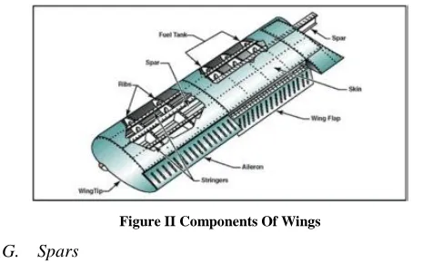
F. Components of Wing
The internal wing structure, consisting of spars, ribs and stringers, and the external wing, which is the skin
Figure II Components Of Wings
G. Spars
[image:1.612.323.555.520.665.2]International Journal of Emerging Technology and Advanced Engineering
Website: www.ijetae.com (ISSN 2250-2459,ISO 9001:2008 Certified Journal, Volume 4, Issue 12, December 2014)
209
Other structural and forming members such as ribs may be attached to the spar or spars, with stressed skin construction also sharing the loads where it is used.
Some of the Forces Acting On a Wing Spar Are
Upward bending loads resulting from the wing lift force that supports the fuselage in flight. These forces are often offset by carrying fuel in the wings or employing wing-tip –mounted fuel tanks.
Downward bending loads whilst stationary on the ground due to the weight of the structure, fuel carried in the wings, and wing-mounted engines if used. Drag loads dependent on airspeed and inertia. Rolling inertia loads.
Chord wise twisting loads due to aerodynamic effects
at high airspeeds often associated with washout, and the use of ailerons resulting in control reversal
Advantages of the Spars
The spars are the most heavily loaded parts of an aircraft. They carry much more force at its root, than at the tip.
Spars are used to carry Shear forces and Bending Moments of the wing.
H. Ribs
Ribs give the shape to the wing section, support the skin (prevent buckling) and act to prevent the fuel surging around as the aircraft maneuvers. They serve as attachment points for the control surfaces, flaps, under carriage and engines. The ribs need to support the wing-panels, achieve the desired aerodynamic shape and keep it, provide points for conducting large forces, add strength, prevent buckling, and separate the individual fuel tanks within the wing. Milled ribs are solid structures, manufactured by milling away excess material from the solid block of metal, and are also used where very high loads apply.
Load Acts on Ribs
They transmit the air load from the wing covering to the spars; Ribs extend from the leading edge to the trailing edge of the wing.
Advantages of Ribs
1. Ribs give the shape to the wing section.
2. They serve as attachment points for the control surfaces, flaps, under carriage and engines.
3. The ribs need to support the wing-panels and to achieve the desired aerodynamic shape.
4. It is used to provide Strength and prevent Buckling.
II. AEROFOIL SELECTION
A. Symmetrical Airfoils
Symmetrical airfoils have identical upper and lower surfaces. They are suited to rotary-wing applications because they have almost no center of pressure travel. Travel remains relatively constant under varying angles of attack, affording the best lift drag ratios for the full range of velocities from rotor blade root to tip. However, the
symmetrical airfoil produces less lift than a
nonsymmetrical airfoil and also has relatively undesirable stall characteristics.
Advantage of a Symmetrical Airfoil
The fact that it can produce an equal amount of lift in either direction at the same positive or negative angle of attack.
Negative lift can also be obtained with a cambered airfoil but at a very great negative angle. (this means you can fly a cambered airfoil inverted)
The inverted angle must be great enough, though, that
the effective lower area of the airfoils (which is now, in reality, the upper).
B. Cambered Airfoils
Nonsymmetrical (cambered) airfoils may have a wide variety of upper and lower surface designs. The advantages of the nonsymmetrical airfoil are increased lift-drag ratios and more desirable stall characteristics. Non-symmetrical airfoils were not used in earlier helicopters because the center of pressure location moved too much when angle of attack was changed. Cambered airfoils (asymmetric) are the kind which can generate a lift at a zero angle of attack.
C. Definition Of Airfoil
International Journal of Emerging Technology and Advanced Engineering
Website: www.ijetae.com (ISSN 2250-2459,ISO 9001:2008 Certified Journal, Volume 4, Issue 12, December 2014)
210
[image:3.612.50.282.157.408.2]D. Airfoil Nomenclature
Figure III Airfoil Nomenclature
E. Description Of Naca -9618
Figure IV Description Of Naca -9618
III. FINAL DESIGN
Figure V Wing Model
IV. STRESS ANALYSIS AND RESULTS
A. First Iteration
[image:3.612.317.569.205.514.2]Wing with three spars
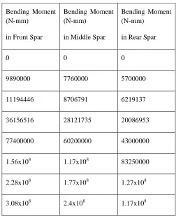
TABLE I
BENDING MOMENT FOR THREE SPARS IN ITERATION 1
Bending Moment (N-mm)
in Front Spar
Bending Moment (N-mm)
in Middle Spar
Bending Moment (N-mm)
in Rear Spar
0 0 0
9890000 7760000 5700000
11194446 8706791 6219137
36156516 28121735 20086953
77400000 60200000 43000000
1.56x10⁸ 1.17x10⁸ 83250000
2.28x10⁸ 1.77x10⁸ 1.27x10⁸
International Journal of Emerging Technology and Advanced Engineering
Website: www.ijetae.com (ISSN 2250-2459,ISO 9001:2008 Certified Journal, Volume 4, Issue 12, December 2014)
[image:4.612.53.321.130.616.2]211 TABLE II
THICKNESS FOR RIB AND SPAR WEB IN ITERATION 1
Spars Webs
I Section 20
II section 19
III section 18
IV section 17
V section 16
VI section 15
VII section 14
Ribs
I rib 2.5
II rib 2.3
III rib 2.1
IV rib 1.9
V rib 1.7
VI rib 1.5
VII rib 1.3
VIII rib 1.1
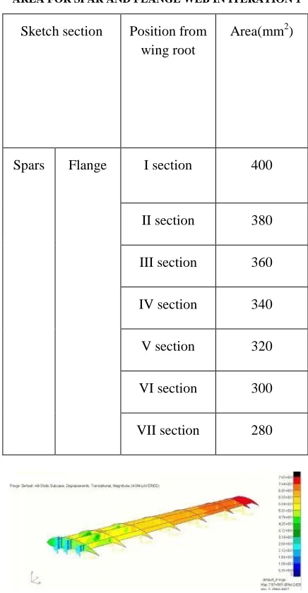
TABLE III
AREA FOR SPAR AND FLANGE WEB IN ITERATION 1
Sketch section Position from
wing root
Area(mm2)
Spars Flange I section 400
II section 380
III section 360
IV section 340
V section 320
VI section 300
VII section 280
[image:4.612.334.552.150.570.2]International Journal of Emerging Technology and Advanced Engineering
Website: www.ijetae.com (ISSN 2250-2459,ISO 9001:2008 Certified Journal, Volume 4, Issue 12, December 2014)
212 Figure VII Stress Analysis Of The Wing In Iteration 1
Here displacement is 79.7mm and stress value is coming up to 1220N/mm2.
It’s very high.
B. Final Iteration: (Iterations were made by
Changing the Thickness of the Ribs)
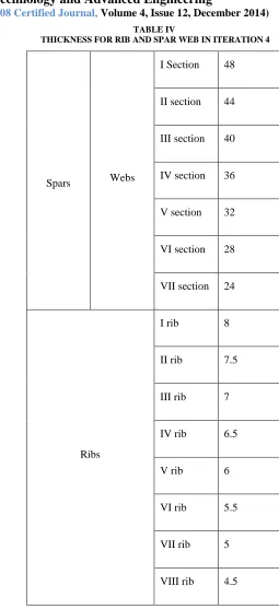
[image:5.612.54.569.81.690.2]Figure VIII Displacement Analysis Of The Wing In Iteration 4
[image:5.612.303.558.113.670.2]Figure IX Stress Analysis Of The Wing In Iteration 4
TABLE IV
THICKNESS FOR RIB AND SPAR WEB IN ITERATION 4
Spars Webs
I Section 48
II section 44
III section 40
IV section 36
V section 32
VI section 28
VII section 24
Ribs
I rib 8
II rib 7.5
III rib 7
IV rib 6.5
V rib 6
VI rib 5.5
VII rib 5
International Journal of Emerging Technology and Advanced Engineering
Website: www.ijetae.com (ISSN 2250-2459,ISO 9001:2008 Certified Journal, Volume 4, Issue 12, December 2014)
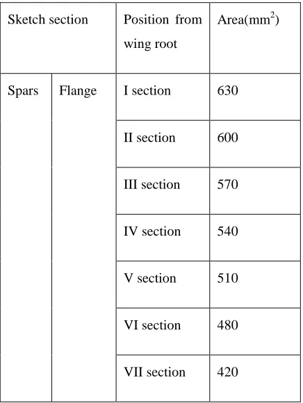
[image:6.612.60.278.158.448.2]213 TABLE V
AREA FOR SPAR AND FLANGE WEB IN ITERATION 4
Sketch section Position from
wing root
Area(mm2)
Spars Flange I section 630
II section 600
III section 570
IV section 540
V section 510
VI section 480
VII section 420
Here displacement is 52 mm and stress value is coming up to 487 N/mm2. Here the stress value is lying within the yield point of Aluminium.
V. CONCLUSION
The Yield Stress value of Aluminium is 200 N/mm2 to 600 N/mm2. The Final result shows that the required stress value of 487 N/mm2. Therefore our swept back wing can withstand the given loading condition.
For a typical 150 seater regional aircraft we have analyzed the swept back wing components by FEM, stresses are within the allowable limits. Introducing the 3 spars with the designed thickness in our swept back increases the strength. Hence the design of our wing is safe and it is not easily buckle.
REFERENCES
[1] David F. Anderson and Scott Eberhardt (2008) ‘Understanding Flight’, University of Washington, United States of America [2] Sridhar Chintapalli (2007) ‘PRELIMINARY STRUCTURAL
DESIGN OPTIMIZATION OF AN AIRCRAFT WING’, Concordia University, Canada
[3] Michael Trauttmansdorff (2005) ‘A FRAMEWORK FOR AUTOMATED SYNTHESIS AND PERTURBATION OF AIRCRAFT WING STRUCTURAL MESHES’, University of Toronto, Canada
[4] Muhammad Sohaib, (2001) ‘PARAMETERIZED AUTOMATED GENERIC MODEL FOR AIRCRAFT WING STRUCTURAL DESIGN AND MESH GENERATION FOR FINITE ELEMENT ANALYSIS’, Linköpings University, Sweden
[5] T.H.G. Megson (2003) ‘Aircraft Structures for Engineering Students’.
[6] Michael Chun-Yung Niu (1998) ‘Airframe Structural Design’, Lockheed Aeronautical Systems Company, California
[7] H. Eschenauer, N. Olhoff and W. Schnell (1997), ‘Applied Structural Mechanics’, University of Siegen, Germany