International Journal of Emerging Technology and Advanced Engineering
Website: www.ijetae.com (ISSN 2250-2459, ISO 9001:2008 Certified Journal, Volume 7, Issue 6, June 2017)
148
Speed Control of Three Phase Induction Motor Using Fuzzy
Logic Techniques
Divya Rai
1, Prof. S. R. Nigam
2Ph.D. scholar, Professor,Department of Electrical and Electronics Engineering, Aisect University, Bhopal., India
Abstract— Induction motor is widely used in industries because of its high robustness, reliability, lower cost, high efficiency, self starting capability and simplicity. Most of the applications require fast and smart system for control of speed. The speed control of induction motor is important to achieve maximum torque and high efficiency. In many motor control applications use of fuzzy logic (Soft computing technique) is gaining interest due to its non- linearity handling features and independence of the plant modeling. The fuzzy logic controller relies on a set of simple linguistic if-then rules based on expert’s knowledge. This paper presents a rule-based Mamdani type FLC applied to scalar closed loop volt/Hz induction motor control with slip regulation and its simulation results. Various toolboxes in Matlab are used for testing the simulated design.
Keywords— Induction motor, Fuzzy logic controller, Matlab, scalar, Mamdani.
I. INTRODUCTION
Induction Motors are used nowadays in wide range of applications requiring variable speed. Variable speed drives for Induction Motor (IM) require both wide range of operating speed and faster torque response, regardless of load variations. Thus more advanced control methods are needed to meet the real demand.
The conventional control methods have the following drawbacks-
1. It is dependent on the accuracy of the complex mathematical model of the system.
2. The expected performance is not reached due to the load disturbances, motor saturation and thermal variations. 3. Classical linear control shows good performance only at one speed of operation [9].
To avoid the inherent undesirable characteristics of conventional control approaches, Fuzzy Logic Controller (FLC) has been developed. FLC is based on linguistic approach to develop control algorithms for any system. It maps the input-output relationship based on expert’s knowledge and hence, does not depend on an accurate mathematical model of the system .This makes the FLC having tolerance to variations in parameters and more accurate and reliable [4-6].
II. INDUCTION MOTOR DYNAMIC MODEL
The dynamic modeling of the induction motor is done in Simulink/Matlab by using its mathematical equations which are given below. Synchronous frame of reference is used where-
w0 = base frequency
wm = rotor frame frequency
wk = dq frame frequency
ws = synchronous frame frequency;
(rad/sec)
λs = stator flux λr = rotor flux
Rs, Rr =stator and rotor resistance
vs , vr = stator and rotor voltage
is , ir = stator and rotor current
Ls , Lr = stator and rotor inductance
Lm = magnetizing inductance
Lsl = stator leakage inductance
Lrl = rotor leakage inductance
Te = electromagnetic torque
TL = load torque
Bm = viscous friction coefficient;
(pu)
d,q = direct, quadrature axis
p = number of poles
H = inertia constant(s)
International Journal of Emerging Technology and Advanced Engineering
Website: www.ijetae.com (ISSN 2250-2459, ISO 9001:2008 Certified Journal, Volume 7, Issue 6, June 2017)
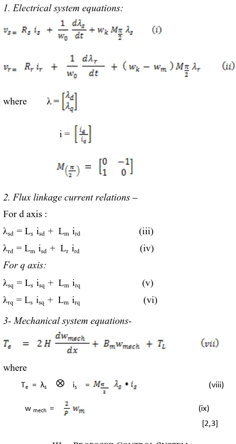
149 1. Electrical system equations:
where λ =
i =
2. Flux linkage current relations –
For d axis :
λsd = Ls isd + Lm ird (iii) λrd = Lm isd + Lr ird (iv)
For q axis:
λsq = Ls isq + Lm irq (v) λrq = Ls isq + Lm irq (vi)
3- Mechanical system equations-
where
Te = λs is = (viii)
w mech = (ix)
[2,3]
III. PROPOSED CONTROL SYSTEM
The open-loop control of induction motor has poor dynamic performance therefore various control techniques have been used in many applications to get high dynamic performance, tracking speed, and generate maximum torque of induction motor, namely scalar control and field oriented control [5].
Scalar Control
[image:2.612.45.287.132.587.2]Scalar control implies change in magnitude of the control variables only, and disregards the coupling effect in the machine. Scalar control has been widely used in industry because its implementation is easy. The scalar control strategy is simplified volts/Hertz control scheme based on stator frequency regulation as shown in fig.1. As the controller generates the slip speed ωsl signal that is added with electrical speed which gives synchronous speed ωs that is used in induction motor model having synchronous reference frame generating the voltage command through Volts/Hz function to keep flux constant [10,11].
Fig 1. Block diagram of Scalar Control of Induction Motor.
Fuzzy Logic Controller
FLC is a technique to create human-like thinking into a control system. FLC can be designed to apply human deductive thinking, that is, the process people use to reach conclusions from what they know. FLC has been primarily applied to the control of processes through fuzzy linguistic descriptions [6, 9].
International Journal of Emerging Technology and Advanced Engineering
Website: www.ijetae.com (ISSN 2250-2459, ISO 9001:2008 Certified Journal, Volume 7, Issue 6, June 2017)
150 The structure of FLC is shown in fig.2. The structure shows four functions,each one materialized by block [1,13].
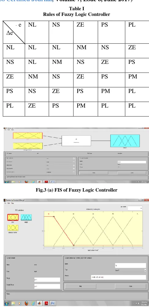
[image:3.612.319.562.125.625.2]• A fuzzifier, initially converts the crisp error and its rate of change in displacement into fuzzy variables; then they are mapped into linguistic labels. Membership functions are defined within the normalized range (-1, 1), and associated with each label: NL (Negative Large), NS (Negative Small), ZE (Zero), PS (Positive Small), PL (Positive Large). Five MFs are chosen for e ( pu) and ce (pu) signals and seven for output. All the MFs are symmetrical for positive and negative values of the variables. Thus, maximum 5х5 = 25 rules can be formed as tabulated in table 1.
Fig 2. Structure of Fuzzy Control.
• A knowledge base (a set of If-Then rules), which contains the definition of the fuzzy subsets, their membership functions, their universe discourse and the whole of the rules of inference to achieve good control. • An inference mechanism (or fuzzy inference), which is
heart of a fuzzy control, possess the capacity of taking the human decisions and the expert’s decision making in interpreting and applying knowledge to control the plant at its best.
• A defuzzifier, which converts the conclusions of the inference mechanism into actual inputs for the process.
The gains G1, G2, and G3 are scaling factors to adapt the variables to the normalized scale. However, the inference strategy is the Mamdani algorithm [5].
Table I
Rules of Fuzzy Logic Controller
e Δe
NL NS ZE PS PL
NL NL NL NM NS ZE
NS NL NM NS ZE PS
ZE NM NS ZE PS PM
PS NS ZE PS PM PL
PL ZE PS PM PL PL
Fig.3 (a) FIS of Fuzzy Logic Controller
[image:3.612.80.257.317.368.2]International Journal of Emerging Technology and Advanced Engineering
Website: www.ijetae.com (ISSN 2250-2459, ISO 9001:2008 Certified Journal, Volume 7, Issue 6, June 2017)
151 Fig.3 (c) Membership functions of output- control of slip
Fig.3 (d) Rules of FLC
Fig.3 (e) Rule View of FLC
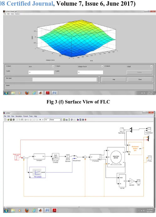
Fig 3 (f) Surface View of FLC
Fig 4. Scalar Control Of Induction Motor In MATLAB/SIMULINK
IV. SIMULATION RESULTS
[image:4.612.319.568.118.464.2] [image:4.612.49.291.122.284.2] [image:4.612.47.289.297.612.2]International Journal of Emerging Technology and Advanced Engineering
Website: www.ijetae.com (ISSN 2250-2459, ISO 9001:2008 Certified Journal, Volume 7, Issue 6, June 2017)
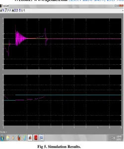
[image:5.612.49.299.125.424.2]152 Fig 5. Simulation Results.
V. CONCLUSIONS
Fuzzy logic controller shows faster response with induction motor. This controller gives maximum torque over the entire range of speed .Simple linguistic if-then rules control the speed. This speed controller based on fuzzy logic technique shows fast response and smooth performance.
REFERENCES
[1] A. Mechernene, M. Zerikat and M. Hachblef, 2008 , “Fuzzy speed regulation for induction motor associated with field-oriented control”, IJ-STA, volume 2, pp. 804-817.
[2] Divya Asija, 2010 “ Speed Control of Induction Motor using Fuzzy-PI Controller”, IEEE, 2nd International Conference on Mechanical and Electronics Engineering(ICMEE2010), vol.2, pp.460-463. [3] Ramon C.Oros, Guillermo O.Fortr, Luis Canali, “Scalar Speed
Control of a dq Induction Motor model using Fuzzy Logic Controller” .
[4] S. Beierke, C. von Altrock, 1996, “Fuzzy logic enhanced control of an induction motor with DSP”, 5th IEEE International. Conf. on Fuzzy Systems, New Orleans, LA.
[5] Basem M. Badr,Ali M.Eltamaly and A.I.Alolah, “Fuzzy Controller for Three Phase Induction Motor Drives”.
[6] Ali Zilouchian, Mo Jamshidi, 2001, “Intelligent Control Systems Using Soft Computing Methodologies”, CRC Press LLC.
[7] P. C. Sen, 1996, Principles of Electric Machines and power electronics, Wily, 2nd edition.
[8] Dr. Shailendra Jain, 2011, Modeling & Simulation using Matlab® -Simulink®, First Edition.
[9] V. Chitra, and R. S. Prabhakar, 2006, “Induction Motor Speed Control using Fuzzy Logic Controller”, World Academy of Science, Engineering and Technology.
[10] B. K. Bose,2002, Modern Power Electronics and AC Drives, Prentice-Hall, Upper Saddle River, NJ.
[11] F. Betin, D. Depermet, P. Floczek, A. Faqir, V. Lanfranchi, D. Pinchon, C. Goeldel, A. Capolino, 2001, “ Fuzzy Logic Scalar Control For Induction Machine Drive : Comparison With Classical Drive” International AEGEAN Conference on Electrical Machines and Power Electronics.
[12] Y. Miloud, A. Draou, 2001, “Fuzzy Logic Speed Control of an Indirect Field-Oriented Induction Machine Drive”, Conf. Rec. IEEE/IECON’01 Denver, USA, pp. 2111-2116.