2018 3rd International Conference on Information Technology and Industrial Automation (ICITIA 2018)
ISBN: 978-1-60595-607-7
Research and Implementation of Tunnel
Lighting Intelligent Control System
Based on ZIGBEE Wireless Technology
Huamei Zhou, Zhiqiang Meng, Duanfeng Li and Huaan Zhou
ABSTRACT
Aiming at the complicated wiring and serious energy waste of common tunnel lighting, an intelligent lighting control system is elaborated. Main controller of the system uses a fuzzy algorithm to calculate the required value of brightness. The system adopts ZIGBEE wireless network technology to realize the function of intelligent dimming, switching lamp and automatically detecting and positioning lamp fault. To meet energy-saving and intelligence, the overall design plan from the main controller to the coordinator and then to the wireless node (including router and terminal controller) is expounded. The wireless network technology and the designs of hardware and software for coordinator and wireless node are described, and the communication protocol between the coordinator and the main controller was designed. The actual operation results of the 5 tunnels in Hunan indicate that the system can meet the requirements of tunnel lighting and ensure the safety of traffic. Compared with traditional tunnel lighting, the system can save 55% energy.1
INTRODUCTION
With the rapid development of the national economy, Chinese road construction is expanding, and china has become the country with the fastest road development and the largest number of tunnels in the world. In the tunnel electromechanical system, the lighting load accounts for about 30 percent of the total electricity consumption, there is a large space for energy-saving renovation [1-2]. However, the
1
Huamei Zhou, Zhiqiang Meng, College of Electrical and Information Engineering, Hunan University, Chang Sha, China
Duanfeng Li, Hunan PEAK Traffic Engineering Company, Chang Sha, China
current tunnel lighting control system normally adopts wired dimming control or sub-loop control. The wired dimming construction has high cost, complicated wiring, and complicated on-site construction process, which increases the risk of personal safety [3-4]. The use of loop switching and grading dimming can’t achieve smooth control of tunnel brightness, it is difficult to meet the requirements of safe driving, and a large amount of power is wasted [5-6]. In addition, the system lacks the lamp fault detection, and manual inspection is needed to determine the failure and the position of the lamp, and the tunnel lighting maintenance efficiency is low. In recent years, with the development of the Internet of Things technology, there have been some wireless terminal controllers with short-range, small data flow and low power consumption applied to the field of highway light [7]. However, the existing wireless terminal controller has simple functions and does not have the function of automatic detection of lamp failure, and it’s not suitable for tunnel lighting. In order to solve the above key problems, a tunnel lighting intelligent control system is designed in this paper. The actual operation results of five tunnels in Hunan shows that the system can realize wireless intelligent dimming and automatic fault detection, which has the advantages of simple construction, energy saving and etc, and greatly improves the maintenance efficiency of tunnel lighting. Compared with traditional tunnel lighting, the energy saving rate is 55%.
SYSTEM DESIGN
The Design of Wireless Network Topology
ZIGBEE has three network topologies: star, tree and mesh network[8]. Considering the tunnel length, tunnel lighting fixture layout, environment and other factors, the system adopts a tree network structure, as shown in Figure 1, which consists of three types of nodes: coordinator, router and terminal controller. In actual use, the coordinator is installed in the middle of the tunnel, and a tree branch road controls a section of tunnel lighting fixtures.
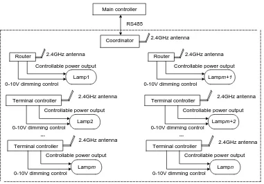
The Structure and Function of System
The system structure is shown in Figure 2, the size of the wireless network is n. The main controller can be an industrial control computer or a PLC controller, and connects with multiple wireless coordinators throughRS485 bus.
Coordinator Router
Terminal controller
Main controller RS485 Router Coordinator Terminal controller ...
Controllable power output 0-10V dimming control
The wireless network 2.4GHz antenna
2.4GHz antenna Lamp1
Controllable power output 0-10V dimming control
Lamp2
Terminal controller
2.4GHz antenna Controllable power output 0-10V dimming control
Lampm
2.4GHz antenna Router
Terminal controller
...
Controllable power output 0-10V dimming control
2.4GHz antenna
2.4GHz antenna Lampm+1
Controllable power output 0-10V dimming control
Lampm+2
Terminal controller 2.4GHz antenna Controllable power output 0-10V dimming control
[image:3.612.111.492.82.348.2]Lampn
Figure 2. The diagram of system structure.
The functions of each part of the system are as follows:
(1) The main controller runs a dimming control algorithm to generate commands for tunnel lighting control and dimming, and sends commands to each wireless node through the coordinator; collects operating status and fault information of each lamp. Meanwhile, it communicates with the tunnel power distribution system to collect power distribution parameters and complete the corresponding functions. It can also connect with other networks through the internet to form a complex network to realize remote supervision of the tunnel.
(2) The coordinator has three functions: first, receiving the command sent by the main controller or returning the lamp fault status information and the node fault status information to the main controller through RS485 bus. Secondly, creating a wireless network, and automatically modify networking parameters in the network. Lastly, communicating with each node in the network, putting out the commands of dimming, power control, and lamp fault detection
Outside brightness
Fuzzy
reasoning clarify
Fuzzy control decision
LED lamp Knowledge base
(database and rule base)
Defuzzi-fication Traffic flow
Driving speed
Fuzzy controller
Output dimming
[image:4.612.102.486.83.186.2]value
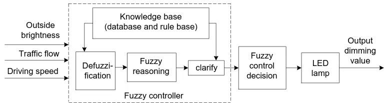
Figure 3. The model of fuzzy control algorithm.
The Design of Fuzzy Dimming Algorithm
The fuzzy control algorithm model of the system is shown in Figure 3.The main controller collects the corresponding tunnel environment information through the coordinator, such as the brightness, traffic flow and vehicle speed, and converts it into digital quantity as the input signals of the fuzzy controller. The fuzzy controller is used to analyze and eliminate the blur, and the dimming control strategy is generated accordingly. The dimming strategy information is sent to the coordinator via serial communication, and is forwarded to the wireless node by the coordinator, controlling the intelligent dimming of the lamps, or closing part of the reinforced lamps in time. Thereby, the system can realize accurate brightness change of the LED lamps.
HARDWARE AND SOFTWARE DESIGN OF SYSTEM
Hardware Design
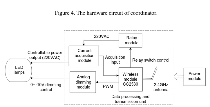
The coordinator and the wireless node are designed based on the CC2530 chip compatible with the 8051 core. The hardware circuit of the coordinator is shown in Figure 4. It consists of power module, CC230 chip and 485 communication module. The block diagram of the wireless node is shown in Figure 5. It consists of power module, relay module, current acquisition module, dimming module and CC2530 chip.
Software Design
The system needs to develop programs for the three types of nodes: coordinator, router and terminal controller, all using the functions provided by the Z-STACK
485 communication
module modulePower
Main controller
Wireless module CC2530
Data processing and transmission unit
[image:5.612.97.490.167.236.2]2.4GHz antenna UART
Figure 4. The hardware circuit of coordinator.
Wireless module CC2530 Current
acquisition
module Acquisition input
Data processing and transmission unit
Power module 2.4GHz
antenna Relay switch control
0~10V dimming control Controllable power output (220VAC) Analog dimming module Relay module PWM 220VAC LED lamps
Figure 5. The hardware circuit of wireless node.
protocol stack. The program of each type of node first initializes the system, that is, initializes the hardware abstraction layer, network layer, tasks, variables, arrays and etc[9]. Then starts the operating system, makes the system enter the loop ,and continuously traverses the task. When networking, a unique wireless network is established by the coordinator, and only wireless nodes that are consistent with the network number can join the network.
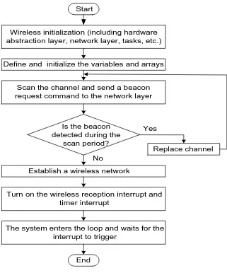
THE SOFTWARE DESIGN OF COORDINATOR
[image:5.612.114.476.237.422.2]that no other coordinators exist in the current network, then establish its own wireless network, and only one coordinator is allowed in a network. After the networking is completed, the coordinator turns on wireless reception and timed interrupt.
The wireless data reception interrupt is initiated by the node and is used to return the relevant state information of the node to the coordinator. The serial data reception interrupt is initiated by the main controller. In the interrupt service subroutine, the coordinator uses the serial port callback function to parse and process the data. The coordinator and the main controller are connected through the RS485 serial communication interface, and the standard communication protocol MODBUS RTU is used for data exchange.
Start
Define and initialize the variables and arrays Wireless initialization (including hardware abstraction layer, network layer, tasks, etc.)
Scan the channel and send a beacon request command to the network layer
Is the beacon detected during the
scan period?
Establish a wireless network No
Replace channel Yes
The system enters the loop and waits for the interrupt to trigger
Turn on the wireless reception interrupt and timer interrupt
[image:6.612.153.474.261.647.2]End
THE SOFTWARE DESIGN OF WIRELESS NODE
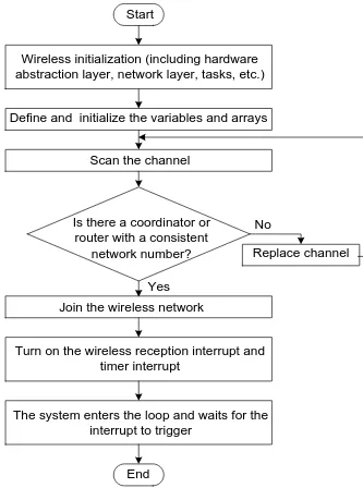
As shown in Figure 7, the main program flow of the router and the terminal controller is basically the same, and the design difference is that the router has the function of extending the wireless network and forwarding the wireless message to the terminal node.
Start
Define and initialize the variables and arrays Wireless initialization (including hardware abstraction layer, network layer, tasks, etc.)
Scan the channel
Is there a coordinator or router with a consistent
network number?
Join the wireless network
No
Replace channel
Yes
The system enters the loop and waits for the interrupt to trigger
Turn on the wireless reception interrupt and timer interrupt
[image:7.612.144.477.188.647.2]End
After the router is powered on, the system is initialized first. Then program scans the channel for a coordinator or router that matches the network number. After the network access is successful, the coordinator assigns the network short address to the routing node [9]. When the routing node receives the network access request sent by the terminal, it first confirms the legal network access information of the terminal node, and then establishes a network connection with it. The router adopts the interrupt mode to receive and parse the wireless data sent by the coordinator, and responds differently according to different functional requirements, such as dimming or switch control of the connected lamp, and detection of the fault status information of the lamp. The fault and positioning information are fed back to the coordinator. If the wireless data is forwarded to the corresponding terminal node, the router searches the forwarding list of the network frame for the address of the next hop node and forwards the wireless information.
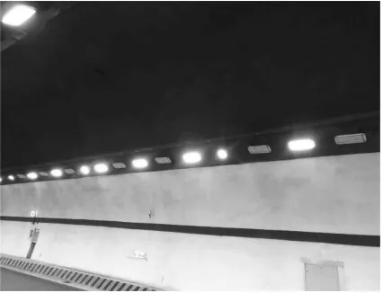
Figure 8. Application example of intelligent control system.
[image:8.612.191.404.494.657.2]THE APPLICATION EXAMPLE OF SYSTEM
The design of the system is based on the left hole of a tunnel in Yi-Lou highway in Hunan Province. The total length of the tunnel is 397 meters, and the two lanes are unidirectional. The actual lighting layout scene in the tunnel is shown in Figure 8. The system consists of a main controller, a coordinator, several routers, terminal controllers and LED lamps. The main controller is installed in the tunnel electronic control room, and each lamp is equipped with one wireless node.
In practical applications, the tunnel lamps are divided into a reinforced lighting group and a basic lighting group. The actual operation effect of the system in the tunnel is shown in Figure 9. It realizes the single-lamp power switch control (interval lighting) and intelligent dimming of the enhanced lighting group, thus creating a reasonable tunnel visual environment, ensuring safe driving of the vehicle, and achieving the purpose of energy saving.
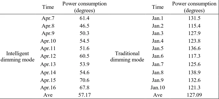
[image:9.612.107.489.382.556.2]The tunnel was rebuilt from January 20 to March 30, 2018, the energy consumption monitoring for all lighting circuits was achieved. The lighting energy consumption data in the intelligent dimming control mode and the traditional lighting mode are shown in Tab.1. The data acquisition conditions in the intelligent dimming mode are that: main controller runs the fuzzy dimming control algorithm;
TABLE I. TUNNEL LIGHTING ENERGY CONSUNPTION DATA COLLECTION TABLE.
Time Power consumption
(degrees) Time
Power consumption (degrees)
Intelligent dimming mode
Apr.7 61.4
Traditional dimming mode
Jan.1 131.5
Apr.8 46.5 Jan.2 115.4
Apr.9 50.3 Jan.3 127.9
Apr.10 54.5 Jan.4 123.8
Apr.11 51.6 Jan.5 136.6
Apr.12 60.5 Jan.6 117.3
Apr.13 53.9 Jan.7 125.6
Apr.14 54.6 Jan.8 138.9
Apr.15 70.6 Jan.9 132.6
Apr.16 67.8 Jan.10 121.3
Ave 57.17 Ave 127.09
As shown in TABLEI, it can be concluded that the difference of lighting energy consumption between tunnel intelligent dimming and traditional dimming mode can be worked out:
(127.09 − 57.17)/127.09 = 55.02% (1)
That is, the system can work well and realize energy saving of tunnel lighting, and the energy saving rate reaches 55.02%.
CONCLUSIONS
Based on wireless technology, this paper designs a tunnel lighting intelligent control system. According to the characteristics of the tunnel and its actual functional requirements, coordinator, router and terminal controller are designed and developed to realize the switch control and smooth adjustment of brightness of the lamps in the tunnel. The single-lamp control function is used to control the group switching of different types of tunnel lamps, thereby simplifying the power supply and distribution system of tunnel lighting. That wireless dimming replaces wired dimming, can eliminate the need to deploy dimming cables, reduce the construction cost of highway tunnel lighting systems and shorten the construction cycle of lighting systems. In addition, the fault detection function of the lamp based on wireless network technology can replace the manual troubleshooting, which can improve the fault maintenance efficiency of tunnel lighting system, and reduce the risk of tunnel safety operation. The actual operation effect of the system verifies the effectiveness and reliability of the system. The system can significantly reduce the tunnel lighting energy consumption and ensure the tunnel traffic safety. This tunnel lighting intelligent control system possesses practical engineering application value.
ACKNOWLEDGMENTS
The Project Sponsored by the Transportation Science &Technology of Hunan Province in China (No. 2017-10).
REFERENCES
1. Ning Li, Xiaodong Wang, Jiande Wu, et al. Using of Genetic Algorithms in Highway Tunnel Lighting Intelligent Optimization [J]. Journal of Central South University: Natural Science, 2013 (S1): 342-345.
3. H Yi, Changbin L, Aiguo W, et al. LED Lighting Control System in Tunnel Based on Intelligent Illumination Curve[C]//Intelligent Computation Technology and Automation (ICICTA), 2012 Fifth International Conference on. IEEE, 2012: 698-701.
4. G Pan, H Ke. Study on Energy-Saving Lighting of Optical Catheter System at Road Tunnel Threshold Zone[C]//Photonics and Optoelectronics, 2012 Symposium on. IEEE, 2012: 1-3. 5. L Qin, L Dong, W Xu, et al. A “Vehicle in, Light Brightens; Vehicle out, Light Darkens”
Energy-Saving Control System of Highway Tunnel Lighting [J]. Tunnelling and Underground Space Technology, 2017, 66: 147-156.Underground Space Technology, 2017, 66: 147-156. 6. Haiyan Sun, Wei Chen. Design and Implementation of Intelligent System Based on ZigBee
Wireless Sensor Network [J]. Modern Electronics Technology, 2017, 40(11): 183-186. 7. Lidong Zhang, Li Qin, et al. Design and Implementation of Intelligent Monitoring Software
System for Tunnel Lighting [J]. Journal of Highway and Transportation Research and Development, 2017, 34(10): 92-99.
8. Parise G, Martirano L, Parise L. The Energetic Impact of the Lighting System in the Road Tunnels [J]. IEEE Transactions on Industry Applications, 2016, 52(2): 1175-1183.