Design of Motor Control System Based on
Wireless Sensor Network
https://doi.org/10.3991/ijoe.v14i10.9311
Herong Yuan(*)
Nanjing Polytechnic Institute, Nanjing, China
[email protected] Jingbin Song
Changzhou Vocational Institute of Mechatronic Technology, Changzhou, China
Abstract—More and more modern devices are controlled by miniature spe-cial motors. But many existing miniature spespe-cial motors are using mostly inde-pendent test methods through wire communication. In this paper, starting from the requirements of motor testing and the situation of workshop environment, a motor measurement and control system based on wireless sensor network is pro-posed and designed. This paper elaborates the relevant technical analysis and specific implementation of TT & C module, wireless terminal, wireless router, wireless gateway and host computer measurement and control module. At last, the test function and effect of the system are explained according to the test sam-ples. The reliability and stability of the system are verified through reliability analysis.
Keywords—motor control system, wireless sensor network, electrical measure-ment and control, wireless communication
1
Introduction
In the workshop production line, the motor control link is adopted to detect the qual-ity of motor. The testing equipment is mostly semi-automatic equipment. They are usu-ally independent and comprehensive testing fixtures, mainly including motor test fix-tures and PC [3]. The motor test fixfix-tures has the function of motor control and project detection, and the test results are sent to the computer software of the PC by wired communication. Besides, the power supply and communication line of the equipment are connected by cable, which requires that the detection workshop should plan the equipment position and cable direction in advance. At the same time, when the motor is detected, each device needs special test workers' operation, and each test table is independent. Then the administrator will merge and report the motor detection data stored in different PC machines. The traditional micro motor detection equipment is not suitable for additional and mobile testing equipment because of the need to arrange cable. As each test fixtures needs a PC, the utilization rate of the PC machine is low, the equipment is large and the test operation is more complex. In addition, each device needs personnel participation in the test process, increasing the cost of testing man-power. Meanwhile, the test data of different equipment need to be artificially integrated, which is not conducive to management. Gradually, the equipment cable is easy to dam-age, and equipment fault inquiry and maintenance are more complicated.
Wireless communication is one of the fastest developing technologies in the field of communication in recent years. It mainly uses the characteristics that electromagnetic waves can radiate and propagate in space, and it is used as the carrier of information to exchange data in space [4].
The industrial wireless network is a kind of wireless sensor network which is equipped with equipment control, data acquisition and other functions for industrial field. It uses wireless communication technology to subtract the cables needed for com-munication in the cable industrial network, making the system easy to use, maintain and expand. In the cable industry network, the typical cable installation cost is between 130 and 650 dollars per meter. If the wireless communication mode is adopted, the installation cost of the cable can be reduced by 20-80% [7-8]. Actually, industrial wire-less network has a broad application prospect because of its own characteristics, includ-ing savinclud-ing the cost of controllinclud-ing network, reducinclud-ing the complexity of equipment in-stallation, improving the extensibility and maintainability of the equipment, reducing the limitation of the space area of the system and so on. The emergence of industrial wireless network enriches the way of information transmission in the field of industrial control. It is a revolutionary technology to reduce the cost of system design, to improve the category of industrial application and system maintainability.
According to the complexity of testing items, workshops can be divided into two kinds of testing methods. One is for complex situations of equipment and environment, such as high temperature resistance, high voltage resistance, high frequency noise in-terference, torque measurement and control, etc. In this case, the testing items are usu-ally independent, and each item is detected by pipeline. After the current project is qualified, it will be transferred to the next item. In this way, the detection equipment has high pertinence, precision and reliability, but the detection efficiency and space utilization ratio are relatively low. The other one is for testing items such as coil current, speed, angle detection and out of step detection. In general, comprehensive test fixtures are usually used for testing.
The traditional integrated test fixtures are used to detect the requirements of the test-ing items, taktest-ing the micro stepper motor of vehicle as an example, which mainly in-volves the detection of the coil current, running speed and out of step detection. The traditional integrated test fixture does not contain torque measurement and control de-vice, so it can not accurately measure the performance of the motor with load, and the detection method of stepper motor's out-of-step problem is still in the experimental stage.
2
Overall Plan of System
2.1 System measurement and control technology
The system measurement and control technology mainly includes four parts: the mi-cro stepper motor measurement and control system, the simulated load loading tech-nology, the torque detection technology and the angle detection technology.
Micro stepper motor measurement and control technology mainly involves micro stepper motor drive, coil current detection, speed detection and other technologies.
between the input interface of the motor and the output interface of the digital pulse signal source. The design of the drive circuit must be combined with the technical pa-rameters of the stepper motor, there are three papa-rameters that are closely related to drive circuit design, which are briefly described as follows:
• Unloaded starting frequency:The pulse frequency which enables the stepper motor
to start normally under unloaded condition is called unloaded starting frequency. When the frequency of the driving pulse is higher than the unloaded starting fre-quency, the motor may not start normally and howl.
• Inherent step angle of motor: The inherent step angle of the motor refers to the
angle that the driver sends a pulse signal to make the stepper motor turn over. In actual work, the step angle is related to the specific design of the driver.
• The phase number of the stepper motor: Usually the stepper motor has different
number of coils. Currently, there are two phase, three phase, four phase and five phase stepper motors commonly used. The stepper motor has different coil phases, so the step angle is different.
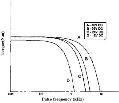
The torque frequency characteristics of several typical stepper motors are shown in Figure 1, and the output torque of the stepper motor, driven by the high frequency rate pulse, is rapidly decreasing. In practical applications, a high frequency drive pulse is often needed to drive the step to make the motor run steadily at the specified rate. If the driving pulse is directly controlled by the driving pulse at the starting frequency, the step motor is easily lost and even can’t be started at all. When the stepper motor starts with load, the starting frequency of the stepper motor is lower than that of the unloaded condition, which is more likely to cause the motor to lose step and block the rotor. After the stepper motor completes the normal operation task, if the control driver stops send-ing the drivsend-ing pulse at a certain moment, it is easy to cause the overshoot of the motor because of the inertia of the motor rotor or the load.
The frequency drive mode is usually used to improve the stability of the stepper motor in carrying and running at high speed, , and the typical pulse frequency control curve is shown in Figure 2. The frequency control of the stepper motor is to start with a driving pulse lower than the starting frequency, and then increase the driving fre-quency to the operating frefre-quency according to a certain rule. In the same way, the driving frequency is reduced in accordance with a certain rule in the deceleration to avoid the out of step or overshoot [9-10].
taken into full consideration. Thus the detection method has the advantages of low de-tection cost and simple structure.
Fig. 1. Torque-Frequency characteristic of typical stepper motor
Fig. 2. Lifting frequency pulse frequency curve
2.2 ZigBee wireless network
The wireless network composed of ZigBee technology is a wireless personal area network (LR-WPAN) with low rate, low loss and flexible throughput. The most basic unit of the network is equipment. According to the size of the device function, it can be divided into FFD and RFD. FFD devices can communicate with multiple RFD devices or FFD devices at the same time, but RFD devices can only communicate with one FFD device. There are three types of device in ZigBee wireless network: coordinator, router and terminal device. The primary task of the coordinator is to establish the wireless network and manage the network equipment, and in the process of networking, it has the function of distributing network address and receiving wireless data. The router is responsible for discovering the network, which has the functions of managing the net-work equipment, maintaining the information of the routing table, and forwarding the data. Usually, the terminal equipment has the function of discovering the network and receiving the wireless data. In fact, each device in the ZigBee network has a unique 64 bit IEEE address, and the coordinator assigns a short address of 16 bits for each device. The device can communicate with a 64 bit IEEE address or a 16 bit short address in the network. Since each network in multiple ZigBee networks has a uniquely identified network address (PANID), the device can communicate in different ZigBee networks based on PANID and 16 bit short addresses [11].
ZigBee wireless network topology is divided into three structures: star, tree and mesh, the characteristics of each of them are as follows.
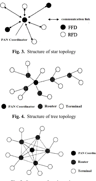
• Star topology: The star topology is characterized by the presence of coordinator as the only network management device in the network, and the topology is shown in Figure 3. The coordinator is a full function device (FFD), which is responsible for the creation, maintenance and management of the network. The other devices can choose FFD or reduced function device (RFD) as terminals, but it is important to note that the terminal devices only have network and data transceiver functions, and do not participate in network management. Since the communication between any two uncoordinator devices in a star topology must be forwarded by the coordinator, the structure is more suitable for small area communication, such as home automa-tion, medical care and so on.
• Tree topology: The tree topology contains router devices and only one coordinator
contrast, in the tree network topology, the router devices can be added to the network by the same type of device to form a multilevel tree cluster network structure, mak-ing the radio network radiation wider than the star network topology, so it is espe-cially suitable to be used in large distribution areas.
• Mesh topology: Similarly, there are coordinators, routers and terminal devices in
mesh topology, whose topology is shown in Figure 5. Compared with the tree topol-ogy network, any two devices in mesh topoltopol-ogy can communicate with each other in the wireless radiation range, so the network structure has strong variability and does not need to be determined in the establishment of the network. At the same time, the coordinator needs to be able to maintain network management and routers, so its storage capacity, computing power, complexity, and cost requirements are higher compared to other topologies [13]. As a result, the network topology has strong network ability and coverage. Therefore, it is more suitable for occasions with wide distribution of device and high networking capability, such as industrial con-trol, intelligent agriculture and so on.
Fig. 3. Structure of star topology
Fig. 4. Structure of tree topology
2.3 System design scheme
The system designed in this paper is mainly applied to the quality detection link in the motor production line of electronics workshops. According to the needs of the step motor detection in the workshop, the following important factors should be considered. 1.System generality. Because of the diversity of micro stepping motor products for workshop production, different types of motor are usually different in motor shape, motor drive voltage, driving frequency and other parameters. In order to improve the utilization ratio of the equipment, the testing system will be compatible with the testing requirements of different specifications of motor products.
2.Testing items and technical indicators
• Loading and testing of simulated load. The system can provide continuous and
controllable torque on the rotating shaft of the motor to realize the function de-mand of analog load and plugging. The loading range of torque is 0~300N. cm and the precision is 1N.cm. It can detect and display the motor load in real time, and its detection accuracy is higher than that of the simulated load device.
• Angle detection. The system has the function of angle detection, which can
lo-cate and measure the rotation angle of the motor shaft, and the precision of angle detection is 0.1
• Current detection. The system has the motor coil current detection function,
which can display the current in the form of graphic curve and detect the current peak, plug current and other information, further, the precision of current detec-tion is 1mA.
• Speed detection. The system has the function of motor speed detection, which
can display the speed information of the motor with load.
3.Necessary function. The necessary functions include configuration of the motor de-tection item and the product information, the out-of-step dede-tection, the configuration of the product's factory status, the edited product label interface, the display and storage of the test results.
4.Reliability of system. The system has high reliability, it can work for more than 24 hours in a single time, and the detection speed less than 30s/ per station. Addition-ally, the sample detection through the measurement and control equipment has good repeatability and reproducibility.
5.(Other requirements. In addition to meeting the functional requirements and relia-ble operation of system, the following requirements should be met as far as possirelia-ble: first, reduce the complexity of system installation and maintenance; second, improve the utilization of the old equipment, the utilization of workshop space and the exten-sibility of the equipment; third, improve the efficiency of the workshop and save the human resources; finally, provide the compatibility of the database with the work-shop management system, and realize the sharing of the test data.
The control strategy of decentralized detection and centralized management is adopted to integrate the detection data and improve the detection efficiency, in this way, the data sharing of the detection data and the workshop management system can be realized. At the same time, the use of wireless communication technology instead of the partial wired cable avoids the complexity of the workshop wiring and improves the scalability and mobility of the equipment.
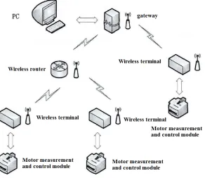
As shown in Figure 6, the overall structure of the system includes three parts: PC, wireless communication module and measurement and control module. Specifically, PC is mainly used for the control of test and control commands and the storage and display of test results. The wireless communication module is mainly used for the wire-less transmission of control commands and data. Through the analysis of the environ-ment, functional requirements and system complexity of production lines, the system selects ZigBee wireless communication technology and adopts ZigBee tree network topology, including wireless terminal, wireless routing and wireless gateway, where ZigBee wireless terminal uses the serial communication mode to exchange data with the measurement and control module, and the ZigBee wireless gateway uses the USB serial communication mode to exchange data with PC. Further, the measurement and control module is mainly used to construct the measurement and control platform and detect the performance of the micro stepping motor, including the motor drive module, the current detection module, the torque measurement module, the angle detection mod-ule, the serial communication module and the power module.
The operating principle of the system is as follows:
Firstly, ZigBee coordinator establishes the wireless network, the terminal and router device search and join the wireless network. Secondly, the system control module sends the ready state confirmation information to PC through the terminal equipment. After PC receives the ready state confirmation information, it sends and executes the meas-urement and control commands. Thirdly, after receiving the command and control com-mand of PC, the system begins to measure the stepper motor and sends the measure-ment and control information to PC via the terminal device, and then PC will display and store the results of measurement and control. At last, after testing a product, PC verifies the test data and sends qualified or unqualified information to the measurement and control module. The measurement and control module receives the qualified infor-mation and automatically begins to detect the next product; while the unqualified in-formation is received, the test procedure for unqualified products is carried out accord-ing to the requirements of the workshop.
3
System Testing and Analysis
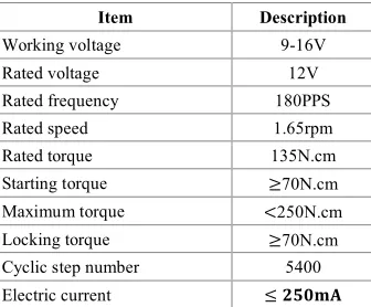
The operation and testing of the system are mainly explained by the setting, opera-tion results and reliability analysis of the stepper motor's measurement and control. The relevant parameters of the motor measurement and control system are shown in Table 1.
Table 1. Stepper motor parameters
Item Description
Working voltage 9-16V
Rated voltage 12V
Rated frequency 180PPS
Rated speed 1.65rpm
Rated torque 135N.cm
Starting torque ≥70N.cm
Maximum torque <250N.cm
Locking torque ≥70N.cm
Cyclic step number 5400
Electric current ≤ 𝟐𝟐𝟐𝟐𝟐𝟐𝟐𝟐𝟐𝟐
According to Table 1, the step motor is driven by the pulse of 12V voltage and 200Hz frequency, every 7200 driving pulses make the motor rotated for one cycle. The rated load of 135 N.cm may be applied, running current is less than 250 mA, and rated speed is 1.65 rpm.
device is turned on, then the wireless device is waiting for networking. When network-ing is successful, the measurement and control parameters of the motor can be set.
The test results show that the actual running position of the test out-of-step is 44.92°, actual end angle is 134.78°. The motor operates under the pulse drive of voltage 12V and frequency 200HZ, and there is no out-of-step phenomenon. The motor's speed, current, locked torque and locked rotor current are all within the testing standard under the condition of load.
The measurement and control system of the step motor based on wireless network is applied to the workshop production line. The reliability of its measurement and control function is closely related to the quality of the factory products. The main contents of the system reliability test are the reliability of the current detection device, the reliability of the motor measurement and control device, the reliability of wireless communica-tion, the repeatability and the stability of the system.
The reliability of wireless communication is analyzed through the packet loss situa-tion of wireless communicasitua-tion and the interference of wireless communicasitua-tion by the scene environment. In practice, wireless communication technology has a certain delay compared with wire communication. When there is a large area of metal obstacles in the scene environment, the communication quality will decline. The system adopts ZigBee application scheme with external antenna for wireless communication. Com-pared with the wireless devices without the power amplifier module, the designed wire-less devices have strong communication ability and high communication quality. It can make up the defects of the wireless network radiation range, and meet the communica-tion needs of the workshop.
4
Conclusions
5
Acknowledgments
This work is sponsored in part by QingLan Project in Jiangsu Province.
6
References
[1]Harwit, E. (2001). The Impact of WTO Membership on the Automobile Industry in China. China Quarterly, 167(167): 655-670. https://doi.org/10.1017/S0009443901000365
[2]Liu S. J. (2002). Tendency of Globalization of Automobile Industry and Its Impact on Chi-na's Automobile Industry. China Industrial Economy, 6: 20-21.
[3]Kim, W., Shin, D., Chung, C. C. (2012). The Lyapunov-based controller with a passive nonlinear observer to improve position tracking performance of microstepping in permanent magnet stepper motors. Automatica, 48(12): 3064-3074. https://doi.org/10.1016/j.automat-ica.2012.08.035
[4]Dan, S., Patriciu, A., Petrisor, D., Mazilu, D., Kavoussi, L. (2007). A New Type of Mo-tor: Pneumatic Step Motor. IEEE/ASME Transactions on Mechatronics, 12(1): 98.
https://doi.org/10.1109/TMECH.2006.886258
[5]Song, Y., Feng, Y., Ma, J., Zhang, X. (2011). Design of LED Display Control System Based on AT89C52 Single Chip Microcomputer. Journal of Computers, 6(4): 718-724.
https://doi.org/10.4304/jcp.6.4.718-724
[6]Han, S., Song, J., Zhu, X., Mok, A. K. (2009). Wi-HTest: compliance test suite for di-ag-nosing devices in real-time WirelessHART™ mesh networks. Wireless Networks, 21(6): 327-336. https://doi.org/10.1109/RTAS.2009.18
[7]Gungor, V. C., Hancke, G. P. (2009). Industrial Wireless Sensor Networks: Challeng-es, Design Principles, and Technical Approaches. IEEE Transactions on Industrial Electronics, 56(10): 4258-4265. https://doi.org/10.1109/TIE.2009.2015754
[8]Åkerberg, J., Gidlund, M., Lennvall, T., Neander, J., Björkman, M. (2011). Efficient in-tegration of secure and safety critical industrial wireless sensor networks. Eurasip Journal on Wireless Communications & Networking, 2011(1): 1-13. https://doi.org/10.1186/1687-1499-2011-100
[9]Wang, Y., Wang, W., Yang, W. T. (2008). Control System Design of Acceleration and De-celeration Curves of Stepping Motor and Its Application. Control Engineering of China, 15(5): 576-579.
[10]Bovik, A. C., Maragos, P., Quatieri, T. F. (1993). AM-FM energy detection and separa-tion in noise using multiband energy operators. Signal Processing IEEE Transactions on, 41(12): 3245-3265. https://doi.org/10.1109/78.258071
[11]Xiu, D. B., Sun, Q., Ge, C. Z., Luo, Y., Du, Y. T., Wang, Y. D., Shi, Y. B. (2013). Design of Mobile Meteorological Monitor Based on Wireless Sensor Network. Applied Me-chanics & Materials, 303-306: 938-944. https://doi.org/10.4028/www.scientific.net/AMM.303-306.938
[12]Wang, L., Li, Y., Fu, G. (2017). Design of ZigBee Wireless Communication Network Node Based on Internet of Things Cloud Platform. Computer Measurement & Control.
[13]Luo, X., Dong, M. (2013). Distributed Fault-Tolerant Detection in Wireless Sensor Net-works. Computers IEEE Transactions on, 55(1): 58-70. https://doi.org/10.1109/TC.2006.13
7
Authors
Herong Yuan received the master's degree in software engineering from Sichuan University, China in 2014. Currently, she is an experimenter at Institute of electrical and control, Nanjing Polytechnic Institute, Nanjing 210048, China. Her research inter-ests include electrical control and electrical engineering.
Jingbin Song received the Master's degree in application engineering of vehicle from The Northeast forestry university, China in 2007. Currently, he is a adjunct pro-fessor at Department of automotive engineering, Changzhou Vocational Institute of Mechatronic Technology, Changzhou 213164, China. His research interests include ve-hicle inspection and veve-hicle emission control.