In Proceeding of National conference on Advanced Manufacturing and Materials
(NAMME), Mei 2010.
SHELL MOULD WITH TREATED ORGANIC FIB
ER
Z. Harun, N. H. Kamarudin, M. S. Wahab, A. M. Ahmad Zaidi, N. A. Badarulzaman
Faculty of Mechanical and Manufacturing Engineering, University Tun Hussein Onn Malaysia, MALAYSIA.
Tel : + 607 4537744 , Fax :+ 607 4536080
E-mail:[email protected]
Abstract
In this work, the reinforcement in ceramic shell mould (for casting molten metals) treated with organic fiber (rice husk) to strengthen its body was investigated. Several testing procedures and characterization technique were carried out in order to measure the performance of the shell mould. The results show that the reinforced shell mould with organic fiber can withstand the drastic changes in temperature during pouring process without cracking mechanism (compared to the shell mould without reinforcement). The obtained results show that the shell mould with treated organic fiber gave the highest value in MOR, less cracking in SEM observation and failure with the mix mode (highly plastic and less brittle). It was also identified (from performance test) that the reinforcement technique can reduce the coated layering number of the shell mould system
Keywords: reinforced organic fiber, rice husk, cracking
mechanism,
1. Introduction
Due to the fact that investment casting process operating at high temperature condition therefore the failure of the end cast product always associated to the appearance of defect problem that caused by failure of the shell mould system. Pressure build up phenomena due to incomplete drying condition in shell mould system is one of the reasons why this situation is happened. In the present work the shell mould reinforced with organic fiber to strengthen its body and avoid cracking mechanism that lead to the failure of the shell mould. Rice husk is chosen as reinforcement in this work because it contains almost 90-100% silica element[1, 2] which has high melting
temperature[2] and at the same time can creates bonding in this brittle structure of the shell mould system.
In general, production of investment casting ceramic shell mould is a crucial part of the whole process in the investment casting industry. The failure in producing the ceramic shell mould not only leads to the defect appearance in cast component but also increase the cost of raw material and the production time. The shell mould making process firstly involves the preparation of multi component slurry that composed of fine mesh refractory filler system and a colloidal binder. Then this is followed by the dipping process of a pattern wax into the slurry, then sprinkled with coarse refractory stucco and finally dried. This method is repeated for several layers until it is achieved a required thickness.
In this work, the mould was reinforced with an organic fiber which comes from the agro waste which is continuation from the previous work[9]. The purpose of using these organic fibers are one alternative in reducing agro waste problem and also to reduce emission level that always associated to the casting industry due to the fact that this fiber is purely nature. As this organic fiber is purely comes from the plant which means it is easy to deteriorate, therefore its need a treatment to avoid this from happens[10, 11]. In this work some efforts have been done by treating this fiber using certain chemical elements regarding to the previous work [10, 11]. Previous work on the reinforced composite with treated natural fiber indicates that this procedure can improve the mechanical properties of the composite system[10, 11].
2.0 Experimental
2.1 Raw Materials and preparation of treated fiber
2.1.1 Ceramic Slurry
Ceramic slurry is a basic material to produce shell mould component. The main ingredients of this slurry are 30% colloidal silica and mulgrain flour (325 mesh) that was used in this work was produced by Akzo Nobel Asia Pte. Ltd. Taiwan Branch and were used as received. Both of these raw materials were weighed based on same ratio and composition and then mixed until it was changed into homogenous composition. At the same time the viscosity of slurry was determined using Viscosity Cup or Zahn Cup for 10seconds. Paraffin wax is the main component that typically used in industry to generate a basic shape of the mould. Wax dilution process is carried out by using Wax Melting Vat machine. Wax was heated up to 100oC to ensure the wax used is fully melting (liquid form).
2.1.2 Rice husk
Rice husk is the outer part which covering paddy and accounts for 20-25% of its weight.[12] It can be removed during rice milling and widely used mainly as fuel for heating in Indian homes and industries[1]. The raw rice husk used in this work is collected directly without any pretreatment from Kelantan. Basically, rice husk is characterized by low bulk density and high ash content (18–22% by weight). As mentioned before, the rice husk fiber is chosen as reinforcement in this work because it contains silica element which is the main component that can withstand high melting of pouring temperature and
also sintering process of the shell mould. Silicon dioxide forms the main component (90–97%) of the ash with trace amounts of CaO, MgO, K2O and Na2O [1, 2]. The melting
point of SiO2 is 1410°C-1610°C, while that of K2O and
Na2O is 350°C and 1275°C respectively[2]. It has been
suggested that at higher temperatures, the low-melting oxides fuse with silica on the surface of the rice husk char and form glassy or amorphous phases, preventing the completion of reaction[13]. Prior to use, the rice husk was ground and sieved to produce 6mm particle size. In addition, grinding of rice husks had also been recommended as a suitable surface modification form[14, 15].
The dried husks were treated chemically. It has been reported that purity of silica is highly affected from chemical treatment [16-19], than thermal treatment[20]. The rice husk was immersed chemically in 5% NaOH and 95% of water for 24 hours. Then, the rice husk was thoroughly washed by distilled water several times to remove the chemical. After that, it dried in the drying oven at 80°C for 12 hours.
2.2 Shell Mould Masking Process
MOR (Modulus of Rupture) for every layer of shell mould system 0 0.1 0.2 0.3 0.4 0.5 0.6 0.7
0 1 2 3 4 5 6 7 8 9 10 11
Layer of she ll mould
M O R v a lu e ( M P a )
With treated fiber With nontreated fiber Without Fiber 2.3 Mechanical Testing and Characterizations
MOR test is an appropriate test to measure the strength of most of brittle material that is weak in tension and strong in compression. Due to the fact that the crack propagation are too fast, causes the plastic deformation almost not exist in ceramic material and any internal disturbance can make the failure easy to happen. Therefore, three point bending test was done according to ISO 178:93 (International Standards Organization) methods by a SHIMADZU Universal Testing Machine (Model AG-1). These tests were carried out to determine of the modulus of rupture (MOR) of the layered shell mould system. For MOR testing, the samples were prepared upon a wax pattern with dimensions of 100mmx25mmx5mm thickness. Shell moulds were fired at 1000˚C for 2 hours. Then, the fired samples were observed using the Scanning electron microscopy (SEM). Micrographs of the samples were obtained by using a JEOL, JSM-638OLA.
2.4 Performance test; Metal Casting
The strength and integrity of the mould are very important factors in order to ensure the final metal part has the proper dimensions. These factors is very critical especially for manufacturing of high performance components, such as super alloy parts for aerospace industry [21]. Basically, metal casting involves heating process of metal component into liquid phase up to melting temperature, then it is poured into the mould and kept solidify at room temperature. Typically, shell mould is sintered in the furnace at 1000˚C for 2 hours to ensure that the mold is ready for metal casting process. The moulds become susceptible to bulging and cracking when they are filled with the molten metal. Bulging can alter the dimensions of the mould, thereby causing undesirable variation in the component being cast. Meanwhile, cracking could result in failure of the mould as the molten material runs out of it [21]. Therefore, the used of reinforcement material is introduced in this work to overcome the above mentioned problems. In this work, the new shell moulds were prepared using the minimum coating layers (4 layers) which have tendency to break especially for the shell mould without fiber.
3. RESULTS AND DISCUSSION
3.1 MOR (Modulus of Rupture) of rice husk fiber
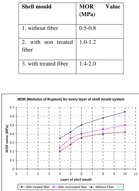
The results of MOR tests on fired samples of shell mould for four layers are listed in Table 1. Shell
[image:3.612.353.590.344.670.2]mould with treated fiber shows the highest MOR value than shell mould with non treated fiber and shell mould without fiber. Shell mould with treated fiber exhibited higher strength than that of the shell mould with non treated fiber giving a range about 1.0MPa to 1.2MPa and 1.4MPa to 2.0MPa, respectively. Shell mould without fiber has the lowest value which has the range of MOR from 0.5MPa to 0.8MPa. The results indicate that the shell mould with treated organic fiber has strong bonding that can prevent the thermal expansion during pouring and also shrinkage mechanism during cooling of the shell mould. In fact, the results also revealed that the reinforcement technique using agrowaste materials not only can increase the strength of the mould body but also lead to the using of fewer coats in layering process of shell mould. The comparison of MOR (Modulus of Rupture) value for three different shell mould system was shown in Figure 1.
Table 1
MOR (Modulus of Rupture) Test result with 4 layers
Shell mould MOR Value (MPa)
1. without fiber 0.5-0.8
2. with non treated fiber
1.0-1.2
3. with treated fiber 1.4-2.0
Figure1. Comparison of MOR (Modulus of Rapture) for every layer of shell mould system
The observations of microstructures using SEM of fired body were shown in Figures 2 to 5.
Figure2: Higher magnification of SEM micrograph image of surface on shell mould with treated fiber
Figure3: Higher magnification of SEM micrograph image of surface on shell mould with non treated fiber
Figure4: SEM micrograph image of surface on shell mould with treated fiber
Figure5: SEM micrograph image of surface on shell mould with non treated fiber
Shell mould with non treated organic fiber contains a bigger size of porosity compared to the shell mould of treated fiber as shown in the mentioned figures. The overall microstructure of the treated fiber also shows no appearance of the small crack and the structure is more homogenous. The shell mould with fibers (treated and non treated) also show it can withstand high melting temperature of molten metal during the pouring process. (As shown in Figures 6 and 7)
surface on shell mould with treated and non treated fiber. Figure6: The mould reinforced with treated organic fiber (on the left) and the mould without fiber with the existence of crack before pouring process (on the right).
Figure7: After pouring molten metal, the mould with treated organic fiber still can withstand high temperature of the molten metal.
4.0 CONCLUSION
Overall, shell mould reinforced with organic fiber proved can increase the strength of this brittle mould structure which can avoid the mould from splitting during the firing and also pouring stage. This reinforcement technique also leads to the using of fewer coat of shell mould system which is very important factor in order to reduce the production cost.
REFERENCES