MODELING, ANALYSIS AND IFO CONTROL METHOD FOR
CSI FED 3 PHASE INDUCTION MOTOR DRIVE
1M. ARUL PRASANNA, 2DR. V. RAJASEKARAN, 3DR. I. GERALD CHRISTOPHER RAJ
4N. PANNEER SELVAM
1Assistant Professor, Department of EEE, PSNA College of Engineering & Technology, Dindigul, India. 2Professor & Head, Department of EEE, PSNA College of Engineering & Technology, Dindigul, India, 3Associate Professor, Department of EEE, PSNA College of Engineering & Technology, Dindigul, India. 4Assistant Professor, Department of EEE, Vickram College of Engineering & Technology, Sivaganga India
E-mail: [email protected],[email protected],[email protected],
ABSTRACT
This Paper presents the review of theoretical concepts used in simulation and hardware implementation of Indirect Field oriented (IFO) Control for CSI fed Induction Motor (IM) drives. IFOC is the most common Induction Motor drive because of its use of moderate amounts of parameter information to give a commendable performance. This is achieved in the absence of high level sophistication and by successfully operating at very low speed (including zero speed startup). In this paper, the IM model for current fed Rotor Field Oriented (RFO) control method is presented. Indirect Field oriented (IFO) controller and rotor flux estimator are designed. The Simulink implementation of IFOC to CSI fed IM drive is presented. Transient response analysis tables and other simulation results are presented and discussed. The most important contributions in this paper are Simulation structure of IM model in rotor flux frame, rotor flux estimator using current and speed are developed and implemented in MATLAB-Simulink, Simulation structure and implementation of IFOC to CSI fed IM drive is presented, Dynamic performance of the controller is investigated; Tabular form of the simulation results is also presented. Brief experimental results are presented for IFOC method for speed control using TMS320F2812 DSP based hardware setup.
Keywords: Induction Motor, IFOC, RFO, VSI, CSI, MATLAB/Simulink.
1. INTRODUCTION
As in the case of DC drives, independent control of the flux and torque is possible in AC drives. The stator current phasor resolves into two components. One of them, the component along the rotor flux linkage is field producing current which requires the position of the rotor flux linkages at every instant. This is dynamic in state unlike in the DC motor. If this is available, then the control of AC motor is very similar to that of separately excited DC motor [1]. The control is achieved in field coordinates; hence, the name of this control strategy is Field Oriented Control (FOC). As it relates to the phasor control of the rotor flux linkages, it is also known as vector control.
FOC schemes are classified according to mode in which the field angle is obtained [10]. If the field angle is calculated by using terminal voltages and currents or hall sensors or flux sensing winding, it is known as direct FOC or DFOC. The field angle can
measurement and partial estimation of machine parameters known as IFOC. The direct method of FOC is difficult to operate successfully at very low frequency (including zero speed) as voltage signals are very low. In industrial applications, vector drives are often required to operate from zero speed (including zero speed start-up). On the other hand, IFOC removes the dependence of the controller accuracy on temperature. This type of controller is therefore considerably more robust than the previous one. The motor torque can be accurately controlled even down to zero speed operation. Moreover, the controller is completely independent of rotor time constant variations. So, IFOC is very popular in industrial applications.
ISSN: 1992-8645 www.jatit.org E-ISSN: 1817-3195
frame is presented. The rotor flux orientation is also obtained. In the low speed region, the rotor flux components can be synthesized more easily with the help of speed and current signals. Design of indirect vector controller and rotor flux estimator is discussed. Implementation of IFOC to CSI fed IM drive and transient response analysis of other simulation results are also discussed.
2.MODELING OF IM FOR CURRENT FED RFO CONTROL
This section describes the modeling of Current source Inverter fed 3phase Induction motor drive with Rotor Flux Oriented controller. The rotor equations in Synchronous Reference frame of the IM containing flux linkages as variables are given by [3] as follows,
0
0 (1)
where
then the Equation (1) becomes
0
0 (2)
The resultant rotor flux linkage, also known as the rotor flux linkages phasor, is assumed to be on the direct axis to reduce the number of variables in the equations by one. Moreover, it relates to reality that rotor flux linkages are a single variable. Hence, aligning d axis with rotor flux phasor yields
(3)
0 (4)
0 (5)
Substituting Equations (3) to (5) in (2) results in the new rotor equations
0
0 (6)
The rotor currents in terms of the stator currents are derived from Equation (6) as
(7)
1
1
(8)
(9)
Where is the Magnetizing Inductance and is the Rotor Leakage Inductance, also the q and d axes currents are relabeled as torque ( ) and flux producing () components of the stator-current phasor, respectively. denotes rotor time constant. Equation (8) resembles the field equation in a separately-excited DC motor, whose time constant is usually dominant and slow. This is applicable to IM rotor time constant too.
Similarly, by the same substitution of the rotor currents from (7) into torque expression, the electromagnetic torque is derived as
322
322
(10)
Where the torque constant is defined as
322
(11)
3.DESIGN OF IFO CONTROLLER
The IFO controller was designed using the concepts of [4], [5] and [8]. From that the stator-current phasor is the phasor sum of the d and q axis stator currents in Synchronous Reference frame and it is given as
(12)
and the dq axes (2) to (3) abc phase current relationship is obtained from
௦
ௗ௦
2 3
cos cos2
3 cos4
3
sin sin 2
3 ! sin 4
3 !"# # # $
௦
௦
௦"
# # # $
(13)
Can be written as
%&' (14)
Where
(15)
%&' % & ' (16)
()* 23
cos cos23 cos+23
sin sin
2
3 sin+
2 3 "#
# # $
(17)
Where %, & and ' are the three phase stator currents. Note that the elements in the T matrix are cosinusoidal functions of electrical angle, . The electrical field angle in this case is that of the rotor flux-linkages phasor and is obtained as the sum of the rotor and slip angles:
(18)
and the slip angle is obtained by integrating the slip speed and is given as
(19)
IFO controller, developed from these derivations, accepts the torque and flux requests and generates the torque and flux producing components of the stator-current phasor and the slip-angle commands [11]. The command values are denoted with asterisks throughout this paper. From Equations (8), (9) and (11) the command values of , and are obtained as follows
∗ ∗
∗
2
3 2
∗
∗
(20)
∗ 1
∗
(21)
∗
∗
∗ (22)
The command slip angle, ∗ is generated by integrating ∗. The torque angle command is obtained as the arctangent of ∗and ∗. The field angle is obtained by summing the command slip angle and rotor angle. With the torque and flux producing components of the stator current commands and rotor field angle, the qd axes current commands (abc phase current commands) are obtained as follows. The relevant steps involved in the realization of the IFO controller are as follows:
!
∗
∗" #
cos sin
sin cos ) *
∗
∗
+ (23)
and
,
-.%∗
&∗ '∗/0
0 0 1
./
,
-.∗
∗
0 /0 0 0 1
(24)
Where
./
,
-. 1 0 1
1
2 √32 1
1
2 √32 1/0
0 0 0 1
(25)
By using Equations (23) to (25), the stator q and d axes and abc current commands are derived as
∗ |∗| sin ∗
(26)
∗ |∗| cos ∗
%∗ |∗| sin ∗
&∗ |∗| sin ∗ 243
'∗ |∗| sin ∗243
Where
ISSN: 1992-8645 www.jatit.org E-ISSN: 1817-3195
The implementation of IFOC on a CSI fed IM is shown in Figures 1 and 2. The torque command
i0∗is generated as a function of the speed error signal generally processed through a PI controller. The flux command i1∗can be given directly or as a function of speed. The rotor position θ2 can be measured with an encoder and converted into necessary digital information for feedback [12].
There has been a substantial amount of research in the development of rotor flux observers for field orientation that are compensated for variations in parameters by their feedback corrections. Digital implementation of integrators for the estimation of rotor flux of an IM from the stator voltages and stator currents poses problems associated with the offset in the sensor amplifiers [9]. Traditional low-pass filters can replace the integrator.
So, in this paper, rotor flux estimated using low pass filter is described. The instantaneous flux linkage can be computed using the measured d axis stator current using Equation (28), which is referred to as the current model.
λ୰ L୫iୢୱ
1 τ୰ (28)
4.SIMULATION IMPLEMENTATION OF IFOC
The block diagram of the simulation model for the IFOC strategy is shown in Figure 3.
Fig.3.Simulink Implementation of IFOC method
ωe
Te*
ids* or if*
Calculator
iqs* or iT*
Calculator Flux
Reference
ωref
ω
r to ωm
Theta* Calculator
Rotor Flux Calculator
iabc to idq
3Phase to 2 Phase Conversion
Idq*to iabc*
2Phase to 3 Phase Conversion
Current Source Inverter
Induction Motor
Speed Calculator +
-
ωr
ωr
ωr
Te
Load Torque TL
iabc
iabc*
Speed Controller
ωr ωm
Phir id
Fig.2.Stator current generator. ݏ݈∗
݂∗ ܶ∗
ܽݏ∗
ܾݏ∗
ܿݏ∗
ݎ
∫ ݏ݈∗
ݐܽ݊−1݅ܶ ∗
݂݅∗ ܶ
∗
ݏ∗
ݎ ݅ݏ∗=ට(݅ܶ∗)2+ (݂݅∗)2|ݏ
∗|
ܽݏ∗=| ݏ∗|ݏ∗
ܾݏ∗=| ݏ∗|( ݏ∗−
2
3)
ܿݏ∗=| ݏ∗|( ݏ∗+
2
3)
Fig.1.Simplified diagram for IFOC method.
ܶ݁∗
݅ܿݏ∗ ܾ݅ݏ∗ ݅ܽݏ∗
߱ݎ∗ ߣݎ∗
CSI
IM ݅ݏ PWM Switching
Logic
߱ݎ Rotor Speed Regulator
Stator Current Generator
݅ܶ∗ 4
3ܲ ܶ݁∗ ߣݎ∗ ܮݎ ܮ݉
݂݅∗ ൬1 +ܮݎ
ܴݎ൰ ߣݎ∗ ܮ݉
ܴݎܮ݉ ܮݎ
݅ܶ∗ ߣݎ∗ ߱ݏ݈∗
ߠݎ
The mechanical speed of the rotor is compared to its command value and the speed error is fed into a PI controller which produces the command torque value. The command values for torque, rotor flux and rotor position are used to determine i0∗, i1∗, and slip speed ω34∗ using Equations (20), (21) and (22). By satisfying these equations, the rotor flux is held constant and is properly oriented with the synchronously rotating reference frame while the q-axis component of the stator current is adjusted to match the load torque requirements. The slip speed is integrated and then added to the angular position of the rotor to obtain field orientation. The i0∗, i1∗
and Theta∗ calculator blocks which performed the
calculations discussed above, are shown in Figure 3
The command values for the qd-axis components of the stator current are in the synchronously rotating reference frame and the corresponding field orientations are fed into the qd to abc (2 Phase to 3 Phase) conversion block where the stator currents are transformed from the synchronously rotating qd0 reference frame to the abc reference frame in two transformations. The first transformation converts the qd-axis component stator currents from the synchronously rotating qd0 reference frame to the stationary qd0 reference frame, whereas, in the second transformation the stator currents are transformed from the stationary qd0 reference frame to abc reference frame. The 2 Phase to 3 Phase conversion block which performs the conversion discussed above is shown in Figure 3. The transformation Equation (13) used in the simulation block is derived from [3]. The theoretical concepts of IFOC method for CSI fed IM drive discussed through simulation using the Simulink toolbox of MATLAB. The detailed simulations results are presented in the next section.
5.RESULTS DISCUSSIONS
5.1. Simulation Results
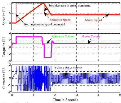
[image:5.595.309.504.531.697.2]The response of the drive when step changes in speed command is shown in Figures 4, 5, and 6 and the response of the drive when step changes in torque command is shown in Figure 7. From the figures, it can be seen that the torque response of the motor is rapid and precise. In fact, IFOC makes IM respond to a change in load torque in less than 0.25 seconds.
Fig. 6 Speed, torque and current response of IFOC drive when change in speed command at Full load 0
.5 1
S
p
ee
d
i
n
P
U
-4 -2 0 2 4
T
o
rq
u
e
in
P
U
0 1 2 3 4 5
-2 -1 0 1 2
Time in Seconds
C
u
rr
en
t
in
P
U
Step increase in sp eed command Reference Sp eed Step decrease in sp eed command
M otor Sp eed
M otor Torque Reference Torque
a p hase stator current
Fig.5.Speed, torque and current response of IFOC drive
when change in speed command at constant load 0
.5 1
S
p
ee
d
i
n
P
U
-4 -2 0 2 4
T
o
rq
u
e
in
P
U
0 1 2 3 4 5
-2 -1 0 1 2
Time in Seconds
C
u
rr
en
t
in
P
U
Reference Torque M otor Torque Reference Sp eed
Step decrease in sp eed command
M otor Sp eed
a p hase stator current
Step increase in sp eed command
Fig.4.Speed, torque and current response of IFOC drive
when change in speed command at no load
0 .5 1
S
p
ee
d
i
n
P
U
-4 -2 0 2 4
To
rq
u
e
in
P
U
0 1 2 3 4 5
-2 -1 0 1 2
Time in Seconds
C
u
rr
en
t
in
P
U
Reference Torque M otor Torque
a phase stator current Step decrease in speed command
M otor Speed Step increase in speed command
ISSN: 1992-8645 www.jatit.org E-ISSN: 1817-3195
[image:6.595.81.514.65.760.2]
The IFOC simulation used in ode45 (Dormand-Prince) integration method is run for 5 seconds of simulation time during which the speed command is varied from 0 to its rated speed. The load torque applied to the motor is also varied between no load and full load. The speed, torque and current are plotted against time for different loading conditions. Tables 1 and 2 depict the tabular form of simulation results for easy analysis.
Table 1: Dynamic performance of IFOC drive: Step change in motor speed
Motor parameters
Step change in speed command from Zero to rated speed
No load Constant load Full load
t ୰ (ms) t ୱ (ms) M ୮ (%) t ୰ (ms) t ୱ (ms) M ୮ (%) t ୰ (ms) t ୱ (ms) M ୮ (%) Motor
current 76 903 225 84 1299 273 62 1390 164
Motor
speed 467 976 136 421 1124 136 401 1385 105
Motor
torque 79 957 293 87 1298 240 99 1444 185
Table 2: Dynamic performance of IFOC drive: Step change in motor torque
Motor parameters
Step change in torque command from No load to full Load
t
୰(ms) tୱ(ms) M୮(%)
Motor
current 52 208 238
Motor
speed 118 262 3
Motor
torque 58 209 140
5.2. Experimental Result
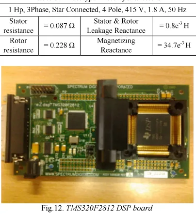
Brief experimental results are presented for IFOC method (speed control) using TMS320F2812 DSP based hardware setup. Figures 11 and 12 show the laboratory prototype hardware setup. Prototype Fig.10. Speed, torque and current response of IFOC drive
when change in speed from 0 to double the rated speed 0 .5 1 1.5 2 S p ee d in P U -4 -2 0 2 4 T o rq u e in PU
0 1 2 3 4 5
-2 -1 0 1 2
Time in Seconds
C u rr en t in P U
Step decrease in speed command
Step increase in speed command
Reference Speed
Motor Speed
Step decrease in torque command Reference Torque
Step increase in torque command Motor Torque
[image:6.595.292.517.74.292.2]a phase Stator current
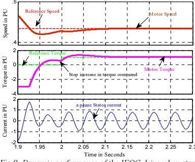
Fig.9. Dynamic performance of the IFOC drive when step increase in +ve torque command
.4 .5 S p ee d in P U -4 -2 0 2 T o rq u e in P U
1.9 1.95 2 2.05 2.1 2.15 2.2 2.25 2.3
-2 -1 0 1 2
Time in Seconds
C u rr en t in P U
Reference Sp eed
M otor Sp eed
a p hase Stator current
M otor Torque
Reference Torque
[image:6.595.91.288.331.499.2]Step increase in torque command
Fig.8. Dynamic performance of the IFOC drive when change in speed command
0 .5 1 S p ee d in P U -4 -2 0 2 4 To rq u e in P U
0.2 0.4 0.6 0.8 1 1.2
-2 -1 0 1 2
Time in Sec onds
C u rr en t in P U
M otor Torque
Reference Torque
M otor Speed
Reference Speed
[image:6.595.304.507.437.651.2]Step increase in speed command
Fig.7. Speed, torque and current response of IFOC drive when change in torque command at full load 0 .5 1 S pe ed i n P U -4 -2 0 2 4 T o rq u e in P U
0 1 2 3 4 5
-2 -1 0 1 2
Time in Seconds
Cu rr en t in P U
Step increase in speed command
Reference Speed
Step decrease in speed command
M otor Speed
Motor Torque Reference Torque
Step increase in torque command Step decrease in torque command
[image:6.595.93.285.537.697.2]processor contains the program that is downloaded to it form the computer. The clock speed of the DSP is 150 MHz, and it is capable of 32-bit operations. The onboard available flash memory is 2.048 Mb. It was created specifically for motor control operation, and therefore Park’s and Clark’s transformations are conveniently built in. Another convenient feature is that it has sixteen 12-bit ADC pins that allow for a high degree of precision while taking many possible measurements.
Table 3: Prototype Motor parameters 1 Hp, 3Phase, Star Connected, 4 Pole, 415 V, 1.8 A, 50 Hz
Stator
resistance = 0.087 Ω
Stator & Rotor
Leakage Reactance = 0.8e
-3 H
Rotor
resistance = 0.228 Ω
Magnetizing
Reactance = 34.7e
-3 H
Figure 13 and 15 shows simulated speed response of laboratory prototype IM, under different loading conditions. Figure 14 and 16 shows experimental speed response, which is taken from the hardware setup. It is clear from Figures 13 to 16 that experimental and simulation results are similar. Due to highly expensive cost of sensors it is difficult to take other hardware results and parameters related to the simulated waveforms.
Fig.16. Computer plotted Experimental speed response of prototype IM under constant load
Fig.15. Simulated speed response of prototype IM under constant load
0 1 2 3 4 5
-300 -200 -100 0 100 200 300
Time in Seconds
S
p
e
e
d
i
n
r
a
d
ia
n
s
/s
e
c
o
n
d
s
[image:7.595.90.290.250.406.2]Reference Sp eed M otor Speed
Fig.14. Experimental speed response of prototype IM under no load
Fig. 13. Simulated speed response of prototype IM under no load
0 1 2 3 4 5
-300 -200 -100 0 100 200 300
Time in Seconds
S
p
e
e
d
i
n
r
a
d
ia
n
s
/s
e
c
o
n
d
s
Reference Sp eed M otor Sp eed
Fig.12.TMS320F2812 DSP board
[image:7.595.306.505.390.719.2] [image:7.595.89.291.438.659.2]ISSN: 1992-8645 www.jatit.org E-ISSN: 1817-3195
6. CONCLUSION
This paper contains a review of theoretical concepts used in simulation and implementation of IFOC for CSI fed IM drives, in which stator current follows the stator current references closely as in [1] has discussed a rotor flux based reference frame control method for PWM CSI fed IM [13], [14]. In this work, a rotor flux based reference frame control method for PWM CSI fed IM with simplified simulation circuits have been developed in which the motor speed and torque follow the references closely. Figure 7 shows the dynamic response of speed, torque and currents of IFOC drive when there is a change in speed - torque command at full load. From the waveforms, it is evident that the motor speed and torque follow their reference values closely. Figure 10 shows the dynamic response of the drive for the above rated speed applications.
With this type of control method, wide range of speed control is possible for different loading conditions. From the simulation results, refer Table 1 and 2, it is evident that during step change in speed command, the transient response in current, speed and torque in terms of rise and settling time are high compared to the transient response during the step change in torque command. In contrast, there is a decrease in the overshoot of current for full load case. It is clear from Figures 13 to 16 that experimental and simulation results are similar however, since the instantaneous motor inductance values are not predictable during running condition the experimental speed curve is not that much linear as compared to the simulated speed response.
REFERENCES:
[1] Blaschke, F. “The principle of field-orientation as applied to the transvector closed-loop control system for rotating-field machines”, Siemens Rev., Vol. 34, pp. 217–220, 1972. [2] Marian P. Kazmierkowski, “Control
Philosophies of PWM Inverter-Fed Induction Motors” International Conference on Industrial Electronics, Control and Instrumentation, IECON 97, Vol.1, pp.16-26, 1997.
[3]Krause, P. C., Wasynczuk, O. and Sudhoff S. D. “Analysis of Electric Machines and Drive Systems”, Wiley-IEEE Press, New York, 2002.
[4] Vas, P. Electrical Machines and Drives. London, U.K.: Oxford Univ. Press, 1992. [5] Mika Salo and HeikkiTuusa,
“Vector-controlled PWM current-source-inverter-fed induction motor drive with a new stator current control method”, IEEE Trans. Ind. Electron., Vol. 52, No. 2, pp. 523-531, 2005.
[6] Bin wu, “High-Power Converters and AC Drives”, IEEE Press, A John Wiley & Sons, Inc., Publication, 2006.
[7] Bimal K. Bose, “Modern Power Electronics and AC Drives”, Prentice Hall, New Jersy, 2002.
[8] Mohamed S. Zaky, “Stability Analysis of Speed and Stator Resistance Estimators for Sensorless Induction Motor Drives”, IEEE IEEE Trans. Ind. Electron., Vol. 59, NO. 2, February 2012.
[9] M. S. Zaky, M. M. Khater, S. S. Shokralla, and H. A. Yasin, “Wide speed range estimation with online parameter identification schemes of sensorless induction motor drives,” IEEE Trans. Ind. Electron., vol. 56, no. 5, pp. 1699– 1707, May 2009.
[10] Jose Andres Santisteban and Richard M. Stephan, “Vector Control Methods for Induction Machines: An Overview,” IEEE Transactions on Education, Vol. 44, No. 2, pp. 170-175, 2001
[11] Cruz, C. Gallegos, M.A., Alvarez, R. and Pazos, F. “Comparison Of Several Nonlinear Controllers For Induction Motors”, IEEE International Power Electronics Conference-CIEP, pp. 134-139, 2004.
[12] Alfredo Munoz-Garcia, Thomas A. Lipo and Donald W. Novotny, “A New Induction Motor V/f Control Method Capable of High-Performance Regulation at Low Speeds”, IEEE Trans. Ind. Appl., Vol. 34, No. 4, pp.813-821, 1998.
[13] Bin Wu, Shaahi B. Dewan, and Gordon R. Slemon, “PWM CSI Inverter Induction Motor Drives”, IEEE Trans. Ind. Appl., Vol. 28, No. 1, pp. 64-71, 1992.
[14] Holmes, D.G. and Lipo, T.A. “Pulse Width Modulation for Power Converters”, published by IEEE Press - Wiley-Interscience, 2003. [15] MummadiVeerachary, “Optimal Control