INTELLIGENT PREDICTION AND
PREVENTION OF VEHICLE ROLLOVER
USING FLQG REGULATOR
1BINDA.M.B, 2DR.M.RAJARAM 1Research Scholar, Sathyabama University, Chennai
2Vice Chancellor, Anna University, Chennai.
ABSTRACT
In this paper, we present a novel methodology for predicting and prevention of vehicle rollover model and control strategies which is suitable for preventing the untripped rollovers that was to be caused in vehicle. For vehicles that are deemed to be susceptible to wheel-lift off, various control strategies are implemented by earlier researchers. In this work, we propose a method for rollover prediction and prevention based on the combination of fuzzy logic with Gaussian controller which does not require such accurate contact information. The validity of the proposed methodology is proved, and it is used to realize rollover prediction and prevention in the direction of the roll. The primary assumption in this implementation is that the vehicle is equipped with a conventional fuzzy based controller system.
Keywords: Rollover, Ga Tuned Pid Controller, Pid Controller
I. INTRODUCTION
Rollover in a vehicle occurs when the vehicle flips over. There are two categories of rollover called tripped and untripped rollover. Tripped rollover is the most common type, and occurs when the car has started to skid, hits an obstacle, and finally flips over. Untripped rollover is induced by the driver, either by extreme maneuvers, or in panic situations. Before a rollover can occur, the vehicles wheels on one of the side must lose its road contact which occurs a wheel lift off situation. The wheel lift off situation is chosen as the critical situation to be avoided. If wheel lift off is prevented, then rollover is prevented as well. A schematic representation of rollover model is shown in figure 1.
The main advantage of our proposed approach is: purely based on the safety Concerns and Understanding the Physics behind Rollover that are occurred in SUV vehicles.
Driver and his/her reactions to the world is the parameter of significant importance to the study of vehicle rollover prediction and control. Various mathematical representations of the human driver have models been developed by earlier researchers for the prediction and
avoidance of rollover [7]. Among them, no one predicted and removed the rollover caused in a vehicle effectively.
Therefore, it is important to overcome the major drawbacks that are present in the prediction and avoidance of rollover that was occurred in the vehicles.
There are two options to the automobile designer wishing to design a vehicle incapable of rollover design a vehicle chassis or chassis control system very conservatively to mitigate driver inputs that push the vehicle to the limits of safe handling and instability, or modify the driver’s input to the vehicle such that instability is avoided. This paper seeks to contribute significantly to the rollover mitigation methods that directly modify the driver’s steering command in a way such that the driver does not realize the effect of the controller. However, in order to properly accomplish this goal, the physics behind vehicle rollover must first be understood.
2. RELATED WORKS
Rollover prevention is a topical area of research in the automotive industry (see, for example, the rollover section at http://www.safercar.gov/ for a good introduction to the problem) and several studies have recently been published. Relevant publications include that of Palkovics et al. [8], where they proposed the ROP (Roll-Over Prevention) system for use in commercial trucks making use of the wheel slip difference on the two sides of the axles to estimate the tire lift-off prior to rollover.
Wielenga [9] suggested the ARB (Anti Roll Braking) system utilizing braking of the individual front wheel outside the turn or the full front axle instead of the full braking action. The suggested control system is based on lateral acceleration thresholds and/or tire lift-off sensors in the form of simple contact switches.
Chen et al. [10] suggested using an estimated TTR (Time To Rollover) metric as an early indicator for the rollover threat. When TTR is less than a certain preset threshold value for the particular vehicle under interest, they utilized differential braking to prevent rollover.
A number of metrics based on geometric principles have been developed for stability mea-surement. Researchers in mobile robotics have recognised that the location of the vehicle centre of gravity (c.g.) relative to the wheel–terrain contact points is critical to vehicle sta-bility. The stability polygon (or support pattern) is defined as the convex hull of the polygon formed by wheel– terrain contact points projected onto a horizontal plane [1]. An early geo-metric measure defined stable vehicle configurations as those where the horizontal projection of the vehicle c.g. lies within this polygon [2].
A stability margin was then defined based on the shortest distance from the projected c.g. to a side of the polygon. Improvements to this measure were proposed [3,4]. However, this metric ignores the effects of changes in c.g. height and the destabilising influence of vehicle dynamic effects. It should be noted that a common geometric stability metric used in vehicle design is the static stability factor, which is computed as the ratio of vehicle width to c.g. height [5].
In [13] several methods for detecting vehicle rollover were tested. The purpose of the tests was to find a method for detecting impending vehicle rollover that will activate active chassis subsystems when needed and minimize unnecessary activations of the chassis control systems. First, estimates obtained from the use of single sensors were examined. A lateral acceleration sensor, roll rate sensor, and suspension relative position sensor were all used to obtain estimates of the vehicle roll angle.
Ackermann et al. and Odenthal et al. [11], [12] proposed a robust active steering controller, as well as a combination of active steering and emergency braking controllers. They utilized a continuous-time active steering controller based on roll rate measurement. They also suggested the use of a static Load Transfer Ratio (LTRs) which is based on lateral acceleration measurement; this was utilized as a criterion to activate the emergency steering and braking controllers.
3. ROLLOVER PREVENTION METHOD BY MITIGATION CONTROL
Due to a sudden application of the lateral acceleration, the running vehicle’s response tends to overshoot. As a result, the inner wheels may be lifted off during the steering when the applied acceleration is lower than the nominal limited value is as follows
(
ysin )
x x x
mh a
g
k
c
I
I
I
φ φ
φ
φ
φ
φ
=
+
−
−
&
&&
(1)
Assume sin߶ ≈ ߶, and after applying Laplace transform law to the aforementioned differential equation, the following new equation has been established:
2
( )
( )
.
( ) ( ) ( ) ( )
x x
y x x x
k mgh I mh I
s
a s s c I s k mgh I k mgh I
φ
φ φ φ
φ −
=
+ + − −
(2)
Where the angular frequency is
1/ 2
(
)
n
k
φmgh I
xω
=
−
(3)1/ 2
2 (
)
xc
k
mgh I
φ
φ
ξ
=
−
(4)
When a unit step function lateral acceleration is given, the overshoot is
2
exp( )
(1 )
P
M ξπ
ξ = −
−
(5)
At this point, we found that the first part of (2) explains vehicle dynamics, whereas the second part defines the vehicle steady state.
Figure.1. Vehicle Rollover Model.
4. PID AND FLQG CONTROLLER
A PID controller calculates error value .The controller attempts to minimize the error by adjusting the process control inputs. The PID controller calculation (algorithm) has three terms of control: the proportional, integral and derivative values denoted by P, I and D. Where P is the present error, I is the accumulation of past errors and D is the prediction of future errors.
A PID controller will be called a PI, PD, P or I controller in the absence of the respective control actions. PI controllers are fairly common, eliminates the steady state error.
A PID controller has proportional, integral and derivative terms that can be represented in transfer function form as
K(s)=Kp+Ki/s+Kds (6)
Kp: means proportional gain, a tuning parameter, Ki: means Integral gain, a tuning parameter, Kd: means Derivative gain, a tuning parameter
By tuning the above PID controller gains, the controller can provide control action especially for specific design requirements. The proportional term is proportional to the current error. The integral term (Ki) is proportional to both the magnitude of the error and the duration of the error. It (when added to the proportional term) accelerates the movement of the process near to the set point and usually eliminates the residual steady-state error that may occur with a proportional only controller.
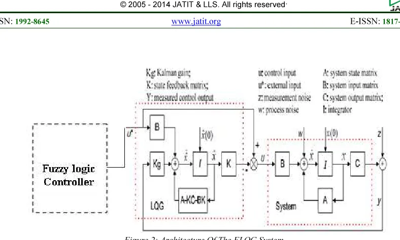
Fuzzy logic based linear quadratic Gaussian (FLQG) controller Design
In this paper, a fuzzy logic based linear quadratic Gaussian controller was proposed. The Fuzzy logic based Linear quadratic Gaussian (FLQG) controller design for the rollover model mostly focuses on three parts based on the basic principle of the basic LQG controller mentioned above: (1) optimal linear quadratic estimator (LQE) design; (2) optimal linear quadratic Gaussian regular (LQR) design; (3) system integration along with the fuzzy logic. Together with the linear quadratic estimator and the linear quadratic Gaussian regular (LQR), the fuzzy logic solves the problem of linear-quadratic-Gaussian control. Figure 2 shows the architecture of the FLQG system
LQG Optimal Controller
The LQG control signal u is a state feedback described below:
u= -Kx (7)
Where, the K vector is derived from the solution of a Riccati Algebraic Equation. u can be derived from the minimization of the quadratic cost function:
0
[ T( ) c( ) ( ) T( ) ( ) ( )]c k
J x k q k x k u k r k u k
∞
=
=
∑
+(8)
where qc(k) and rc(k) are the weight matrices, i.e.,
Figure 2: Architecture Of The FLQG System
Design of a Fuzzy linear quadratic estimator
The Kalman filter is a feasible estimation approach that can fuse multiple sensory measurements to provide relatively accurate results. The Kalman filter can minimize the mean of the squared error from a series of noisy measurements. In this proposed methodology, fuzzy logic based controller is used to control the flow of executions that are fed towards the Kalman filter present in the LQG. The steps for controlling and fedding the input to the estimator is as follows
Fuzzy Logic
Fuzzy Logic (FL) is a multi-valued logic that allows intermediate values to be defined between conventional evaluations like true/false, yes/no or high/low. Fuzzy systems are an alternative to traditional notions of set membership and logic. The training and testing fuzzy logic is to map the input pattern with target output data. For this purpose, the inbuilt-in function has to prepare a membership table and finally a set of numbers are stored. During testing, the membership function is used to test the pattern.
In this FLQG controller, the membership values generated in the membership table is fed as input towards the normal LQG inorder to reduce the flow of executions.
Training Fuzzy Logic for prediction
Step 1: Read the pattern (quadratic Gaussian and its target value).
Step 2: Create Fuzzy membership function based on the patterns.
Step 3: Match the membership values with the controller values.
Step 4: Process with target values.
Step 5: Obtain final weights.
Testing Fuzzy Logic for prediction Step 1: Input a target (rollover) values.
Step 2: Process with Fuzzy membership function.
Step 5: Find the Gaussian value to which the pattern belongs.
Step 4: Obtain estimated target values. Step 5: Classify and predict the rollover.
Design of Fuzzy linear quadratic regulator
• Optimization method
The control strategy is characterized by the control configuration illustrated in Figure 2 The realization of the optimal control strategy depends on the state estimation and the control law. Considering the roll model control problem, the control law is optimized by minimizing the cost function to guarantee control objectives which are a minimal position error and using as little control effort as possible.
• Control law
The control values can be obtained by the optimization method mentioned above. In order to calculate this, the steepest descent method was applied, which is an iterative method, being simple implementation, but with slow convergence.
The Matlab codes were made and simulation has been conducted to (1) select the controller’s parameters, like the cost function’s sensitivity to dynamic effects and the stop criterion, (2) obtain the cost function and the control law. The cost function has been close to zero after 5 iterations.
• System integration
System integration is a significant step in designing LQG controller after designing the optimal estimate and configurating the optimal controller. Figure 3 shows the system closed-loop configuration.
Figure 3: System Closed-Loop Configuration
5 SIMULATION RESULTS
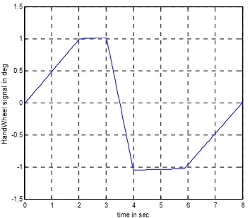
In order to verify the proposed mitigation control, simulation tests are conducted according to NHTSA’s Fishhook 1a test, and the steering maneuver pattern is shown in Figure 4.
Note that the wild fluctuations occur when the hand wheel angle rate changes rapidly, especially within the time ranges of [2s, 3s] and [4s, 6s] given in the below figure 6
Integral action
Sensor Noise Scope
Reference Step
Plant /Actuator
in_1 out_1
out_2 Output Constraint
Mux LQR Gain
(matrix )
K* u Mux
Kalman state estimator x' = Ax+Bu y = Cx+Du
1 s Feedforward gain
-K-Figure 6: Simulation Diagram For Roll Model
0 0.1 0.2 0.3 0.4 0.5 0.6 0.7 0.8 0
0.2 0.4 0.6 0.8 1 1.2 1.4
Step Response
Time (sec)
Am
p
litu
d
e
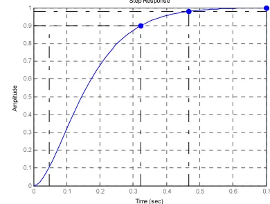
Figure 7: ߶ Versus Ay Transient Response For Ξ=0.71
In theory, the overshoot is nearby zero if the damping ratio equals one. However, as we know, high roll stiffness and roll damping cost vehicle ride comfort. For a balance purpose, we assigned the compromised damping ratio ߦ at a normal factory-set value.
There are many factors that can influence the roll stiffness ݇Φ and the roll damping ܿΦ, such as springs, dampers, and bushings.
0 0.1 0.2 0.3 0.4 0.5 0.6 0.7
0 0.1 0.2 0.3 0.4 0.5 0.6 0.7 0.8 0.9 1
Step Response
Time (sec)
A
m
p
litu
d
[image:5.595.89.503.53.751.2]e
Figure 5: ߶ Versus Ay Transient Response For Ξ=0.95
A specified brand of midsize SUV was used in this study, of which the relevant parameters are shown in Appendix.
With the rollover model and vehicle parameters, we achieved the damping ratio of the original vehicle, ߦ
[image:5.595.311.506.443.590.2]the roll stiffness ݇Φ and the roll damping ܿΦ must be increased simultaneously. Otherwise, the damping ratio ߦ may be decreased.
With the rollover model and vehicle parameters, we improve the damping ratio of the vehicle, ߦ = 0.95, and the overshoot value of the roll angle at 0.71% as shown in Figure 5.
0 1 2 3 4 5 6 7 8
-1.5 -1 -0.5 0 0.5 1 1.5
time in sec
H
a
n
d
W
h
e
e
l
s
ig
n
a
l
in
d
e
[image:6.595.105.282.225.379.2]g
Figure 4: Fishhook 1a Maneuver
6. CONCLUSION
The main purpose of this research work is to propose a novel methodology for predicting and prevention when a vehicle may be at risk for wheel-lift prior to sliding. Additionally, multiple control strategies were combined with the fuzzy logic inorder to mitigate the vehicle rollover. To investigate the vehicle transient and steady states, an improved rollover model combined with the fuzzy logic was established in this study. Simulation results indicated a decreased overshoot of the roll angle and a better confined steady value. An optimal controller for a rollover model has been combined with the fuzzy controller which is designed in Matlab simulation to implement a predictive control to the vehicle roll over. The Kalman estimate was applied to train the system output and the numeric optimization method was used to test the cost function.
REFERENCES
[1] R.B. McGhee and A.A. Frank, On the stability properties of quadruped creeping gait, Math. Biosci. 3(2) (1968), pp. 331–351.
[2] R.B. McGhee and G.I. Iswandhi, Adaptive locomotion of a multilegged robot over
rough terrain, IEEE Trans. On Syst. Man Cybernet. SMC-9(4) (1979), pp. 176–182
[3] S. Sugano, Q. Huang, and I. Kato, Stability criteria in controlling mobile robotic systems,
IEEE/RSJ International Workshop on
Intelligent Robots and Systems, Yokohama, Japan, July 1993, pp. 832–838.
[4] J.K. Davidson and G. Schweitzer, A mechanics-based computer algorithm for displaying the margin of static stability in four-legged
vehicles, Trans. ASME J. Mech. Design 112
(1990), pp. 480–487.
[5] J.P. Chrstos and D.A. Guenther, The
measurement of static rollover metrics, SAE
Transactions no. 920582, 1992.
[7] V. Cherian, R. Shenoy, A. Stothert, J. Shriver, J. Ghidella, and T. D.Gillespie, “Model-Based Besign of a SUV anti-rollover control system,” SAE Paper No. 2008-01-0579, 2008.
[8] Palkovics L., Semsey A` and Gerum E., “Roll-over prevention system for commercial vehicles-additional sensorless function of the electronic brake system”, Vehicle System
Dynamics, Vol. 4, pp. 285-297, 1999.
[9] Wielenga T.J., “A method for reducing on-road rollovers: anti-rollover braking”, SAE Paper
No. 1999-01-0123, 1999.
[10] Chen B. and Peng H., “Differential-braking-based rollover prevention for sport utility vehicles with humanin- the-loop evaluations”, Vehicle System Dynamics, Vol. 36, pp. 359-389, 2001.
[11] Ackermann J. and Odenthal D., “Robust steering control for active rollover avoidance of vehicles with elevated center of gravity”,
Proceedings of International Conference on
Advances in Vehicle Control and Safety,
Amiens, France, 1998.
[12] Odenthal D., B¨unte T. and Ackermann J., “Nonlinear steering and braking control for vehicle rollover avoidance”, Proceedings of
European Control Conference, Karlsruhe,
Germany, 1999.
[13] Aleksander Hac, T.B., and John Martens,
Detection of Vehicle Rollover. SAE,
NOMENCLATURE
Parameters Definition
ݒx Longitudinal velocity (body-fixed frame)
߱r Yaw rate (angular rate about vertical axis)
m total mass of the vehicle
Izz Inertia about the vertical axis
a front-axle-to-CG distance
b rear-axle-to-CG distance
L Track of vehicle
t Width of vehicle
β Side Slip angle of the vehicle body
k1 Front cornering stiffness
k2 Rear cornering stiffness
δf Front steering angle
ܨy1 lateral force over the front tire
ܨy2 lateral force over the rear tire
ܨn1 normal force over the left wheel
ܨn2 normal force over the right wheel
߶ roll angle
φ
&
roll rateφ
&&
body roll accelerationܽy lateral acceleration
߱̇r yaw acceleration
ܫz Inertia about the yaw moment
ܫx roll moment of vehicle inertia
ߙ1 slip angles of front tires
ߙ2 slip angles of rear tires
h0 height of the vehicle’s center of gravity (CG) standing above the ground level
h distance between the
vehicle CG and the assumed roll axis
ܶ width of the vehicle track
Δh and Δܶ deformation of suspension and tire
݇Φ total roll stiffness