© 2016, IRJET ISO 9001:2008 Certified Journal Page 474
EXPERIMENTAL ANALYSIS OF HEAT TRANSFER ENHANCEMENT IN A
DOUBLE PIPE HEAT EXCHANGER
USING INSERTED ROTOR ASSEMBLED STRAND
Sanjay P. Govindani
1, Dr. M. Basavaraj
21M-Tech Student ,Department of Mechanical Engineering , BIT Ballarpur, Dist. Chandrapur, Maharashtra, India
2
Professor, Dept. of Mechanical Engineering, BIT Ballarpur, Dist. Chandrapur, Maharashtra, India
---***---Abstract -
This project describes the experimental work on heat transfer augmentation in the double pipe heat exchanger using a new kind of insert called Rotor-assembled strand. Inserts when placed in the path of the flow of liquid, create a high degree of turbulence resulting in an increase in the heat transfer rate and the pressure drop. The heat transfer rate and pressure drop in a rotor assembled strand inserted tube will be measured using water as a working fluid. The work includes the determination of friction factor and heat transfer coefficient for rotor assembled strand insert. The experiment will be first conducted on a plain tube and then tube with the insert. The results of both the experiment will be tallied and the changes in friction factor, Nusselt number, pressure drop and heat transfer coefficient will be calculated. The results of rotor assembled strand having different rotors will be compared with the values for the smooth tube. The correlations of Nusselt number and friction factor as function of Reynolds number and Prandtl number will be determined through multivariant linear normal regression.Key Words:
Heat exchanger, heat transfer coefficient,
pressure drop, rotor assembled strand, friction factor,
dependency
1. INTRODUCTION
Heat exchangers have several industrial and engineering applications. The design procedure of heat exchangers is quite complicated, as it needs exact analysis of heat transfer rate and pressure drop estimations apart from issues such as long term performance and the economic aspect of the equipment. Whenever inserts are used for the heat transfer enhancement along with the increase in the heat transfer rate, the pressure drop also increases. This increase in pressure drop increases the pumping cost.
Therefore any augmentation device should optimize between the benefits due to the increased heat transfer coefficient and the higher cost involved because of the increased frictional losses. Swirl flow devices form an important group of passive augmentation methods in which rotor insert is one of the most important members of this group. Tubes with rotor insert have been used as one of the passive heat transfer enhancement techniques and are the most widely used tubes in several heat transfer applications; for example, heat recovery processes, air conditioning and refrigeration systems, and chemical reactors.
2.
RELATED WORK
Paisarn Naphon et al. [1] investigated the heat transfer characteristics and the pressure drop of the horizontal concentric tube with twisted wires brush inserts. The plain tube with full-length twisted wires brush and regularly spaced twisted wires brush with 30 cm spacer length inserts were tested. Cold and hot water were used as working fluids for counter flow configuration, respectively. The effect of twisted wires density, inlet fluid temperature, and relevant parameters on heat transfer characteristics and pressure drop were studied. It was found that the twisted wire brush inserts have a large effect on the enhancement of heat transfer, however, the pressure drops also increase.
© 2016, IRJET ISO 9001:2008 Certified Journal Page 475 Nusselt number which was valid for both water and
nanofluid flowing in circular plain tube and with tape inserts.
M.M.K. Bhuiya et al. [4] carried out experimental study on the heat transfer performance and friction factor characteristics in a circular tube using twisted wire brush inserts. The study was conducted for flow in turbulent region. The results indicated that the presence of twisted wire brush inserts led to a large effect on the enhancement of heat transfer with corresponding increase in friction factor for the plain tube. It was also found that there was considerable increase in Nusselt number value with increasing Reynolds number.
Rotor-assembled strand was first promoted by Yang et al. [21] in 2005. As a new type of passive insert, rotor-assembled strand has advantages over other techniques. Its merits have been proven by laboratory and commercial test, which will be introduced sequentially. The experiment in this paper is based on the fifth generation of rotor-assembled strand which has evolved with rotor material and geometry optimized.
3. ROTOR-ASSEMBLED STRAND
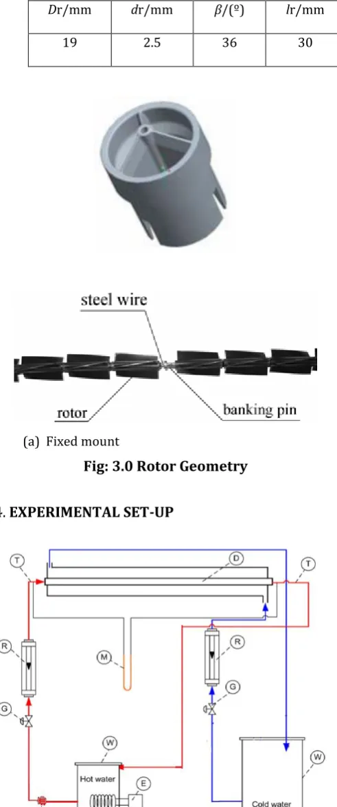
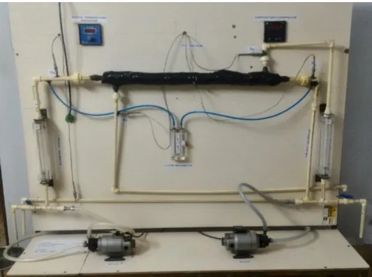
Rotor-assembled strand consists of four basic elements. They are rotors, steel wire, banking pins, and fixed mounts. Rotors are the functional elements, which will rotate under certain flush of mass flow rate to obtain heat transfer enhancement and online automatic cleaning. Plastic PC (polycarbonate, 1.42 g·cm-3) is used for the injection molding of rotors. PC has a density very close to water so that plastic rotors can almost suspend in still water, which is helpful for the automatic centering of rotors in a tube. Some important geometry parameters of a rotor are listed in Table 3.1. Dr is rotor diameter, dr is centre bore diameter, lr is rotor length, β is rotor pitch angle. The mass of rotor is 1.895 g. Steel wire is stretched straight to infix the centre bore of rotors for holding them in the centric line of a tube. Banking pins are fixed on the steel wire to hold rotors from axial displacement. The number of rotors assembled between two adjacent banking pins typically ranges from 5 to 25 while 12 rotors are used in this study. Two fixed mounts are fitted at both end of a tube to stretch the steel wire and mount rotor assembled strand to the tube as shown in Fig. a. Fixed mounts and rotors-assembled strand inserts used in this experiment are individually shown in Figs. 1 (a) and 1 (b). The rotors rotate at different revs depending on varying water flow rates.
Table 3.1 Rotor geometry parameters
Dr/mm dr/mm β/(º) lr/mm
19 2.5 36 30
[image:2.595.313.559.112.700.2]
(a) Fixed mount
(b) InsertFig: 3.0 Rotor Geometry
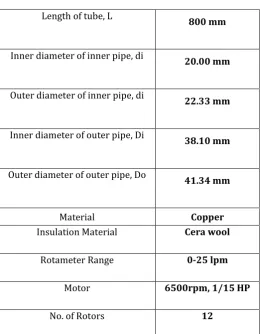
© 2016, IRJET ISO 9001:2008 Certified Journal Page 476 (D) Double pipe heat exchanger, (E) Electrical heater, (M)
U-Tube Manometer, (G) Globe valve, (R) Rotameter, (T) Thermocouples, (W) Water tank and (P) Motor
Sketch of a Bare pipe
Sketch of Rotor assembled strand mounted to tube
Fabricated Set up Model
Rotors
The layout of experimental setup is shown in figure. It consists of two concentric tubes in which hot water flows through the tube and cold water flows in annulus. The outer tube is insulated with asbestos rope and cera wool to minimize the heat loss to surroundings. Two calibrated crystal rotameters having flow ranges of 0-25 LPM are used to measure the cold and hot water flow rates. The inlet and outlet temperatures of the fluid in the tube and the annulus were measured using K-type thermocouples. The experimental set up is constructed and fabricated with great care. The set consists of water tank, pump, control valve, rotameter, heating coils, nicrome wire, thermocouples, U-tube manometer and rotor assembled strand (insert).
The water is heated using a water heater of 2 kW and the desired temperature is controlled with the temperature controller. After complete the fabrication of the experimental setup. Firstly I fill the water tank by using the tap water and then start the water pump. Set the current and voltage range in ammeter and voltmeter respectively so that it gives the uniform heat flux to the tube at wall temperature range of 500C to 510C. And now
with setting the flow rate of the working fluid at 4 lpm, 6 lpm, 8 lpm, 10 lpm and 12 lpm. The setup would be run continuously till the steady state achieve. After achieving the steady states I take the reading of temperature at the inlet and outlet of tube without using any inserts i.e. smooth tube. And also take the reading of tube surface wall temperatures by using digital temperature controller. Take the reading of pressure drop across the test tube section by using the U-tube manometer. The experimental procedure repeated with changing the valve of the inlet working fluid at different flow rate, till the steady state is achieved. After achieving steady state in smooth tube the same experimental procedure is repeated rotor assembled strand.
[image:3.595.37.304.517.716.2]© 2016, IRJET ISO 9001:2008 Certified Journal Page 477 Case I: Experimentation on test tube without using any
inserts.
Case II: Experimentation on test tube with rotor assembled strand
[image:4.595.32.293.225.560.2]4.1 Design Parameters
TABLE 4.1: SPECIFICATIONS OF DOUBLE PIPE
HEAT EXCHANGER
Length of tube, L 800 mm
Inner diameter of inner pipe, di 20.00 mm
Outer diameter of inner pipe, di 22.33 mm
Inner diameter of outer pipe, Di 38.10 mm
Outer diameter of outer pipe, Do 41.34 mm
Material Copper
Insulation Material Cera wool
Rotameter Range 0-25 lpm
Motor 6500rpm, 1/15 HP
No. of Rotors 12
5.
DATA COLLECTION AND ANALYSIS
The data was collected for plain tube as well tube with rotor inserts. The different flow rates for cold water and hot water are taken for counter flow heat exchanger. The heat transfer rate for cold water in the test section, Qc, can be expressed as,
Qc = mc * Cpc * (Tco- Tci)
where, mc is the flow rate of cold water, Cpc is the specific
heat of water, Tco and Tci are outlet and inlet cold water
temperatures respectively. The heat transfer rate for hot water in the test section, Qh, can be expressed as,
Qh = mh * Cph * (Thi– Tho)
where, mh is the flow rate of hot water, Cph is the specific
heat of water, Tho and Thi are outlet and inlet hot water
temperatures respectively. All the fluid thermophysical properties are calculated at the average of inlet and outlet hot fluid temperatures. The average heat transfer rate obtained by is calculated for hot and cold water which is used to calculate the inner convective heat transfer coefficient. The thermal equilibrium test showed that the heat transfer rate on cold side is less than heat transfer rate obtained for hot water. This indicates that there are some heat losses on the outer surface of test section. The average heat transfer rate, Qavg is determined as follows,
Q
avg=
For fluid flows in a concentric tube heat exchanger, the heat transfer coefficient, hi is calculated from
Qavg = Ui * Ai * ΔTLMTD
Where Ai = π di L
∆Tm=
The tube-side heat transfer coefficient hi is then determined using
= +
where the annulus side heat transfer coefficient (ho) is estimated by using the
correlation of Dittus—Boelter [35] :
Nuo = = 0.023 * Re0.8 * Pr0.4
Dh
= D
i- d
oThe Reynolds number is based on the different flow rate at the inlet of the test
section.
© 2016, IRJET ISO 9001:2008 Certified Journal Page 478 Thus the value of Nusselt number can be found out by,
Nu = 0.023 * Re0.8 * Pr0.4
Value of friction factor can be calculated from
F =
Pressure drop is determined by
ΔP = ρ * g * h
[image:5.595.309.561.77.294.2]6. Result And Discussion
Fig. 6.1 Nusselt Number vs Reynolds Number
From the Fig. 6.1, it is observed that there is increase in Nusselt number with Reynolds number. As Reynolds number increases the water flow will cause more turbulence due to which heat transfer rate will increase. As heat transfer coefficient is directly proportional to Nusselt number, N u= h D h/ K i.e increase in heat transfer
[image:5.595.38.288.324.507.2]coefficient increases the Nusselt number. From fig 6.1 it is observed that maximum Nusselt number is obtained for insert when cold water flow is more than hot water flow and minimum Nusselt number is obtained for smooth tube without using any inserts type.
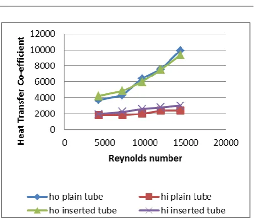
Fig. 6.2 Heat Transfer Coefficient vs Reynolds Number
From the Fig. 6.2, it is observed that the heat transfer coefficient increases with increase in Reynolds number. As Reynolds number increases, the water flow will cause more turbulence, so due to which the heat transfer rate will increase. From the Fig. 6.2 it is observed that the tube without using any insert gives less heat transfer coefficient than with the use Rotor inserts.
Fig. 6.3 Friction factor vs Reynolds Number
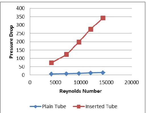
[image:5.595.309.557.446.640.2]© 2016, IRJET ISO 9001:2008 Certified Journal Page 479 Fig. 6.4 Pressure Drop vs Reynolds Number
From the Fig.6.4 it is observed that as Reynolds increases there is an increase in pressure drop is observed. This is because pressure drop is directly proportional to the velocity. So as velocity increases (i.e. Reynolds number increases) pressure drop will increase. From fig.6.4, it is observed that least pressure drop is obtained in smooth tube without using any inserts. In Rotor inserts it give maximum pressure drop because pressure drop is maximum in tube.
7. CONCLUSIONS
Analytical study has been done to get the experimental and Numerical values verified. By using Rotor inserted tube we get highly turbulent flow compare to plain tube. Double pipe type of counter flow heat exchanger was employed. Reynolds number range for fully develop flow is from Re 3000 to 1.26 ×10⁶ covering turbulent range.
Overall heat transfer coefficient of Rotor inserted tube heat exchanger increases compare to plain tube.
8. ACKNOWLEDGEMENT
Special thanks to Dr. M. Basavaraj, Dept. of Mechanical Engg. Ballarpur Institute of Technology, for providing Technical Support for completing the study.
8. NOMENCLATURE
A = Cross sectional area of inner pipe (m2)
Cp = Specific Heat capacity of the fluid , (J/KgK) di = Inner diameter of inner pipe, (m)
Di = Inner diameter of outer pipe, (m) do = Outer diameter of inner pipe, (m) Do = Outer diameter of Outer pipe, (m)
hi = Convective heat-transfer coefficient of fluid in inner pipe, (W/m2 K)
ho = Convective heat-transfer coefficient of fluid in outer pipe, (W/m2 K)
k = Thermal conductivity of inner pipe material, (W/mK) L = Total pipe length, (m)
m = Mass flow rate of water , (kg/s) Nu = Nusselt number of fluid Pr = Prandtl number of fluid Re = Reynolds number of fluid
Thi = Inlet temperature of hot water, (oC)
Tho = Outlet temperature of hot water, (oC)
Tci = Inlet temperature of cold water, (oC)
Tco = Outlet temperature of cold water, (oC)
V = Velocity of the fluid , (m/s) Q = Heat transfer rate, (m3 /s)
U = Overall heat-transfer coefficient, (W/m2 K)
9. REFERENCES
[1] Z.Y. Guo a, W.Q. Tao b, R.K. Shah,” The field synergy (coordination) principle and its applications in enhancing single phase convective heat transfer”, 26 January 2005, International Journal of Heat and Mass Transfer 48 [2005] 1797–1807
[2] Xiang-hui Tan, Dong-sheng Zhu, Guo-yan Zhou, Li-ding Zeng, “Heat transfer and pressure drop performance of twisted oval tube heat exchanger”, 29 June 2012, Applied Thermal Engineering 50 [2013] 374e383
[3] Xiang-hui Tan, Dong-sheng Zhu, Guo-yan Zhou, Li-ding Zeng,” Experimental and numerical study of convective heat transfer and fluid flow in twisted oval tubes”, 14 May 2012, International Journal of Heat and Mass Transfer 55 [2012] 4701–4710
[4] Sheng Yang, Li Zhang, Hong Xu,” Experimental study on convective heat transfer and flow resistance
characteristics of water flow in twisted elliptical tubes”, 30 May 2011 , Applied Thermal Engineering 31 [2011]
© 2016, IRJET ISO 9001:2008 Certified Journal Page 480 August 2011, International Communications in Heat and
Mass Transfer 38 [2011] 1384–1391
[6] Luai M. Al-Hadhrami,” Experimental Study Of Fouling Resistance in Twisted Tube Heat Exchanger”, 11 Apr 2012, Heat Transfer Engineering, 33[12]:1024–1032, 2012
[7] TEMA, 1988 Standards of the Tubular Exchanger Manufacturers‟ Association, New York 7th ed.
[8] Butterworth, D., Guy, A. R., and Welkey, J. J., Design and Application of Twisted Tube Heat Exchangers.
[9] Donald Q. Kern. 1965, Process Heat Transfer [23rd Printing 1986]. McGraw -Hill Companies. ISBN 0-07-Y85353-3.
[10] Comparison and maximal Velocity ratio of shell and Tube heat exchanger with Continuous Helical Baffle, ASME journal, pp. 1-8.
[11] Andre L. H Costa, M. Queiroz, [2008], Design Optimization of shell And Tube heat exchanger, Applied Thermal Engineering,vol.28. pp. 1798- 1805
[12] R.K.Rajput, “Heat and Mass Transfer books”,7th
Edition: 2007-2008, Page No. 574-577, 607 [Example 10.28] & Page No. 619-622.
[13] C.P. Kothandaraman, S.Subramanyan,”Heat and Mass Transfer Data Book”, 6thEdition:2007, Page