© 2016, IRJET | Impact Factor value: 4.45 | ISO 9001:2008 Certified Journal | Page 988
Mitigation of Voltage Sags & Swells in LV Distribution System
Using Dynamic Voltage Restorer
Anil kumar 1, Shri Bhagwan 2, J. S. Soni 3
12M. Tech Scholar, Power Systems, SGI, Sikar, Rajasthan, INDIA 3Assistant Professor, EE Department, BKBIET, Pilani, Rajasthan, INDIA
Abstract: In recent years, Power quality is one of the major concerns in modern power system.It has
become important especially with the introduction of new advance devices, which are very sensitive to the power quality and their performance is dependent of quality of power. In modern industries, electronic controllers to control load equipment which are highly sensitive to poor voltage quality and will shut down if the supply voltage is low and may mal-function in other ways if harmonic content of the supply voltage is high. In this paper work among the different custom power devices, Dynamic Voltage Restorer (DVR) has been used to improve the quality of power under different conditions.Keywords: Power quality, DVR, Sag & swell, Voltage disturbances
1.
INTRODUCTION
Power quality problems is an occurrence manifested as nonstandard voltage, current or frequency, the result in failure or miss operation of end user equipment. Much of this modern load equipment itself uses electronic switching devices which themselves could be responsible or lead to poor voltage quality in network. The introduction of competition into power sector has created larger business awareness of the problems of power quality whereas instrumentality is has become possible to measure current and standard of the voltage wave so quantify the problem.
With a rapid change in technology in industrial
control process, electric utilities are
experiencing more demanding requirements on the power quality from the large industrial power consumers and the organization of the worldwide economy has evolved towards globalization and the profit margins of many
activities tend to decrease. The increased sensitivity of the vast majority of processes like (industrial, services and even residential) to power quality problems turns the availability of electric power with quality a necessary factor for every activity sector. The information technology services and the continuous process industry are most critical area. Due to disturbance, in power supply or poor power quality may result in huge amount of economic losses, with the consequent loss of productivity and affordability.
2.
DYNAMIC Voltage RESTORER:
© 2016, IRJET | Impact Factor value: 4.45 | ISO 9001:2008 Certified Journal | Page 989 through breaker trips. Modern pulse-width
modulated (PWM) inverters capable of generating accurate high quality voltage waveforms form the power electronic heart of the new Custom Power devices like DVR. Because the performance of the overall control system largely depends on the quality of the applied control strategy, a highperformance controller with fast transient response and good steady state characteristics is required. The main considerations for the control system of a DVR include: sag detection, voltage reference generation and transient and steady-state control of the injected voltage.
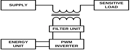
SUPPLY SENSITIVE
LOAD
PWM INVERTER ENERGY
UNIT
[image:2.612.37.287.336.433.2]FILTER UNIT
Figure 1 Typical application of DVR and its output.
Futures of DVR
Lower cost, smaller size, and its fast dynamic
response to the disturbance.
Ability to control active power flow.
Higher energy capacity and lower costs
compared to the SMES device.
Less maintenance required. UPS is costly; it also requires a high level of maintenance because batteries leak and have to be replaced as often as every five years.
LOCATION OF DVR
DVR is connected in the utility primary distribution feeder. This location of DVR mitigates the certain group of customer by faults on the adjacent feeder as shown in Figure2.The
point of common coupling (PCC) feds the load and the fault. The voltage sag in the system is calculated by using voltage divider rule. [1]
Vs Zs
Zf
DVR
LOAD-1
LOAD-3
LOAD-3
[image:2.612.327.571.353.478.2]DISTRIBUTION LINE TRANSMISSION LINE
Figure 2 Location of DVR
3. WORKING OF DVR
Among the voltage transients (sags, swells, harmonics…), the voltage sags are the most severe disturbance. The users may improve end-use devices or end-use protection devices to reduce
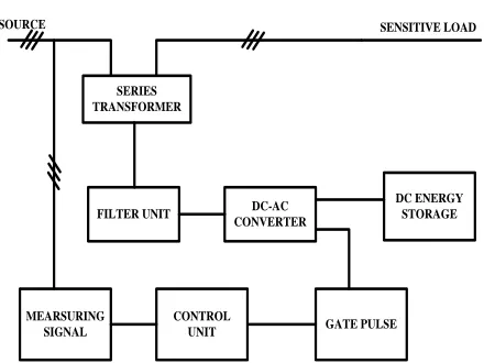
© 2016, IRJET | Impact Factor value: 4.45 | ISO 9001:2008 Certified Journal | Page 990 SERIES
TRANSFORMER
FILTER UNIT DC-AC CONVERTER
GATE PULSE CONTROL
UNIT MEARSURING
SIGNAL
DC ENERGY STORAGE
[image:3.612.52.272.99.264.2]SOURCE SENSITIVE LOAD
Figure 3Function blocks of designed DVR It is a solid state DC to AC switching power electronic converter that injects threesingle-phase AC voltages in series between the feeder and sensitive load. Using a DVR is more reliable and quick solution to maintain with a clean supply of electricity for customers. But standby losses, equipment costs and required large investigation for design are the main drawbacks of DVR. The PWM inverter unit produces required missing voltage by evaluating the control unit signals and this compensating voltage is inserted to the system by injection transformers.
4.
Simulink Model of Dynamic Voltage
Restorer
Figure 4 shows the diagram for the system under fault condition using DVR. By proper tuning of the controller required voltage to mitigate the voltage sag for few cycle is injected through series connected transformer, so that the voltage across the line remain at its nominal value even under fault condition.
Figure 4 Dynamic Voltage Restorer
Simulation of Phase Locked Loop As mentioned in block diagram of DVR. 1st step in
design of the DVR is to make the Phase Locked Loop for tracking continuously the fundamental frequency of measured system voltages. Two
[image:3.612.328.608.289.472.2]© 2016, IRJET | Impact Factor value: 4.45 | ISO 9001:2008 Certified Journal | Page 991 Figure 5 Phase Locked Loop
Figure 6 Outputs of PLL
Generation of gate pulses
Now for the generation of pulses, compensated voltage signal is compared with the triangular wave of amplitude 1pu and having the frequency
of 1.5 kHz. The generated pulses are as shown in figure7.
Figure 7 Generation of Gate pulse
5.
SIMULATION
RESULTS
FOR
CONSECUTIVE SAG AND SWELL
© 2016, IRJET | Impact Factor value: 4.45 | ISO 9001:2008 Certified Journal | Page 992 Figure 8 Load Voltages under sag and swell condition
Figure 9 Injected Voltage by DVR
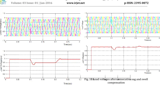
Fig. 10 Load voltages after consecutive sag and swell compensation
After the injection of the voltage by the DVR the voltage across the line remains constant such that the sensitive loads are not affected by the voltage sags or voltage swells.
6.
CONCLUTION AND FUTURE WORK
In this thesis the main objective s for the utilization of the studied equipment to mitigate the voltage sag and voltage swell. In order to protect critical loads from more sever fault in distribution network. The series connected voltage source converter known as Dynamic Voltage Restorer is more suitable and satisfactory. It is reliable, cost effective solution for compensation of voltage.
FUTURE SCOPE
It is possible to use shunt converter topology
instead of constant battery storage element.
Other methods such as phase advance
[image:5.612.38.578.389.680.2]© 2016, IRJET | Impact Factor value: 4.45 | ISO 9001:2008 Certified Journal | Page 993 Other technique for the generation of pulses may
be implemented.
REFERENCES
1. Simulation and modeling of a dynamic voltage restorer, Mehmet Tmay, Ahmet Teke, K. CagatayByindr, M. UrgasCuma, Cukurova University, Faculty of engineering and Architecture, Department of Electrical & Electronics Engineering, 01330, Balcah, Adana, Turkey.
2. Simulation of D-DSTATCOM and DVR in power system By S.V. Kumar and S.Siva Nagaraj J.N.T.U college of engineering Kakinada, A.P., India
3. Supervisory control of dynamic voltage restorers, V.K. Ramachandaramurthy, A. Arulampalam, C. Fitzer, C. Zhan, M. Barnes and N. Jenkins
4.A Detailed comparison of system topologies for Dynamic voltage restorers, John Godask Nielsen and FredeBlaabjerg, fellow, IEEE, IEEE transaction on industry application, vol, 41, No. 5september/October 2005
5. A Novel Dynamic Voltage Restorer based on Matrix Converters, José M. Lozano, Juan M. Ramirez, Member, IEEE, CINVESTAV IPN, Guadalajara Campus Av. Científica No.1145, 45015 Zapopan, México, Rosa Elvira Correa Universidad Nacional De Colombia – Medellin
6. A Dynamic Voltage Restorer (DVR) With Selective Harmonic Compensation at Medium Voltage Level, Michael John Newman, Member, IEEE, Donald Grahame Holmes, Senior Member, IEEE, John Godsk Nielsen, Member, IEEE, and FredeBlaabjerg, Fellow, IEEE, IEEE Transaction on industry application, vol. 41, no. 6, November/December 2005
7. Mitigation of Voltage Disturbances Using Adaptive Perceptron-Based Control Algorithm, Amr Elnady, Student Member, IEEE, and Magdy M. A. Salama, Fellow, IEEE, IEEE Transaction on power delivery, vol. 20, no. 1, January 2005
8. Investigation of Inter-Line Dynamic Voltage Restorer in Multi Feeder Distribution System for Voltage Sag
Mitigation, Ahmed Hossam-Eldin Ahmed Elserougi Ahmed MassoudShehab Ahmed, Proceedings of the 14th International Middle East Power Systems Conference (MEPCON’10), Cairo University, Egypt, December 19-21, 2010, Paper ID 163.
9.Interline Dynamic Voltage Restorer: A novel Approach for Multiline power quality compensation, D. MhindaVilathgamuwa, senior member IEEE, H.M. Wijekoon, Student member IEEE, S.S. Choi, member IEEE.