5815
VERIFICATION OF VHDL DESCRIPTIONS OF PARALLEL
ARRAYS OF FINITE STATE MACHINES
NIKOLAY ALEKSANDROVICH AVDEEV1, PETR NIKOLAEVICH BIBILO1, VLADIMIR
VLADIMIROVICH KOROBKIN2, AND ANNA EVGENIEVNA KOLODENKOVA3
1 United Institute of Informatics Problems, National Academy of Sciences of Belarus, ul. Surganova 6, Minsk, 220012 Belarus
2 Acad. Kalyaev Scientific Research Institute of Multiprocessor Computer Systems, ul. Chekhova 2, Taganrog, 347928 Russia
3 Ufa State Aviation Technical University (USATU), ul. K. Marksa 12, Ufa, 450008 Russia
ABSTRACT
Finite state machines are widely applied in the development of digital systems for description of control logic nodes, microprocessors, interface circuits and so on. This work proposes verification procedure of VHDL description of parallel arrays of finite state machines in Questa Sim simulation system. The main advantage of Questa Sim is that the model of finite state machine (FSM) can be verified if its written according to certain template. Verification is comprised of validating for compliance of VHDL description of finites state machine array with design specifications. The method utilizes the capabilities of the Questa Sim system, which makes it possible to identify the oriented graphs of the transitions of the component machines and to calculate the number of the arc passings in the graphs based on the results of simulation. However, the Questa Sim system does not recognize the FSM network and does not have the means to construct the tests based on the simulation results. Therefore, to solve these problems, it is suggested to store the simulation results – the sequence of input sets (stimuli) and the state tuples of the component machines, and to check the execution of transitions in the state graph of the machine network based on the sequences obtained, and, thus, to conduct the verification. In addition, this article discusses an example of description of FSM and FSM arrays using VHDL.
Key words: Digital Systems, VHDL Descriptions, Verification, Simulation, Finite State Machines.
1. INTRODUCTION
Automata-based style is widely used in programming since it allows to solve verification issues of software more successfully, including methods of formal verification [1-3]. While developing digital systems, which are implemented in hardware as logic systems, the FSM models are also widely applied, especially for description of control logic nodes, microprocessors, interface circuits and so on. Two languages occupy leading position for description of digital systems: Verilog [4-9] and VHDL [10-14]. We will discuss description examples of FSM and FSM arrays using VHDL, however, the proposed practical procedure of verification of FSM arrays can be applied also for projects written in the Verilog language.
The VHDL descriptions of FSM arrays are used for synthesis of synchronous logical circuits in this or that basis of logical elements known as engineering (target0 basis or target library of logical elements. At present the synthesis is automated, and the most important issue during development of VLSI circuits and systems-on-chips is verification [15] of initial VHDL models used for
algorithmic description of designed digital devices and systems.
Contrary to formal verification, when behavior equivalence is verified by two VHDL descriptions of digital system, this article considers verification as verification of validity of initial VHDL description, that is, validating of compliance of synthesized VHDL description of designed digital system with design specifications [15].
5816 networks. However, the Questa Sim system can not recognize the network of automatic machines and has no options to construct the functional tests based on the simulation results.
The objective of this article is the automated construction of such tests based on the results of the simulation of the VHDL-descriptions of the FSM networks. To conduct the simulation, it is required to write the test VHDL programs utilizing the options for pseudorandom test sets generation and the options for functional coverage.
2. FORMULATION OF THE PROBLEM
Initial design specifications of separate (component) FSM and arrays of interacting FSM are generally predefined in the form of spreadsheets or oriented graphs of transitions between states of component FSM, the nodes of which corresponds to states and oriented branches to transitions between the states. Then, the state of component FSM is always considered as its internal state, and the state of array of synchronous FSM is considered as a tuple of internal states of component FSM. On the basis of non-formal specifications VHDL descriptions are arranged, which are formal and simulated, and which require verification. The main approach to such verification is simulation which requires for:
- development of testing programs; - arrangement of appropriate tests or VHDL programs generating tests;
- simulation and comparison of obtained responses of VHDL model with expected responses.
Development of testing programs and simulation using Questa Sim system is described in details in [15, 16]. Subsequently, VHDL descriptions will be simulated in Questa Sim, some peculiar features of this system will be discussed.
Verification of VHDL description of separate component FSM is discussed in [17], it is comprised of verification of feasibility of all states of FSM and execution of all required transitions between the FSM states. For FSM array the problem is much more complicated, since it is required to verify that component FSM are synchronously in the required state. In addition, it is important to verify that the component FSM in the array are not simultaneously in prohibited state.
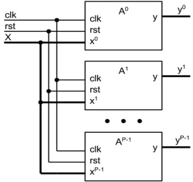
Let us introduce notations and formulate the problem. Let A0, A1,…, Ap–1 are the component FSM with common input signals of the set X and
common synchronous signal clk;
}
q
,...,
q
{
Q
0 00 k00
,Q
1{
q
10,...,
q
1k}
1
,…,
Q
p{
q
p,...,
q
kp}
p
1 1
0 1
1
are theinternal FSM states; G0, G1,…, Gp–1 are the graphs
of transitions between states of component FSM; p
– is the number of the component machines
.
Mathematical models of FSM are widely known in literature [18], VHDL descriptions of synchronous FSM are available in [4, 10, 15]. [image:2.612.96.294.510.697.2]Component FSM generates parallel array H (Fig. 1), that is, the transitions between the states of all component FSM are performed synchronously, for instance, positive edge of synchronous signal clk.
Fig. 1. General view of FSM parallel array.
Let us call generalized graph of transitions the graph GH, the nodes of which are
ordered vectors (tuples). In each tuple the i-th component is the element of the set Qi, i = 0, 1, …, p–1. It can be seen that the set Q of nodes of the graph GH forms the Cartesian product of the sets
i
Q
:Q
Q
0
Q
1
...
Q
p1. Now let us denote as Z the subset of nodes of the graph GH,which is prohibited state. The FSM array H should never be in a state included into Z. Let us call the subset
R
Q
\
Z
of array H states the set ofallowed states of the array. It should be mentioned that the allowed array states can include
5817 A transition (a branch of graph GH) is considered as prohibited, if it leads to a prohibited state. The model of component FSM and its VHDL description are considered as correct, if from any internal FSM state there is a transition to FSM initial state. The combination of initial states of component FSM will generate initial state of the array H.
Problem. VHDL description of parallel array H of FSM and subset Z of prohibited states are predefined. It is required to verify VHDL description, that is, to verify whether in the graph
GH the transitions to allowed states R are executed and the transitions to prohibited states Z are not executed.
The problem of verification of the initial high-level VHDL-descriptions (or the Verilog-descriptions) and the design specifications have been considered in a great number of scientific papers. The point at issue is about the conformity of the HDL-model of the digital device to the design specifications. Two basic approaches can be utilized for such verification. The first approach [14, 15] is formal and includes the construction of the corresponding High-Level Decision Diagram (HLLDD) model, which is compared with the conditions of the operation of the Extended Finite State Machines (EFSM) built based on the original HDL-description, as the specifications. The generation of the functional test is reduced to the construction of the counterexample in the form of a sequence of the input test sets, the use of which in the simulation results in a behavior that contradicts the specification. The above-mentioned is a concretization of the approach known in the literature as the model checking [16]. This approach is limited to the HDL-description styles, from which the corresponding models are extracted. Another approach is implemented on the basis of the simulation and complex testing, aimed at the appropriate checks for verify the correct functionality of the HDL-description [11]. This approach is not limited to the styles of the source descriptions, the main problems are the generation of the directed functional tests and the arrangement of the testing. In the framework of this approach, it is proposed to solve the task of verification of parallel array of the FSMs.
Since it is assumed that the verification problem will be solved on the basis of simulation in
Questa Sim, then the question is not the strict solution of the problem, that is, strict (formal) verification of VHDL model. If it is found that there are transitions to prohibited states, then it will evidence incorrect VHDL description of FSM
array; if after all kinds of simulations (the set of tests is always limited) it is found that all allowed transitions are executed (covered) upon simulation and there is no transition to prohibited state, then it is conditionally considered that the VHDL description of the array H is correct.
3. VERIFICATION PROCEDURE OF VHDL DESCRIPTIONS OF ARRAYS OF FINITE STATE MACHINES
In verification of the network of H
machines it is required to verify each of
A
0,A
1, …,A
p1machines of the network and the network of H machines as a whole. A great advantage of Questa Sim is that the FSM model can be verified if it written according to predefined template. The FSM model should have finite number of internal states, variables of current and next states should exist, state transition should be executed according to synchronous signal, next state should depend on current state. VHDL code coverage tools on the basis of compilation and simulation make it possible to recognize FSM in the model of digital system, to follow (to consider for) all covered (in actual simulation run) states of FSM, to consider for number of transitions of oriented branches in transition graph of FSM and to visualize the graph. This procedure is described in [17]. However, FSM can be written in another form, which also requires verification. Extraction of FSMA
i from VHDL description and plotting of transition graph Gi is a non-trivial problem, since it is reduced to analysis of VHDL code, the syntax of which is complex, and FSM can be defined in another form (style), differing from the required form of description, and in such case Questa Simwill not be able to recognize it. In fact, the development of mathematical model of transition graph should be automated according to VHDL program defining FSM, for instance, to develop vertex incidence matrix of oriented transition graph. The problem becomes more complicated for FSM array, since it is required to plot graph
G
H on the basis of preset VHDL description of array H.5818 which the FSM will be at the next simulation run. For component FSM such approach is described in [17]. This approach [17] is easily generalized for the case of parallel array of FSM: during simulation it is required at each run to provide the state of each component FSM, then the vertex set of graph GH will be formed by all various tuples of internal states of component FSM. Covering all transitions in such graph will be reduced to searching of adjacent pairs in the state sequence of the array H. This approach can be readily implemented, however, its disadvantages are also obvious regarding supply of pseudo-random input impacts and absence of guaranteed covering of each transition in the graph GH. Pseudorandom tests should be long and even in this case it is difficult to cover all transitions, especially this relates to covering of all transitions to initial state caused by reset. Therefore, the important role is played by correct development of testing programs which provide generation of input impacts and verify achievement of certain purposes of verification. It is proposed to use the options of VHDL-packages implementing OS-VVM (Open Source VHDL Verification Methodology) to write the test VHDL-programs [10].
The proposed verification procedure of VHDL-descriptions of FSM arrays using Questa Sim
is comprised of the following stages.
Stage 1. Informal verification of the required style for the description of the component machines, namely, the style enabling the Questa Sim system to select each component machine. A formal verification of the correctness of the style used is carried out in Stage 3.
Stage 2. Simulation of the VHDL-description of the network of machines using specially written testing programs allowing to generate pseudorandom input effects, to submit them to the input of the VHDL model and to obtain the states of the network of the machines at each stroke. Thus, the results of the stroke simulation are the input effects for a network of machines and the corresponding tuples of states of the component machines.
Stage 3. Visualization of the component
machines transition graphs and the verification of the execution of all required transitions of the component machines according to the original specifications. If the FSM model is not extracted from the VHDL-description, i.e. if the graph of the component automaton is not visualized, then it is required to return to the Stage 1, and to bring the
VHDL description of the component machine to the required form.
Stage 4. Plotting of the graph GH
according to simulation results.
Stage 5. Analysis of the graph GH, that is,
- obtaining of list of accessible and inaccessible array states;
- verification of occurrence of prohibited states by the array.
Stage 6. Development of compact test for the functional verification of the array, that is, the verification of the execution of all transitions in the graph GH.
Stage 7.Correction of VHDL
descriptions, when the design specifications are not met.
The general mathematical (combinatorial) problem is the problem of construction of the test in Stage 6. This problem is associated with the problem of circumvention of the oriented graph
H
G
to cover all the arcs. This problem can be worded as follows: for a given oriented graph, to find the shortest cycle, containing all the arcs of the graphG
H. This problem is a well-known case of the Chinese postman problem for the oriented graphs [17, 18]. At stage 2, this problem arises for the graphsG
0,G
1,…,G
p1 , transitions of the component machines, but the number of vertices of the graphG
His much larger than the number of vertices of each of the component machines and it can reach the product of the number of vertices of the graphs of the component machines.4. RESULTS
Component FSM (node) can exist in one of the three states: I (Invalid), S (Shared), M
(Modified). All component FSM parallel array H
comprised of p receives input signals, such as: <op,
5819 As mentioned in [15], the considered model of the FSM array H is the generalized description of MSI protocol [20], which provides coherence of distributed memory, and the verification that two nodes cannot be simultaneously in the state M is the task of
[image:5.612.204.408.370.519.2]verification of this protocol. In order to write VHDL code describing node behavior, let us present it in Table 1. In fact, these are initial specifications for design and hardware of the FSM array.
Table 1. Description of behavior of FSM array
Node i (i=0,1,2,…,
p-1)
Input impacts
<R, j> <W, j> <E, j>
i=j
I → SS → S M → M
M, S, I → M M, S, I → I
i ≠ j M → S S → S I → I
M, S, I → I S → S M → M
I → I
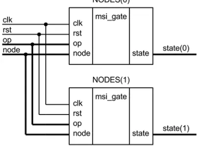
Let us consider VHDL description (listing 1) of parallel array (Fig. 2) of two (p = 2) component FSM, then the set Z of prohibited states
will include the only vertex of the graph
G
H, marked as <M, M>.Fig. 2. Parallel Array Of Two Nodes NODES(0), NODES(1).
Stage 1. The VHDL description of the
msi_gate component machine meets the requirements of the Questa Sim system, which can extract the final state machine, find its internal states, and analyze the performed transitions on the internal state graph, as will be shown in Stage 3.
Stage 2. Let us simulate the network of
machines with 10 000 pseudorandom input sets of the form <op, j> using the testing program
The testing program generates pseudorandom test sets such as <op, 0> , <op, 1> and functional covering, it is written using the VHDL packages RandomPkg, CoveragePkg, located in the VHDL library (Library OS-VVM).
Random values of input signals op and
node are generated by variables RndOp, RndNode
such as RandomPType. The RandInt(min, max) method returns random value (type integer) from [min, max] range. In order to transform the values of integer type into operation_type the following expression is applied :
op <=
operation_type'val(integer(RndOp.R andInt(0, 2)));
Testing program collects covering of states of separate nodes 0 and 1 as well as cross states of the two nodes. This is based on variables
CovStateNode0, CovStateNode1 and
CovStateAllNodes , respectively. The model covering is preset by AddBins and AddCross
5820 input impacts (signals op, node) and FSM states (signals state(0), state(1)) are stored in the text file
all_vectors.tst.
The text file all_vectors.tst for the initial 22 strokes has the following form:
e 1 i i e 0 i i r 0 s i e 0 i i e 1 i i w 1 i m e 0 i m w 0 m i e 1 m i e 1 m i w 0 m i e 1 m i w 0 m i w 1 i m r 1 i m e 1 i i w 1 i m r 0 s s e 0 i s e 1 i i
Before termination of the testing program the results of covering are printed into console by
WriteBin method, where all states of separate nodes were covered several times (the values Count are above zero). For cross covering of the two nodes the states can be seen which have not been covered (Count=0). These are the states 1-2 (<S, M>), 2-1 (<M, S>) and 2-2 (<M, M>), which are inaccessible in this test.
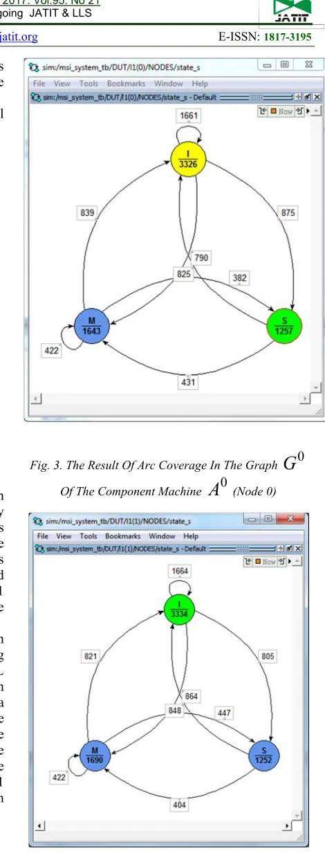
Stage 3. Having completed the simulation
[image:6.612.306.537.41.361.2]of the network of machines using the testing program (Listing 2), one can verify that the VHDL models of the component machines are written in accordance with the requirements of the Questa Sim simulation system, based on these graphs the transition graphs are extracted, visualized to be compared with the source graphs, which are the design specifications for the VHDL code. The results of verification of the node 0 and the node 1 in the Questa Sim simulation system are shown in Fig. 3 and 4, respectively.
[image:6.612.296.531.52.675.2]Fig. 3. The Result Of Arc Coverage In The Graph
G
0Of The Component Machine
A
0 (Node 0)Fig. 4. The Result Of Arc Coverage In The Graph
G
1 [image:6.612.314.521.389.672.2]5821
Stage 4. The results of the simulation on
the initial strokes are given in Table. 2, where the input influences are given in the second column, while the tuples of the states of component machines are given in the third column. Most often the network was in a state <M, I>. In the right part of the Table. 2 the passable cycles on the subgraph of the oriented graph
G
Hare shown. Let us consider the runs 7 and 8 in Table 2: in the array state <I, M> the input receives <W, 0>, then the array transits to the state <M, I>. From the data of two lines of respective test files obtained by simulation the branch of the graph GH is "extracted"originating from the vertex <I, M> and entering into the vertex <M, I> .
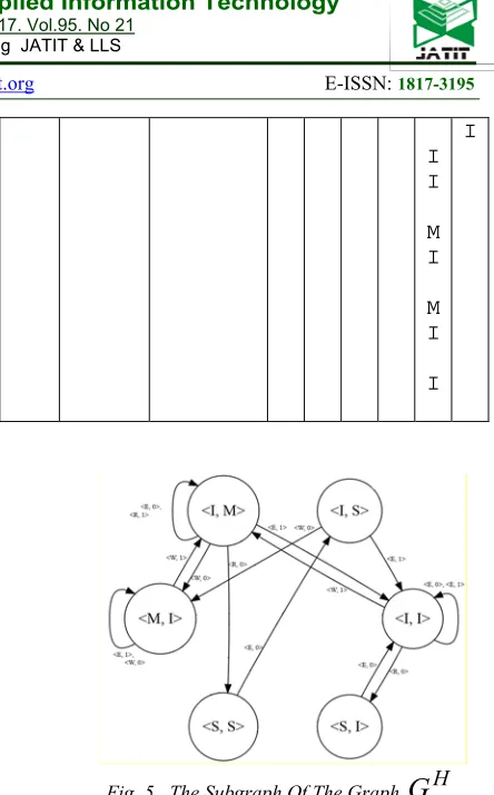
[image:7.612.308.530.41.398.2] [image:7.612.89.317.314.730.2]The subgraph of the oriented graph
G
H obtained at the initial 22 strokes is shown in the Fig. 5.Table 2. Simulation Results Of FSM Array
Ru n Input impact s (test)) The states of the componen t machines
Cycles in graph
H
G
1 2 3 4 5 6
0 1 2 3 4 5 6 7 8 9 10 11 12 13 14 15 16 17 18 19 20 21 E 1 E 0 R 0 E 0 E 1 W 1 E 0 W 0 E 1 E 1 W 0 E 1 W 0 W 1 R 1 E 1 W 1 R 0 E 0 E 1 W 0 I I I I I I S I I I I I I M I M M I M I M I M I M I M I I M I M I I I M S S I S I I M I I I I I I I I I I I S I I I I I I I I I I M I M M I M I M I M I M I M I I I M S S I S I I I M I M I I I
Fig. 5. The Subgraph Of The Graph
G
H, Obtained Based On The Results Of The Simulation Of The Machine Network At 21 Input Impact From Table 2It is premature to draw conclusions about the correctness or incorrectness of the VHDL-description based on the results of simulation at two dozen strokes, therefore the network simulation for 10 000 pseudorandom input impacts was performed; Fig. 6 shows the graph obtained from the results of this simulation.
5822
Stage 5. The analysis of the
G
H graph.A list of completed transitions and the lists of achievable and unattainable states can easily be obtained from the graph
G
H. The list of achievable network states: <I, I>, <S, I>, <I, M>, <M, I>, <S, S>, <I, S> includes the non-isolated vertices ofG
H. The list of unattainable states of the network: <M, S>, <S, M>, <M, M> includes the tuples of states of component machines excluded from the third column of the Table. 2. The basic requirement for the states of the network of machines is fulfilled – the network has never entered the forbidden state <M, M> in this simulation session.The lines in bold in the Listing 3, in fact, inform the designer of the vertices <M, S>, <S, M>, <M, M> that do not fall into the graph
G
H.Stage 6. Construction of the compact tests
for the verification of the network of machines. The result of processing of the input impact files and the corresponding tuples of states of the component machines enables the construction of the graph
H
G
. To automate the construction of the graph HG
and to obtain a compact functional test that provides the coverage of all the arcs of this graph, the CoverGraph software was modified [12]. The input test sets corresponding to the arcs included in the graph coverage will form a test for the functional verification of the network of machines.In the example under consideration, the CoverGraph software based on the simulation of the network of machines constructs a compact test of 50 input impacts to cover 28 arcs of the graph shown in Fig. 6. Note that in this case we are talking about coverage of six vertices of a given graph (interconnected by the arcs). As a result of the simulation, none of the three isolated vertices <S, M>, <M, S>, <M, M> was obtained. This graph (Figure 6) corresponds to the case NUMBER_OF_NODES = 2 of the two-node network of machines.
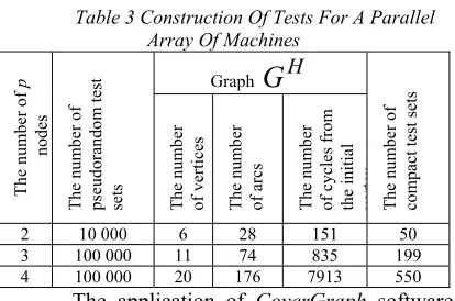
[image:8.612.316.523.91.228.2]The results of experiments for the network of machines with a larger number (3, 4) of component machines are given in Table. 3. The simulation of all networks was carried out for 10 000 or 100 000 pseudorandom input sets of the form <op, j>.
Table 3 Construction Of Tests For A Parallel Array Of Machines
T he num ber of p nodes T he num ber of pseudor and om test sets
Graph
G
HT
he
num
ber
of
compact test se
ts
T
he
num
ber
of vertices The
num ber of a rc s T he num ber of c ycles fr om
the initial ver
tex
2 10 000 6 28 151 50
3 100 000 11 74 835 199
4 100 000 20 176 7913 550
The application of CoverGraph software makes it possible to reduce significantly the verification tests, for example, instead of the one hundred thousand input sets for the case p = 3, 199 sets of the constructed compact test can be utilized.
Stage 7. In this example, the proposed verification method for VHDL-descriptions of the FSM network has revealed no errors, the correction of the initial description is not required.
Other computational experiments were carried out based on the examples of VHDL descriptions of the FSM networks using
CoverGraph software. The experiments have shown that in order to maximize the coverage of the
H
G
graph arcs, one should perform the simulation on as many random input impacts as possible.Having constructed the compact tests to verify the transitions among the states, it is possible to simulate the correspondence of the output signals of the FSM network to the required values, and thereby to perform another aspect of the functional verification on the basis of modeling – not merely the check of the required transitions but also the required responds of the component machines.
The significant computational problem is the construction of the compact tests, the finding of which is associated with the circumvention of the high-dimensioned oriented graphs.
5. CONCLUSION
Compliance with simple rules of description of FSM makes it possible to perform functional covering and visualization of transition graphs of component FSM in Questa Sim. Simulation can be applied for rapid verification of FSM array, to reveal assumed prohibited and inaccessible parallel states and non-covered transitions between FSM array states. CoverGraph
5823 are directional and can be used for the functional verification and testing of the entire projected digital system, according to the methodology presented in [11]. The proposed verification procedure of VHDL descriptions of parallel array of FSM can be easily generalized for the case of interacting FSM, upon each simulation run it is required to retain input impacts, states, and output responses of both overall array and of component FSM. Formal verification of VHDL descriptions of FSM array and validation of project properties (for instance, validation of statement that system is in prohibited state) require for other simulation systems, for instance, Questa PropCheck, making it possible to perform formal verification of properties of project written in VHDL.
ACKNOWLEDGMENTS
This work was supported by the Russian Foundation for Basic Research, grants No. 16-58-00191 Bel_а, No. 17-08-00402
REFERENCES
[1] Shalyto A.A. Paradigma avtomatnogo programmirovaniya [Automata-based programming paradigm]. Scientific and technical bulletin of St. Petersburg state university of IT, mechanics and optics. Issue 53. Automata-based programmingб 2008, pp. 137-144.
[2] Kuz`min E.V. and Sokolov V.A. Modelirovanie, spetsifikatsiya i verifikatsiya “avtomatnykh” programm [Simulation, specification and verification of automata-based programs]. Programmirovanie, 2008, No. 1, pp. 38-60.
[3] Vel`der S. E., Lukin M. A., Shalyto A. A., and Yaminov B. R. Verifikatsiya avtomatnykh programm [Verification of automata-based programs]. Nauka, St. Petersburg, 2011. [4] Polyakov A. K. Yazyki VHDL i VERILOG v
proektirovanii tsifrovoi apparatury [The VHDL and VERILOG languages in designing of digital hardware]. SOLON-Press, Moscow, 2003.
[5] Khakhanov V.I., Khakhanova I.V., Litvinova E.I., and Guz` O.A. Proektirovanie i verifikatsiya tsifrovykh sistem na kristallakh [Designing and verification of digital systems-on-chip] . Verilog & SystemVerilog. KhNURE, Kharkov, 2010.
[6] Spear C., Tumbush G. System Verilog for Verification. A Guide to Learning the Testbench Language Features, Springer, 2012. [7] Ashenden P. J., Lewis J. VHDL-2008. Just the
New Stuff. – Burlington, MA, USA. Morgan Kaufman Publishers, 2008. Solov`ev V. V. [8] E. A. Suvorova and Yu. E. Sheinin.
Proektirovanie tsifrovykh sistem na VHDL [Designing of digital systems using VHDL] - BHV-Peterburg, St. Petersburg, 2003.
[9] Perel`roizen E.Z. Proektiruem na VHDL [VHDL programming] – SOLON-Press, Moscow, 2004
[10] Bibilo P.N. and Avdeev N.A. Modelirovanie i verifikatsiya tsifrovykh sistem na yazyke VHDL [Simulation and verification of digital systems using VHDL]. LENAND, Moscow, 2017.
[11] Chen M., Qin K., Ku H.-M., Mishra P. Validation at the system level. High-level simulation and testing management. M.: Tekhnosfera, 2014. 296 p.
[12] Bibilo P.N. and Romanov V.I. Postroenie kompaktnykh testov dlya funktsional`noi verifikatsii VHDL-opisanii konechnykh avtomatov [Development of compact tests for functional verification of VHDL descriptions of final state machines]. Upravlyayushchie sistemy i mashiny. – 2017, No. 1, pp. 35-45. [13] Zakrevskii A.D., Pottosin Yu.V., and
Cheremisinova L.D. Logicheskie osnovy proektirovaniya diskretnykh ustroistv [Logical foundations of designing of discrete hardware]. Fizmatlit, Moscow, 2007.
[14] 14.Smolov S.A. Obzor metodov izvlecheniya modeley iz HDL-opisaniy [Overview of methods for extracting models from HDL-descriptions] Trudy ISP RAN, 2015, Vol. 27, No. 1. P. 97-123.
[15] 15.Lebedev M.S., Smolov S.A. Metod generatsii funktsional'nykh testov dlya HDL-opisaniy na osnove proverki HLDD-modeley [Method for generating functional tests for HDL-descriptions based on testing of HLDD models] // Problemy razrabotki perspektivnykh mikro- i nanoelektronnykh sistem: sb. trudov pod obshch. red. akad. RAN A.L. Stempkovskogo. – M.: IPPM RAN, 2016. Part 2. P. 24-31.
5824 [17] 17. Thimbleby H. The directed Chinese
Postman Problem / Software Practice and Experience. 2003. V. 33 (11). P. 1081-1096. [18] 18. Burdonov I.B., Kosachev A.S., Kulyamin
V.V. Neizbytochnyye algoritmy obkhoda oriyentirovannykh grafov. Determinirovannyy sluchay [Inexhaustible algorithms for traversing oriented graphs. Deterministic case]// Programmirovaniye. 2003. No. 5. P. 11-30.
[19] 19. Kamkin A.S. Proetsirovanie sistem perehodov: preodolenie kombinatornogo vzryva pri verifikatsii parallel`nykh sistem [Designing of transition systems: overcoming of combinatorial explosion upon verification of parallel arrays]. Programmirovanie. 2015, No. 6, pp. 53-71.