Bending Analysis of Functionally Graded Beam
by Refined Theory
T.K.Meghare1, P.D.Jadhao2
1
Department of Civil Engineering, 2 Prof &Head of Civil Engineering Dept
K.K. Wagh Institute of Engineering Education and Research, Nasik-422003 (University of Pune), Maharashtra, India.
Abstract—A refined theory is applied for the flexural analysis of functionally graded beams. The present study involves four unknown variables which are five in first order shear deformation theory or any other higher order theories. The in-plane displacement field uses sinusoidal function in terms of thickness co-ordinate to include the shear deformation effect. The present study satisfies the zero shear stress condition at top and bottom surfaces of plates without using shear deformation factor. Variationally consistent governing equations and boundary conditions associated with present study are obtained using the virtual work principle. A closed form solution is obtained using double trigonometric series suggested by Navier. The functionally graded beam is analyzed for uniformly distributed load and linearly varying load under simply supported condition. The results are obtained and presented graphically.
Keywords— Four variables, functionally graded beams, refined theory, shear correction factor, shear deformation.
I. INTRODUCTION
The classical engineering theory of bending due to Bernoulli and Euler dates back to1705 and had its origin in the first mathematical model of nature of the resistance of a beam developed by Galileo Galilei in 1638.The classical theory of plate bending had its origin in the pioneering work of Sophie Germain carried out in 1815. The theory reached maturity due to the well-known Kirchhoff hypothesis and the resolution of famous boundary conditions paradox by Kirchhoff in 1850.
The beam and plate theories are the active areas of research since the historical time. Thick beams and plates, either isotropic or an isotropic, basically form two-and three dimensional problems of elasticity theory. Reduction of these problems to the corresponding one- and two-dimensional approximate problems for their analysis has always been the main objective of research workers. The shear deformations in beams and plates with the three dimensional nature of these problems further intensified the research interest in their accurate analysis. As a result, numerous refined theories of beams and plates have been formulated in last two decades which approximate the three dimensional solutions with reasonable accuracy. A new class of composite materials called functionally graded materials (FGMs), is considered in this paper. The potential uses of FGMs in engineering applications include aerospace structures, engine combustion chambers, fusion energy devices, engine parts and other engineering structures. In recent years, the static and dynamic analyses of functionally graded (FG) beams have increasingly attracted many researchers.
Meghare T.K. and Jadhao P.D.[1] introduced a new higher order shear deformation theory based on the elementary theory of beams. The transverse shear stress can be obtained directly from the constitutive relations satisfying the shear stress free surface conditions on the top and bottom surfaces of the beam, hence the theory does not require shear correction factor. Governing equations and boundary conditions of the theory are obtained using the principle of virtual work. The simply supported thick
isotropic beams are considered for the detailed numerical studies. Shimpi R.P. et al. [2] introduced two new displacement based
first-order shear deformation theories involving only two unknown functions, as against three functions in case of Reissner’s
and Mindlin’s theories.Ghugal Y.M. and Dahake A.G.[3] developed a trigonometric shear deformation theory for flexure of
thick or deep beams, taking into account transverse shear deformation effects. The sinusoidal function was used in displacement
field in terms of thickness coordinate represent the shear deformation effects.Sayyad A.S. and Ghugal Y.M.[4] put forward a new hyperbolic shear deformation theory developed for the static flexure of thick isotropic beam, considering hyperbolic
functions in terms of thickness co-ordinate associated with transverse shear deformation effect. Mantari J.L.et al.[5] developed a
new trigonometric shear deformation theory for isotropic and composite laminated and sandwich plates. The theory accounts for adequate distribution of the transverse shear strains through the plate thickness and tangential stress-free boundary conditions on
the plate boundary surface, thus a shear correction factor was not required.Wattanasakulpong and Ungbhakorn[6] investigate
presented a refined shear deformation theory for the static flexure and free vibration analysis of thick isotropic beams, considering sinusoidal hyperbolic and exponential function in terms of thickness co-ordinate associate with transverse shear deformation effect.
II. FUNCTIONALLY GRADED BEAM
Functionally graded materials are advanced composite materials in which the mechanical properties such as Young’s modulus of elasticity, Poisson’s ratio, shear modulus of elasticity, material density, etc. vary smoothly and continuously in preferred directions. FGMs, which consist of metallic and ceramic components, are well known to improve the properties of thermal-barrier systems, because cracking or delamination, which is often observed in conventional multilayer systems, is avoided because of the smooth transition between the properties of the components. By spatially varying the percentage contents of volume fractions of two or more materials, FGMs can be formed that will have the desired property gradation in spatial directions. Because material properties vary in the preferred directions in functionally graded (FG) structures, the stress variation is continuous; whereas in another type of advanced materials, i.e., laminated composites, the stress distribution is discontinuous. Delamination has been a problem of significant concern in the design and analysis of advanced fibre reinforced composite laminates. In laminated composites, the separation of layers caused by high local inter laminar stresses result in destruction of the load transfer mechanism, reduction of stiffness, and the loss of structural integrity, leading to final structural and functional failure. FGMs are gaining importance because of a continuous variation of volume fraction through the thickness, which can eliminate these problems. FG materials are the latest advanced materials to be discovered by material scientists for use in innovative engineering applications. Although FGMs are highly heterogeneous, it is very useful to idealize them as continua with their mechanical properties changing smoothly with respect to the spatial coordinates. Closed-form solutions of some fundamental solid mechanics problems can be obtained by this idealization and it helps in evolving and developing the numerical models of the structures made of FGMs. The material properties are generally assumed to follow gradation through the thickness in a continuous manner.
Fig.2. Geometry of functionally graded beam. For the power law distribution, the Young’s modulus is given as :
( ) ( )(0.5 )n
m c m
z
E z E E E
h
(1)
Where n is the power law index; and the subscripts m and c represent the metallic and ceramic constituents. The FG beam
becomes a fully ceramic beam when n is set to zero and it is infinity for the metallic layer.
Various research indicated that the effect of Poisson’s ratio on the behaviour of the FG beam is much less than that of the Young’s modulus, thus the Poisson’s ratio will assume to be constant in our study.
III. THE FG BEAM BENDING ANALYSIS
Consider a beam of sides ‘L’ and ‘b’ and total thickness h, composed of functionally graded material through the thickness.
Beam is subjected to various boundary and loading conditions. The beam occupies the region
0
x
L
,
h
2
z
h
2
inCartesian coordinate system. A transverse load q(x) is applied on the upper surface of the beam (i.e. z =
h
2
). Certainassumptions were made during analysis. The displacements are small in comparison with the plate thickness and therefore strains involved are infinitesimal. The beam is subjected to transverse load only and the body forces are neglected. Based on above mentioned assumptions the following displacement field associated with present theory is obtained.
( ) ( )
( ) 0( ) dw xb ( )dw xs u x u x z f z
dx dx
(2)
( ) b( ) s( )
The non- zero strains for beam are as follows
2 2
0
2 ( ) 2
b s
x
du d w d w
du
z f z
dx dx dx dx
(4)
0
( ) ( )
( ) b ( ) s ( ) ( )
zx b s
dw x dw x
du dw d d
u x z f z w x w x
dz dx dz dx dx dx
2
2 4
1 . s
zx x dw z d h (5)
The corresponding in-plane and normal stresses are as follows.
2 2
0
2 2
( ). ( ). b ( ) s
x x
du d w d w
E z E z z f z
dx dx dx
(6) ( ) ( ). . 2(1 )
xz zx zx
E z G z
(7)
The variationally consistent governing equation of equilibrium and boundary conditions associated with the present theory can be derived using the principle of virtual work. The analytical form of principle of virtual work can be written as:
/ 2
0 0 / 2
( ) . . .
L L h
x x zx zx
h
q x dx dx dz
(8)Separating above equation and by further calculation, final governing differential equations are obtained.
2 3 3
0
0 2 0 4 0 3 0
b s
u w w
A B C
x x x
(9a) 4 0
0 0 0 4
4 3 3 4 s b u w E x w
B D q
x x (9b)
0 4 4 2
0 0 4 0 4 0 0 2
3
3
b s s
u w w w
E F A q
x x x
C x (9c)
The constants appeared in the above governing equations and associate boundary conditions are as follows:
/ 2 0 / 2 . h h
A E dz
/2 0 / 2 . . h hB E z dz
/ 2 0 / 2 . ( ). h hC E f z dz
/ 2 2 0 / 2 . . h hD E z dz
/ 2 0 / 2 . . ( ). h hE E z f z d z
/ 2 2 0 / 2 . ( ). h hF E f z dz
(10)
/ 2
2 00
/ 2
.(1 '( )) .
h
h
A G f z dz
IV. ILLUSTRATIVE EXAMPLES
A simply supported isotropic beam occupying the region given by the Eq. (1) is considered. The beam is subjected to uniformly
distributed transverse load, q(x) on surface z = −h/2 acting in the downward z-direction as given below:
1 , 3 , 5
( ) ms in
m
m x
q x q
L
(11)Uniformly distributed load
0 2 4 m q q m
For
m
1, 3, 5,...,
(12)
The following solution form is assumed for unknown displacement variable
w
b,
w
ssatisfying the boundary conditions for©IJRASET 2015: All Rights are Reserved
87
sin sin bm b s sm m x w w Lw m x
w L (13)
Where
w
bm and wsm are arbitrary constants, which can be calculated by substituting the above solutions in governingdifferential equations resulting in to following equations(shown in Matrix form).Substitution of this form of solution and transverse load q(x) into governing equations leads to following equations.
1 1 1 2 1 3
2 1 2 2 2 3
3 1 3 2 3 3
0 m b m m s m m
K K K u
K K K w q
K K K w q
(14)
Where elements of stiffness matrix
K
are as2 2 2
1 1 0 2
m x
K A
L
3 3 3
13 31 0 3
m x
K K C
L
4 4 4
2 2 0 4
m x K D L (15)
4 4 4
2 3 3 2 0 4
m x
K K E
L
4 4 4
33 0 4
m x
K F
L
Results obtained for beams for displacement and stresses are compared and discussed with higher order shear deformation theory (HSDT) of Reddy, first order shear deformation theory (FSDT) by Timoshenko, trigonometric shear deformation theory(TSDT) by Sayyad and Ghugal, elementary theory of beam(ETB) theory by Bernoulli-Euler and exact solution by Ghugal. The numerical results are presented in the following non-dimensional form for the purpose of presenting the results in this paper.
0 c b u E u q h 3 4 0 1 0E w hc w q L 0 x x b q 0 zx zx b q
The FG beam was analysed for the aspect ratio of 2, 4 and 10. Power law index are considered as zero for ceramic, 1, 2, 4, 10 and infinity to metallic. The results are represented in the tabular form. The present theory gives accurate results for the isotropic steel beam. Thus, the theory is applicable for FG beam.
V. RESULTS
The results for the isotropic steel beam under uniformly distributed load and linearly varying load are tabulated. TABLE I
Comparison of In-plane displacement (u), transverse displacement (w), in-plane normal stress (
x) and transverse shear stress(
zx) in isotropic steel beam subjected to uniformly distributed load for aspect ratio 4 and 10.S THEORY u w x
CR zx 4
Sayyad and Ghugal 16.486 1.804 12.254 2.882
Reddy 16.504 1.806 12.263 2.908
Timoshenko 16 1.806 12 1.969
Bernoulli-Euler 16 1.563 12 -
Timoshenko &
Goodier 15.8 1.785 12.2 3
Present 16.5039 1.8059 12.2631 2.9081
10
Sayyad and Ghugal 251.23 1.601 75.259 7.312
Reddy 251.27 1.602 75.268 7.361
Timoshenko 250 1.602 75 4.922
Bernoulli-Euler 250 1.563 75 -
Timoshenko &
Goodier 249.5 1.598 75.2 7.5
TABLE II
In-plane displacement (u), transverse displacement (w), in-plane normal stress (
x) and transverse shear stress(
zx) inisotropic steel beam subjected to uniformly distributed load for various aspect ratios.
S u w x
CR zx
2 2.245 2.5315 3.2611 1.4152
4 16.504 1.8059 12.2631 2.9081
10 251.273 1.6015 75.2674 7.3605
25 3909.410 1.5687 469.03 18.4483
50 31256.106 1.5641 1875.32 36.911
100 250010.484 1.5629 7500.49 73.8291
[image:6.612.208.405.413.536.2]The graphical representation is as below.
Fig. 1 Through thickness variation of In-plane displacement of isotropic steel beam subjected to uniformly distributed load and for aspect ratio 4.
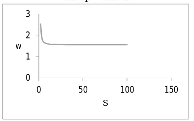
Fig.2 Through thickness variation of Transverse displacement of isotropic steel beam subjected to uniformly distributed load for various aspect ratios.
Fig3 Through thickness variation of In-plane Normal stress of isotropic steel beam subjected to uniformly distributed load for aspect ratio 4.
-0.5 -0.3 -0.1 0.1 0.3 0.5
-20 -10 0 10 u 20
z/h
0 1 2 3
0 50 100 150
w
S
-0.5 -0.3 -0.1 0.1 0.3 0.5
-20 -10 0 10 20
z/h
[image:6.612.191.424.566.698.2]©IJRASET 2015: All Rights are Reserved
[image:7.612.176.460.58.200.2]
89
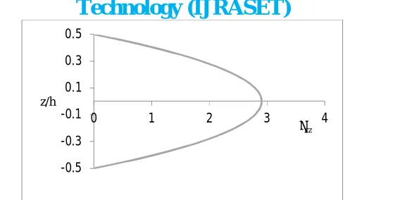
Fig.4 Through thickness variation of Transverse stress of isotropic steel beam subjected to uniformly distributed load for aspect ratio 4.
TABLE III
Comparison of In-plane displacement (u), transverse displacement (w), in-plane normal stress (
x) and transverse shear stress(
zx) in isotropic steel beam subjected to linearly varying load for aspect ratio 4 and 10.S THEORY u w x
CR zx
4
Sayyad and Ghugal 8.243 0.902 6.127 1.441
Reddy 8.252 0.903 6.1315 1.454
Timoshenko 8 0.903 6 0.9845
Bernoulli-Euler 8 0.7815 6 -
Timoshenko &
Goodier 7.9 0.8925 6.1 1.5
Present 8.25195 0.90295 6.13155 1.45405
10
Sayyad and Ghugal 125.615 0.8005 37.6295 3.656
Reddy 125.635 0.801 37.634 3.6805
Timoshenko 125 0.801 37.5 2.461
Bernoulli-Euler 125 0.7815 37.5 -
Timoshenko&
Goodier 124.75 0.799 37.6 3.75
Present 125.6367 0.80075 37.6337 3.68025
TABLE IV
In-plane displacement (u), transverse displacement (w), in-plane normal stress (
x) and transverse shear stress (
zx) inisotropic steel beam subjected linearly varying load for various aspect ratios.
S u w x
CR zx
2 1.123 1.26575 1.63055 0.7076
4 8.252 0.90295 6.13155 1.45405
10 125.637 0.80075 37.6337 3.68025
25 1954.705 0.78435 234.515 9.22415
50 15628.053 0.78205 937.661 18.4555
100 125005.242 0.78145 3750.24 36.9146
-0.5 -0.3 -0.1 0.1 0.3 0.5
0 1 2 3 4
z/h
Fig.5: Through thickness variation of In-plane displacement of isotropic steel beam subjected to linearly varying load and for aspect ratio 4.
Fig.6 Through thickness variation of Transverse displacement of isotropic steel beam subjected to linearly varying load for various aspect ratios.
Fig.7 Through thickness variation of In-plane Normal stress of isotropic steel beam subjected to linearly varying load for aspect ratio 4.
Fig.8 Through thickness variation of Transverse stress of isotropic steel beam subjected to linearly varying load for aspect ratio 4.
-0.5 -0.3 -0.1 0.1 0.3 0.5
-10 -5 0 5 10
z/h
u
0 0.5 1 1.5
0 50 100 150
w
S
-0.5 -0.3 -0.1 0.1 0.3 0.5
-10 -5 0 5 10
z/h
ỡx
-0.5 -0.3 -0.1 0.1 0.3 0.5
0 0.5 1 1.5 2
z/h
©IJRASET 2015: All Rights are Reserved
91
TABLE V
Comparison of effect of volume fraction exponent on the dimensional stresses and displacements of FGM beam subjected to
uniformly distributed load.
S K u w x
CR zx
Ceramic 0.0059 25.3147 3.2611 1.4152
1 4.6898 3.7666 4.409 0.6104
2 2 6.3081 4.8868 5.4665 0.6419
4 7.2076 5.8794 6.7083 0.6352
10 7.5202 6.9486 7.6662 0.4892
Metal 0.0321 25.3147 3.2611 1.4152
Ceramic 0.0434 18.0588 12.2631 2.9081
1 38.9755 3.293 17.4438 1.2387
4 2 52.6531 4.2351 23.0677 1.3049
4 60.956 4.9334 25.5433 1.2938
10 64.6458 5.6498 -48.108 0.9843
Metal 0.2358 18.0588 12.2631 2.9081
Ceramic 0.6612 16.0149 75.2675 7.3605
1 615.4867 3.1601 105.1591 3.1143
10 2 832.4783 4.0522 138.904 3.2833
4 967.2228 4.6678 254.6651 3.2586
10 1030.182 5.2849 219.9175 2.5123
Metal 3.5896 16.0149 75.2674 7.3605
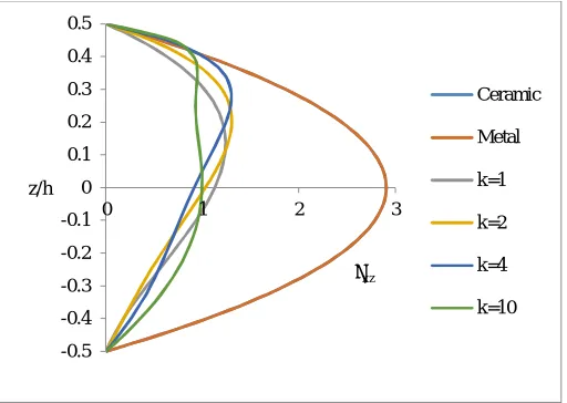
[image:9.612.66.544.135.631.2]
Fig.9a and 9b Variation of In-plane displacement ‘u’ for through thickness of beam subjected to uniformly distributed load
for the aspect ratio 4 for ceramic and metalfor ceramic and metal (9a) and with different fraction exponent (9b).
-0.5 -0.4 -0.3 -0.2 -0.1 0 0.1 0.2 0.3 0.4 0.5
-0.4 -0.2 0 0.2 0.4
z/h
u
Ceramic
Metal
-0.5 -0.4 -0.3 -0.2 -0.1 0 0.1 0.2 0.3 0.4 0.5
-50 0 50 100
z/h
u
k=1
k=2
k=4
Fig. 10 Variation of Transverse displacement ‘w’ through thickness of beam subjected to uniformly distributed load for the various aspect ratios.
[image:10.612.187.443.509.691.2]
Fig 11a and 11b Variation of In-plane Normal stress through thickness of beam subjected to uniformly distributed load for the aspect ratio 4 for ceramic and metal (11a) and for different fraction exponent (11b).
Fig 12 Variation of In-plane Transverse stress through thickness of beam subjected to uniformly distributed load for the aspect ratio 4.
0 5 10 15 20 25 30
0 5 10 15
w
S
Ceramic
k=1
k=2
k=4
k=10
Metal
-0.5 -0.4 -0.3 -0.2 -0.1 0 0.1 0.2 0.3 0.4 0.5
-20 -10 0 10 20
z/h
ỡx
Ceramic
Metal
-0.5 -0.4 -0.3 -0.2 -0.1 0 0.1 0.2 0.3 0.4 0.5
-150 -100 -50 0 50
z/h
ỡx
k=1
k=2
k=4
k=10
-0.5 -0.4 -0.3 -0.2 -0.1 0 0.1 0.2 0.3 0.4 0.5
0 1 2 3
z/h
τxz
Ceramic
Metal
k=1
k=2
k=4
©IJRASET 2015: All Rights are Reserved
93
TABLE VI
Comparison of effect of volume fraction exponent on the dimensional stresses and displacements of FGM beam subjected to
linearly varying load.
S k u w x
CR zx
Ceramic 0.00295 12.65735 1.63055 0.7076
1 2.3449 1.8833 2.2045 0.3052
2 2 3.15405 2.4434 2.73325 0.32095
4 3.6038 2.9397 3.35415 0.3176
10 3.7601 3.4743 3.8331 0.2446
Metal 0.01605 12.65735 1.63055 0.7076
Ceramic 0.0217 9.0294 6.13155 1.45405
1 19.48775 1.6465 8.7219 0.61935
4 2 26.32655 2.11755 11.53385 0.65245
4 30.478 2.4667 12.77165 0.6469
10 32.3229 2.8249 -24.054 0.49215
Metal 0.1179 9.0294 6.13155 1.45405
Ceramic 0.3306 8.00745 37.63375 3.68025
1 307.7434 1.58005 52.57955 1.55715
10 2 416.2392 2.0261 69.452 1.64165
4 483.6114 2.3339 127.3326 1.6293
10 515.0908 2.64245 109.9588 1.25615
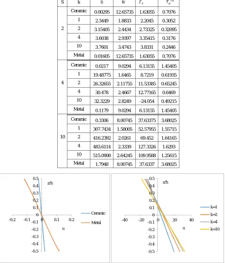
[image:11.612.66.522.124.658.2]Metal 1.7948 8.00745 37.6337 3.68025
Fig.13a and 13b Variation of In-plane displacement ‘u’ for through thickness of beam subjected to linearly varying load for the aspect ratio 4.
-0.5 -0.4 -0.3 -0.2 -0.1 0 0.1 0.2 0.3 0.4 0.5
-0.2 -0.1 0 0.1 0.2 z/h
u
Ceramic
Metal
-0.5 -0.4 -0.3 -0.2 -0.1 0 0.1 0.2 0.3 0.4 0.5
-40 -20 0 20 40
z/h
u
k=1
k=2
k=4
Fig.14 Variation of Transverse displacement ‘w’ through thickness of beam subjected to linearly varying load for the various aspect ratios.
Fig.15a and 15b Variation of In-plane Normal stress through thickness of beam subjected to linearly varying load for the aspect ratio 4 for ceramic and metal (15a) and for volume fraction (15b).
Fig.16 Variation of Transverse stress through thickness of beam subjected to linearly varying load for the aspect ratio 4.
VI. DISCUSSIONS
For FG beams it is important to observe that the stresses in fully ceramic beam and fully metallic beam are same. This is because the material is totally homogeneous and the stresses do not depend on the modulus of elasticity. The results could not be compared with any other theory as such work is not conducted earlier. However, the theory gives results for the isotropic beam and those results are compared and found accurate. Thus, the theory is valid.
Table V and VI shows the comparison of the maximum displacement and stresses for FGM subjected to uniformly distributed and linearly varying load. The comparison is represented for the aspect ratio 4 and 10. The present theory
0 2 4 6 8 10 12 14
0 5 10 15
w
S
Ceramic
k=1
k=2
k=4
k=10
Metal
-0.5 -0.4 -0.3 -0.2 -0.1 0 0.1 0.2 0.3 0.4 0.5
-10 -5 0 5 10
z/h
ỡx
Ceramic
Metal
-0.5 -0.3 -0.1 0.1 0.3 0.5
-60 -40 -20 0 20
z/h
ỡx
k=1
k=2
k=4
k=10
-0.5 -0.4 -0.3 -0.2 -0.1 0 0.1 0.2 0.3 0.4 0.5
0 0.5 1 1.5
z/h
τxz
Ceramic
k=1
k=2
k=4
k=10
©IJRASET 2015: All Rights are Reserved
95
overestimates and other higher Order theories underestimate the results of in-plane displacement as compared to those of exact solution. Through thickness variation of in-plane displacement for isotropic beam subjected to sinusoidal load is shown in Fig.3.5. The HSDT and FSDT overestimate the value of maximum transverse deflection. The ETB underestimates the value of maximum transverse displacement for aspect ratios 4 and 10 respectively due to neglect of transverse shear deformation. . The values of normal bending stress predicted by FSDT and ETB are identical for all aspect ratios. Table II and IV shows the
In-plane displacement (u), transverse displacement (w), in-In-plane normal stress (
x) and transverse shear stress (
zx) in isotropicsteel beam subjected to sinusoidal load for aspect ratios of 2,4,10,25,50 and 100.
VII. CONCLUSIONS
Results show that the present theory gives similar results with the existing higher order shear deformation theories with more number of unknowns. Thus, this theory is comparable. The number of unknowns and governing differential equations of the present theory is reduced to three. The results of in-plane normal stresses and transverse shear stresses are identical for the all three materials i.e. ceramic, metal and steel for all loading cases. This shows that the stresses are independent of modulus of elasticity when the material is homogeneous. For isotropic beam, the results of displacements and stresses obtained by present theory for all loading cases are in excellent agreement with those of exact solution. The present theory satisfies the shear stress free surface condition on top and bottom surfaces of the beam. Theory is variationally consistent. There is no need of shear correction factor.
VIII. ACKNOWLEDGEMENT
We would like to express our gratitude to Prof.A.S.Sayyad, Department of Civil Engineering, SRES’s College of Engineering Kopargaon, for his valuable guidance related to this topic.
REFERENCES
[1] Meghare TK and Jadhao PD, “A Simple Higher Order Theory for Bending Analysis of Steel Beams”, SSRG International Journal of Civil Engineering (SSRG-IJCE), ISSN:2348-8352.
[2] Shimpi RP., Patel HG. and Arya H., “New First-Order Shear Deformation Plate Theories”,Journal of Applied Mechanics, MAY 2007, Vol. 74 / 523. [3] Ghugal YM and Dahake AG, “Flexural analysis of deep beam subjected to parabolic load using refined shear deformation theory”, Applied and
Computational Mechanics 6 (2012) 163–172.
[4] Sayyad AS and Ghugal YM, “Flexure of Thick Beams using New Hyperbolic Shear Deformation Theory”, International Journal of Mechanics, Issue 3, Volume 5, 2011.
[5] Mantari JL., Oktem AS. and Soares CG., “A new trigonometric shear deformation theory for isotropic, laminated composite and sandwich plates”, International Journal of Solids and Structures , 49(2012)43-53.
[6] Wattanasakulpong and Ungbhakorn, “Free Vibration Analysis of Functionally Graded Beams with General Elastically End Constraints by DTM”, World Journal of Mechanics, 2012, 2, 297-310.