©IJRASET: All Rights are Reserved
1517
Performance of Building for Different Orientation
of Shear Wall
Sumit Singh Bhadauria1, Asst. Prof. Rashmi Singh2
1Student M. Tech Civil Engineering, Amity University Madhya Pradesh, 2Asst. Prof. Department of Civil Engineering, Amity
University Madhya Pradesh
Abstract - In this study we have considered shear wall system for the stability of structure against lateral forces. Shear wall is a vertical member which can resist moment, shear and axial load arising due to gravity and lateral loads. It offers adequate rigidity to the structure to withstand seismic forces and is also helpful in resisting lateral loads caused due to earthquake. Provision of shear wall is itself helpful in providing seismic stability and also orientation of shear plays a crucial role in restricting lateral forces coming on the structure. In this study we have placed shear wall at different orientation or position and identified the best position of shear wall in the building by analyzing the results in terms of storey drift, lateral displacement and base shear. For the analysis we have prepared 4 models of building with G+12 storey height with different position of shear walls. We have analyzed all the models by response spectrum method of seismic analysis in STAAD.Pro v8i software. The comparison of all four models with different location of shear wall has been done with respect to story drift, base shear and lateral displacement.
Key Words- Shear wall, Lateral Displacement, storey drift, base shear, response spectrum, Staad Pro v8i.
I. INTRODUCTION
The necessary earthquake resistant capacity in a multi-storied building can be achieved by providing adequate stiffness, strength and ductility in the building and shear wall provides an optimal means of achieving the basic criteria of design. Shear wall is a vertical member which can restrict combination of moment, shear and axial loads. It imparts sufficient rigidity against lateral loads and provides adequate stiffness to the structure. Shear wall is an element which acts as a vertical cantilever used generally in multi storied building to resist lateral forces like wind, storm, and earthquake. These walls are in general continuous element starting from the foundation and go up to the highest point of the building. However, it may also be curtailed at intermediate height. For buildings over 30 stories, shear wall has been an essential element to ensure economy and minimize the lateral deflection. When shear wall is used along with moment resisting frame in a structure, it is called dual structural system and in this system the loads are resisted by both frame & Shear wall. The Contribution of Shear wall in resisting overturning moments, storey shear and storey shear forces depends upon the geometric configuration, materials used, orientation and location within the plane of the building.
II. METHODOLOGY
In this study method used for the analysis of building considering dead load, live load, seismic load is response spectrum method.
A. Response Spectrum Method
The main purpose of the response spectrum analysis is to identify the seismic forces of the design, with the different building levels with the height of the building and its part with different lateral load resisting elements. This method is based on the assumption that the dynamic response of the structure can be found by considering the independent response of each natural mode of vibration and then computing the total reaction. For analysis, the mass of the structure is considered lumped at the floor level and only the displacement is allowed on each floor. Thus for planer systems, only one degree of freedom per floor and for three degree of dimensional analysis three degrees of freedom per floor i.e. two translation and one angle of twist around the vertical axis must be considered. Now the design lateral force at each mode is calculated by the formula, given in CL.7.8.4.5(c), of IS 1893 (part I):2002
B. Software Used
©IJRASET: All Rights are Reserved
1518
engineering i.e development of model, structural analysis, design of building, visualization. This is based on the fundamentals of concurrent engineering in STAAD we can do modeling, assign the properties to the elements of a building, analysis can be done, we can view the modeled structure in 3D view. There are various options available in fundamental graphics environment.
Analysis and design by STAAD-Pro STAAD-Pre Graphics Input Generation STAAD-Post Graphical Post processing
III. BUILDING MODELING AND ANALYSIS
In this dissertation we will consider a G+12 building having 9 bays in X direction and 7 bays in Z direction having different orientation of shear wall.
A. Shear Wall Placed in Longitudinal Direction At Middle of Outer Periphery
Storey – G+12
Beam size – 230mm*350mm Column size – 1100mm*1100mm Thickness of slab – 125mm Shear wall thickness – 300 mm
Fig1: Front view Fig 2: 3D view
B. Shear Wall Placed in Transverse Direction At Middle of Outer Periphery
Storey – G+12
©IJRASET: All Rights are Reserved
1519
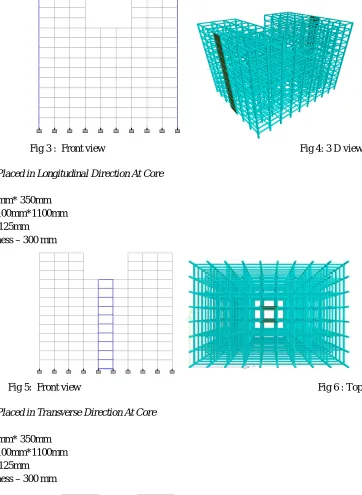
Fig 3 : Front view Fig 4: 3 D view
C. Shear Wall Placed in Longitudinal Direction At Core
Storey – G+12
Beam size – 230mm* 350mm Column size – 1100mm*1100mm Slab thickness – 125mm
[image:4.612.142.300.82.243.2]Shear wall thickness – 300 mm
Fig 5: Front view Fig 6 : Top view
D. Shear Wall Placed in Transverse Direction At Core
Storey – G+ 12
Beam size – 230mm* 350mm Column size – 1100mm*1100mm Slab thickness – 125mm
[image:4.612.110.472.87.582.2]Shear wall thickness – 300 mm
©IJRASET: All Rights are Reserved
1520
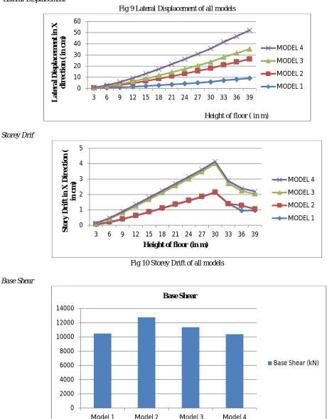
A. Lateral Displacement
Fig 9 Lateral Displacement of all models
B. Storey Drif
[image:5.612.57.517.97.687.2]
Fig 10 Storey Drift of all models
C. Base Shear
[image:5.612.128.518.496.695.2]
Fig 11 Base Shear of all models
0 10 20 30 40 50 60
3 6 9 12 15 18 21 24 27 30 33 36 39
Late r al D is p lac e m e n t in X d ir e c ti o n ( in c m )
Height of floor ( in m)
MODEL 4 MODEL 3 MODEL 2 MODEL 1 0 1 2 3 4 5
3 6 9 12 15 18 21 24 27 30 33 36 39
S to r y D r ift in X D ir e c ti o n ( in c m )
Height of floor (in m)
MODEL 4 MODEL 3 MODEL 2 MODEL 1 0 2000 4000 6000 8000 10000 12000 14000
Model 1 Model 2 Model 3 Model 4
Base Shear
©IJRASET: All Rights are Reserved
1521
V. CONCLUSION
A. Maximum lateral displacement in X direction is 17.1728 cm in model 2 (Shear wall in transverse direction at outer periphery)
B. Minimum lateral displacement in X direction is 2.1120 cm in model 3 (Shear wall at longitudinal direction at core)
C. Maximum storey drift in X direction is 2.1351 cm in model 1(Shear wall in longitudinal direction at outer periphery)
D. Minimum storey drift in X direction is .0841 cm in model 2 (Shear wall in transverse direction at middle of outer periphery).
E. Maximum base shear is 12762.24 kN in model 2 (Shear wall in transverse direction at middle of outer periphery)
F. Minimum base shear is 6183.35 kN in model 4 (Shear wall in longitudinal direction at core)
From the following results it can be concluded that model 3 has minimum lateral displacement, model 2 has minimum storey drift and maximum base shear.
REFERENCES
[1] Anil Baral and Dr. Sk. Yajdani, “Seismic Analysis of RC Framed Building for Different Position of Shear wall” ,International Journal of Innovative Reseach in Science, Engineering and Technology(IJIRSET). Vol 4, pp. 3346-3353, May 2015.
[2] VarshaR.Harne, “Comparative Study of Strength of Rc Shear wall at Different Location on Multi-storied Residential Building” ,International Journal of Civil Engineering Research(IJCER). Vol 5, pp. 391-400, 2014.
[3] R.S.Mishra, V.Kushwaha and S.kumar, “A Comparative Study of Different Configuration of Shear Wall Location in Soft Story Building Subjected to Seismic Load” ,International Research Journal of Engineering and Technology(IRJET). Vol 2, pp. 513-519, October 2015.
[4] AnshulSud, Raghav Singh Shekawat and PoonamDhiman, “Effect of different shear wall configurations on seismic response of a moment-resisting frame” ,European Scientific Jounal(ESJ), pp. 139-145, May 2014.
[5] RakshitPatil, Avinash S Deshpande and ShrishailSambanni, “Optimal location of shear wall in high rise building subjected to seismic loading” ,International Journal For Research in Engineering(IJTRE). Vol 3, pp. 2678-2682, June 2016.
[6] N. VenkataSairam Kumar, R. SurendraBabu and L. UshaKranti, “Shear walls – A review”, International Journal of Innovative Research in Science, Engineering and Technology (IJIRSET).Vol.3, pp.9691-9694, February 2014.
[7] Mr. AmeyDhondopantKulkarni, “Assessment of Location and optimum percentage of shear wall for typical plans” ,International Journal of Engineering Development and Research(IJEDR). Vol 4, pp. 985-989, 2016.
[8] \RupaliGoud and SumitPahwa, “Study of Moment and Shear force in Building with various Location of Lift Core Shear Wall under Earthquake load” ,International Journal of Latest Trends in Engineering and Technology(IJLTET). Vol 6, pp. 380- 387, January 2016.
[9] B, SanganiSanikumar. And Prajapati, G. I, “Structural Economics of Earthquake resistant design of RC building with and without shear wall”, ICI journal, April- June 2013.\