DEVELOPMENT OF A LOW COST CAR OVER
SPEED CHECKING SYSTEM USING RFID TAG
Agbo David O.*, Madukwe Chinaza A.**, Shittu Dodo H. ***
*, **
Department of Electrical/Electronics Engineering, University of Agriculture, P.M.B.2373, Makurdi, Benue State, Nigeria.
***
Department of Works, Federal University of Technology, Lafia, Nasarawa State, Nigeria. Email of the corresponding author: [email protected].
DOI: 10.29322/IJSRP.8.6.2018.p7863
http://dx.doi.org/10.29322/IJSRP.8.6.2018.p7863
Abstract-Nowadays, the rate of road accident has increased tremendously. The drivers cause majority of these accidents by over speeding. In order to address the stated problem above, the problem, “car over speed checking system using RFID tag” was proposed. In this project, each car has his own tag with Unique Identification (UID), two RFID reader positioned at a distance of hundred meters and a maximum speed of sixty kilometer per hours was chosen. Two Arduino UNOs were used, one at the Transmitter end and the other at the Receiver end which communicate wirelessly via Radio Frequency (RF). When a car is at the range of the reader at the transmitter end, the transmitter reader reads the tag, store the tag UID and the time the tag was read in the arduino memory, the system then sends the tag UID and time the tag was read to the Receiver end. When the same tag is at the range of the receiver reader at the receiving end, the reader reads the tag, store its UID and time tag was read. After then, it then calculate the time difference. If the time is less than six seconds, it indicate OVER SPEEDING and a Buzzer is turned ON. However, if the time is greater or equal to six seconds, nothing is done. The information are displayed on the LCD.
Keywords: Speed, Arduino, RFID module, Receiver Module and Transmitter Module
I. INTRODUCTION
Road facilities are a major concern in the developed world. Recent studies show that one third of the number of fatal or serious accidents are associated with over speeding, as well as changes in the roadway (like the presence of roadwork or unexpected obstacles). Reduction of the number of accidents and mitigation of their consequences are a big concern for traffic authorities, the automotive industry and transport research groups. (Ankita et al., 2012).
One important line of action consists in the use of advanced driver assistance systems (ADAS) which are acoustic, hectic or visual signals produced by the vehicle itself to communicate to the driver the possibility of a collision. These systems are somewhat available in commercial vehicles today, and future trends indicate that higher safety will be achieved by automatic driving controls and a growing number of sensors both on the road infrastructure and on the vehicle itself. A prime example of driver assistance systems is cruise control (CC), which has the capability of maintaining a constant user preset speed. Its evolution, the adaptive cruise control (ACC), which adds to CC the capability of keeping a safe distance from the preceding vehicle. The drawback of these systems, is that they are not independently capable of distinguishing between straight and curved parts of the road, where the speed has to be lowered to avoid accidents. (Manjunath and Chandrashekara, 2015).
Radio Frequency Identification (RFID) tags, or simply "tags", are small transponders that respond to queries from a reader by wirelessly transmitting a serial number or similar identifier. They are heavily used to track items in production environments and to label items in supermarkets. They are usually thought of as an advanced barcode. However, their possible area of use is much larger. (Gurjot et al. 2012).
II. LITERATURE REVIEW
Most road accidents occur due to over speed and rash driving of vehicles on public roads. The rate of accidents has increased as more vehicles are being manufactured and sold. Usually the drivers drive the vehicles at high speed without considering the public in speed limited areas. Even though the traffic police control them, we cannot achieve full response from them. Thus, the need to monitor those areas at all time to regulate their speed using RFID technology.
Lujaina et al. (2014) proposed an automobile speed violation detection system using RFID and GSM technologies. The system has two RFID readers along with a passive tag that is attached to the vehicle via PIC18f45k22 and GSM is utilized to notify the vehicle's owner and Police through Short Message Service (SMS). Furthermore, a picture of a vehicle is taken via the Camera and a fine is charged when the speed limit is exceeded.
Eswaramoorthy and Arunkumar (2014) proposed intelligent vehicle control based on identification of road signs by solar powered RFID transponders. They used an RFID reader present in the vehicle to sense the vehicle speed limit on the tag (attached to the speed limit signboard) as a reference speed input, here, the active RFID tag is used in the signboard which has a battery charged using the solar panel and this reference speed is given to the Electronic Control Unit (ECU). Meanwhile the vehicle speed sensor present in the wheel gives the actual speed of the vehicle on road. The output of this ECU unit is given to the proposed braking system present in the automobiles.
Leena et al. (2014) proposed an automatic speed control of vehicles using RFID. In this paper, the speed of the vehicles can be controlled within certain limit in restricted zones without interruption of the drivers. The RFID reader is attached to the vehicle and the RFID tags are at the zones. These tags are programmed to send a coded signal when the reader comes in proximity. Whenever the vehicles enter into these zones their receivers will receive this code and the speed of the vehicles is controlled automatically with the help of the micro controller unit present inside the vehicle. The tags are placed at the beginning and the end of the regions for which the speed should be reduced.
Farrukh et al. (2015) designed and implemented a smart vehicles speed monitoring system-using RFID where the monitoring system stations are placed on different locations. Each car has its RFID tag and each stations through RFID and cameras system is saving information of vehicles like vehicle identity, time when it is crossing, speed, picture etc. RFID reader will save information for all these vehicles, which are passing through this RFID reader. Every station is connected to main data base station, which is collecting data from all these stations.
Pulkit et al. (2017) presented speed check and over speed detector. Their idea was to calculate the speed of sound and the time it takes to reach the object (time taken to receive echo/2) to determine the range of the object. Here, the trigger signal is recorded at specified time interval (at two different time intervals) for every moving object detected. The difference of the distances recorded is divided by the difference of the time at which both the trigger signals are received. This gives the speed of the moving object. The controller further sends the value to the speed recorded to the controller placed near the display board. This is how speed of the target vehicle is displayed on the LED board. If the speed calculated is above the predefined limit, a WARNING message is sent to the display, which triggers the camera connected to the raspberry pi Arduino to capture the image of the vehicle along with its number plate. The image is sent as a message or mail to a server maintained by the authority person or sent to drop box using cloud computing.
There are many applications of RFID, which are being used in cars. In this present project, that is, car over speed checking system using RFID module (reader and tag) (RFID Technology, 2017). This is achieved with the help of two readers positioned at a distance. Each car has its RFID tag, the monitoring system stations is placed at different locations. The RFID reader save the information of the car such as time it is crossing, speed and display the information on the LCD. The minimum time it will take the car to pass the two readers, have already been calculated with the help of the specified speed and the distance. Using the Arduino Uno (Arduino data sheet, 2017), if it takes any car lesser time to pass the specified time, it indicate over speeding.
II. MATERIALS AND METHODS
The Block diagram of the system is shown in Figure 1. It comprises two major sections; the first section is the transmitting of the car over speed checker and the second section is the receiver section of the car over speed checker.
(a): Transmitting Block Diagram of a car over speed Checker.
(b): Receiving Block Diagram of a car over speed Checker. Figure 1: Block Diagram of a car over speed Checker.
ARDUINO
UNO
Power supply
RFID Reader
RFID Tag
RF Transmitter
Power Supply
ARDUINO
UNO
RF Receiver
LCD Display
RFID Reader
Over Speed
The circuit shown in the Figure 3a and 3b is the transmitter and receiver of the car over speed checker. In transmitter section of the car over speed checker, the RFID Reader was connected to pin 8, 9, 10, 11, 12 and 13. In the void loop section, the Arduino was programmed to continuous looping till it has read a tag and store the time in a variable start, the UID (Unique Identification) number and stores it in the variable content and then transfer the data serially to the receiver through RF module connected to pin 1.
The receiver part of the code was written by creating a new project in the Arduino Integrated Development Environment (IDE) []. The LCD library, the RFID library, the virtual wire library were initialized. In the void set up section, pin 8 was declared for buzzer. Pin 2, 3, 4, 5, 6 and 7 was declared for LCD and pin 8, 9, 10, 11, 12 and 13 was declared for RFID module. Also, RF module was declared for pin 1. In the void loop section, the Arduino is programmed to continuous looping and wait till a data is received through the virtual wire Read function, proceed to wait, then scan a tag and compared the scanned UID with the received one to confirm the identity. The Arduino then proceed to check the time difference. If the difference is less than the set time, it should send a HIGH to the buzzer but if the difference is greater than or equal to the set time, it should send a LOW to the buzzer. This is then followed by a flash of an LED and a display of UID on the LCD screen. The code was burn into the Arduino by first connecting the USB cord to the computer port by selecting the board and the port that is, the COM pin which can be found under the tools in Arduino IDE. Then upload it by clicking the upload command in the Arduino Integrated Development Environment (IDE).
The flowchart of the program for the system is shown in figure 3 and 4.
(a) Transmitting circuit diagram. (b) Receiving circuit diagram.
Figure 2: Car over speed checker circuit diagram.
In our study, two RFID reader are placed 100𝑚 (0.1𝑘𝑚) apart and a maximum speed of 60𝑘𝑚𝑝𝑒𝑟ℎ𝑜𝑢𝑟 is specified for each car. That is, distance 𝑆= 100𝑚 and maximum speed𝑉= 60𝑘𝑚/ℎ𝑟.
𝑇𝑖𝑚𝑒𝑡𝑎𝑘𝑒𝑠=𝑉𝑆 ………..1.0
However, distance between two readers is 0.1km and the maximum speed is 60km per hour. By substituting these values into equation (1.0), we have minimum time taken to be:
𝑇=0.160 = 0.001667 ℎ𝑜𝑢𝑟.
Therefore, the minimum time taken between the two readers is approximately (6 seconds).
If it takes any car less than (6 seconds) to pass the two readers, the system indicates OVERSPEEDING.
3.3V OUT 3 .3 V O U T A N A L O G IN A TM EG A 328P -P U 1 121 R e se t B T N O N w w w .T h e E n g in e e rin g P ro je c ts .c o m PD0/RXD PD1/TXD PD2/INT0 ~ PD3/INT1/OC2B PD4/T0/XCK ~ PD5/T1/OC0B ~ PD7/AIN1 PC5/ADC5/SCL PC4/ADC4/SDA PC3/ADC3 PC2/ADC2 PC1/ADC1 PC0/ADC0 PB0/ICP1/CLKO ~ PB1/OC1A ~ PB2/OC1B ~ PB3/MOSI/OC2A PD7/AIN1 PB4/MISOPB5/SCK AREF G e n u in o U N O 0 1 2 3 4 5 6 7 8 9 10 11 12 13 A5 A4 A3 A2 A1 A0 GEN1 GENUINO UNO M O S I 6 M IS O 5 N C 4 G N D 3 R S T 2 S C K 7 3 .3 V 1 S D A 8 RFID1 RFID MODULE VI
1 VO 3
G N D 2 U1 7805 B2 9V microcontrolandos G N D D A TA V C C AN T U2 MODULO TX G N D 3.3V OUT 3.3 V O U T G N D A N A L O G IN ATM EG A3 28P-P U 112 1 R es e t B T N O N w w w .T h e E n g in e e r in g P r o je c ts .c o m PD0/RXD PD1/TXD PD2/INT0 ~ PD3/INT1/OC2BPD4/T0/XCK ~ PD5/T1/OC0B ~ PD7/AIN1 PC5/ADC5/SCL PC4/ADC4/SDA PC3/ADC3 PC2/ADC2 PC1/ADC1 PC0/ADC0 PB0/ICP1/CLKO ~ PB1/OC1A ~ PB2/OC1B ~ PB3/MOSI/OC2A PD7/AIN1 PB4/MISOPB5/SCK AREF G e n u in o U N O 0 1 2 3 4 5 6 7 8 9 10 11 12 13 A5 A4 A3 A2 A1 A0 GEN1 GENUINO UNO D 7 1 4 D 6 1 3 D 5 1 2 D 4 1 1 D 3 1 0 D 2 9 D 1 8 D 0 7 E 6 R W 5 R S 4 V S S 1 V D D 2 V E E 3 LCD1 LM016L BUZ1 BUZZER M O S I 6 M IS O 5 N C 4 G N D 3 R S T 2 S C K 7 3 .3 V 1 S D A 8 RFID1 RFID MODULE VI
1 VO3
G N D 2 5V REGULATOR 7805 B2 9V R1 330 D1 LED-GREEN m ic rocon trolandos G N D O U T V C C V C C G N D G N D A N T U1 MODULO RX START
[image:4.595.41.473.662.833.2]
YE
Figure 3: Receiving flow chart of a car over speed checker.
Figure 4: Transmitting flow chart of a car over speed checker.
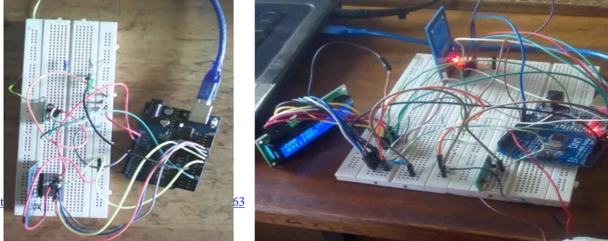
III. RESULTS AND DISCUSSION The hardware construction displaying connections is shown in figure 5a and 5b.
Wait, Read and Store the UID of the Card.
Note the Time (T
2) Card was read Again.
Calculate Time
T = (T2
−
T1)
Is the Time T ‹ 6 seconds?
Do Nothing (Normal Speed)
ON the Buzzer and LED (OVERSPEEDING)
Display the Card UID on the LCD.
Yes
No
START
Initialize all the needed Ports.
Wait, Read and Store the UID of the Card.
Figure 5: car over speed checker on bread board.
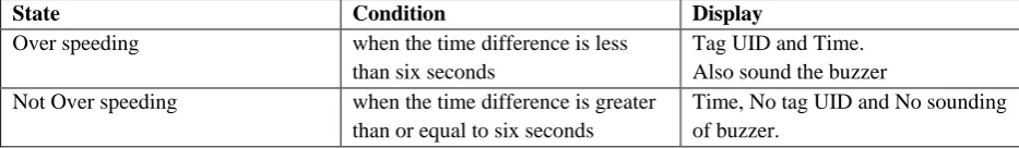
[image:5.595.126.563.351.445.2]When the circuit is successfully powered, the display on the LCD showing that the reader is reader to scan a tag is as shown in figure 6.
Figure 6: Initialization process
[image:5.595.64.501.494.715.2]When the car is at the range of the reader at the transmitting end, the reader reads the tag UID and the time the tag was read, it then send the tag UID and time wirelessly to the receiver. When the same tag is at the range of the reader at the receiving end, the reader reads the tag and the time again. It then find the time difference, if the time is less than six seconds, it indicate Over speeding, the buzzer is turned ON and the tag UID is displayed on an LCD as shown in figure 7.
Figure 7: Display of tag UID and time of cars that over speed
But if the time difference between the transmitting end and the receiving end is greater than or equal to six seconds, it indicate that the car did not over speed and the buzzer is not turned ON. The display on an LCD is as shown in figure 8.
Figure 8: Display of time of cars that do not over speed
Table 1: The state of each car that passes the device
State Condition Display
Over speeding when the time difference is less than six seconds
Tag UID and Time. Also sound the buzzer Not Over speeding when the time difference is greater
than or equal to six seconds
Time, No tag UID and No sounding of buzzer.
VI. CONCLUSION
Car over speed checking system using RFID tag will be a great solution in reducing road accidents through various charges that will be made by the police. It is now an established fact that the aim of this project work has been fully achieved but there is a room for improvement if the recommendation below can be fully implemented.
(a): The Transmitter of car over
speed checker
[image:5.595.44.492.498.603.2] [image:5.595.31.498.623.691.2]REFERENCES
Ankita, M., Jyoti, S., Harshala, B., Priyanka, S. and Pranav, P. (2012). Design of RF based Speed Control System for Vehicles.
International Journal of AdvancedResearch in Computer and Communication Engineering (IJARCCE), 1 (8): 583-586.
Eswaramoorthy, P. and Arunkumar, M. (2014). Intelligent Vehicle Control Based on
Identification of Road Signs by Solar Powered RFID Transponders. International Journal of
Research in Engineering and Technology (IJRET), 3 (1): 85-89.
Farrukh, H., Mohammad, A. S., and Omar, A. S. (2015). Smart Vehicles Speed Monitoring
System Using RFID. International Journal of Advanced Research in Electrical Electronics
And Instrumentation Engineering, 2 (2): 1860-1864.
Gurjot, S. G., Nancy, G., Gaurav, S. and Harsimranjit S. G. (2012). Intelligent Cars using RFID Technology. International Journal of Scientific and Engineering Research, 4 (7): 1-4.
Leena, T., Swetha, A. J., Seril, J., Arya, K. B., Tedik, N. and Obang, P. (2014). Automatic Speed Control of Vehicles Using RFID.
International Journal of Engineering and Innovative Technology (IJEIT), 3 (11): 118-120.
Lujaina, A.S. Nadarajan, J. and Jayavrinda, V. (2014). Automobile Speed Violation Detection
System using RFID and GSM Technologies. International Journal of Applied Information
Systems (IJAIS), 7 (6): 24-29.
Mandeep, K., Manjeet, S., Neeraj, M. and Parvinder, S. S. (2011). RFID Technology
Principles, Advantages, Limitations & Its Applications. International Journal of Computer and Electrical Engineering, 3 (1):
151-157.
Manjunath, C., and Dr Chandrashekara, K. (2015). Design & Analysis of Vehicle Speed Control Unit Using RF Technology.
International Advanced Research Journal in Science Engineering and Technology, 2 (8): 32-38.
Pulkit, S., Ankita, G., Komal, B., Devika, G., Jamini, S. and Neha, G. (2017). Speed Checker
And Overspeed Detector. International Research Journal of Engineering and Technology (IRJET), 4 (5): 1051-1053.
Singh, D. N. and Ravi, T. V. (2013). Vehicle Speed Limit Alerting and Crash Detection System At Various Zones. International Journal of Latest Trends in Engineering and Technology (IJLTET), 2 (1): 108-113.
Arduino data sheet, (2017), Retrieved from, https://datasheet.octopart.com/A000066-Arduino-datasheet-38879526.pdf
Arduino IDE (2018), Retrieved from, https://arduino.en.downloadastro.com/