© 2018, IRJET | Impact Factor value: 6.171 | ISO 9001:2008 Certified Journal | Page 4938
A Framework for Incorporating Dependency Structure Matrix in
Building Design Process
Athira Prasad
1, Jeevan Jacob
21
M.Tech Student, Dept. of Civil Engineering Mar Athanasius College of Engineering, Kothamangalam, Kerala, India
2
Associate Professor, Dept. of Civil Engineering, Mar Athanasius College of Engineering, Kothamangalam,
Kerala, India
---***---Abstract -
Design structure matrix (DSM) is a relativelynew approach to project management, used to represent, analyze dependencies among tasks and show the optimum order in which tasks are performed. It is an information exchange model that allows the representation of complex task or (team) relationships in order to determine a sensible sequence for the tasks being modeled. Sequencing of activities is influenced by the information dependency among the activities. One of the challenges in planning the sequencing of design activities is to decide on appropriate information or assumptions which can be made to break the interdependent activities (loops). This paper consists of identifying problems on design process through a case of DDSM and suggesting solutions for minimizing the problems.
Key Words: Design Structure Matrix, dependencies,
Sequencing, loops, DDSM
1. INTRODUCTION
The Architecture/Engineering/Construction (AEC) industry is one of the multidisciplinary domains in which collaboration among related parties is of utmost importance. There is a lack of research in the area of collaboration and flow of information between design professionals. Most of the current process modeling tools in the AEC industry does not enable analyses of iterative information cycles. Moreover, these tools represent the process at high levels, thus, they are inappropriate for multi-parameter problems like building design. Conventional network-based planning tools are not suitable for modeling the iterative process. Graph-based tools such as digraphs, Graphical Evaluation and Review Technique (GERT), and Petri nets can model these iterations; however, they all have practical limitations. A new method of matrix-based representation for the dependency modeling of the iterative design process called dependency structure matrix (DSM). As drawings are well-defined entities, the elements of the drawing DSM (DDSM) can be identified directly and the intricacies of deciding on the appropriate abstraction level, as in the case of activity DSM, are avoided [14]. The objective of this work is to develop a framework to formulate a DDSM and support this framework with a structured methodology that can be implemented on construction projects.
1.1 DEPENDENCY STRUCTURE MATRIX (DSM)
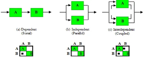
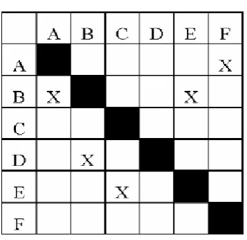
[image:1.595.317.556.631.730.2]The basic representation of activity DSM is a square matrix containing a list of activities in the rows and columns in the same order in a matrix form as shown in fig 2. The order of activities in the rows or columns in the matrix indicates the sequence of execution. The relationships between the activities are represented with an X mark in the off-diagonal cells. The activities have to be read along the column as ‘‘gives information to’’ and along the row as ‘‘needs information from’’. If any mark lies above the diagonal, it implies that an assumption has to be made to execute the corresponding sequence. The process of rearranging the order of activities by moving an entire row and column on either side (up/down and left/right) in such a way that the resulting matrix has marks either below the diagonal or close to the diagonal is called partitioning [13]. This process is mainly to minimize the number of assumptions. Here it is assumed that (for simplicity), there are no marks above the diagonal after partitioning process, which implies that there are no interdependent activities and loops. The diagonal cells generally have no value but the duration for each activity can be included. Even though DSM has been proved to be a powerful planning tool, its application in scheduling is very limited. Fig 1 shows the DSM representations of basic activity relationships. Because of the temporal ordering of the activities, sub diagonal matrix elements show feed forward information (such as the flow from activity A to activity B in the serial case). Super diagonal elements indicate feedback, the potential for iteration and rework in the process. Thus, if activities in rows (and corresponding columns) i and j of the DSM have no direct interfaces, entries ij and ji in the matrix will be zero or empty. If, on the other hand, both entries ij and ji are filled, this indicates two-way interdependency or coupling between the activities [8].
© 2018, IRJET | Impact Factor value: 6.171 | ISO 9001:2008 Certified Journal | Page 4939 Fig-2: A DSM Representation of a Project
2. LITERATURE SURVEY
Design Interface Management System (diMs)
The diMs methodology identifies and manages the design interfaces through formulating a DDSM. Because the process is incremental, data-intensive, and collaborative, a server-based prototype system was developed to facilitate the work flow of the process. The tool features multiple user authorization levels, access from distributed locations, automated alert messages through system generated e-mails, and report generation. The system can be hosted on the server at the design office and the data can be accessed through the web. ( Senthilkumar ,V. and Varghese K. ,2013).
Fast Track Project
Fast-tracking falls under the umbrella of concurrent engineering and is described as overlapping successive activities to reduce project duration. A more specific definition of fast-tracking is the compression of design and production schedules by overlapping activities.In the fast-track method some amount of overlap occurs between pairs of activities such as design and construction. (Issam M. Srour, 2012).
Engineering tool
Dependency Structure Matrix (DSM) is an effective tool in visualizing the complexities and interdependencies of a process architecture. The focus of the DSM model is on detecting the unnecessary interdependencies among tasks that can increase the operation time, reduce its effectiveness, and increase the risk of human error and to investigate how modern technology can aid in resolving the detected complexities. (Seyed M.M, 2016)
Integration of BIM and DSM
Building Information Modelling (BIM), one of the latest tools in building design, based on parametric modelling paradigm, allow the collaborators to be in physically distant locations
without face to face interaction. This amplifies complexity and need for improved design management. Explores the information flow in collaborative working of BIM and integrates DSM, the management tool that allows feedback and cyclic task dependencies, for improvement of design process. Parameters are identified as the level in which the information to be captured as input to DSM, from the fact that BIM is parametric and the parameterbased DSM is suitable for it. A suitable standard is required to represent BIM in order to interact with DSM. IFC is identified as the appropriate standard because it is an interoperable open format developed particularly for AEC industry. A framework to integrate DSM and BIM in IFC format is proposed to improve design process. ( Jacob , J. , 2011)
3. DSM OPERATIONS
The DSM method utilizes some operations to analyse information dependencies and to re-arrange system elements accordingly.
Partitioning is the process of re-ordering the DSM rows and columns so that the new arrangement does not contain iterations (i.e. the DSM is transformed into lower triangular form). For complex systems, it is often impossible to obtain a lower triangular form DSM by partitioning. In this case the aim is to move the feedback marks as close as possible to the diagonal so that fewer system elements are involved in the iteration cycle (this results in a faster development process)[1,2,16].
Tearing is the process of choosing the set of feedback marks that if removed from the matrix will render the matrix lower triangular. The marks that are removed from the matrix are called “tears.” Identifying the tears that result in a lower triangular matrix means that the set of assumptions that need to be made in order to start design process iterations. Having made these assumptions, no additional estimates need to be made. No optimal method exists for tearing, but it is recommended to use two criteria when making tearing decisions: 1. Minimal number of tears: The motivation behind this criterion is that tears represent an approximation or an initial guess to be used. Thus the number of these guesses should be reduced.
2. Confine tears to the smallest blocks along the diagonal: The motivation behind this criterion is that if there are iterations within iterations, these inner iterations are done more often. Therefore, it is desirable to confine the inner iterations to a small number of tasks.
© 2018, IRJET | Impact Factor value: 6.171 | ISO 9001:2008 Certified Journal | Page 4940
Banding is the addition of bands to a DSM to show independent (i.e. potentially parallel or concurrent) system elements. The collection of bands within a DSM constitutes the critical path of the system or project. Furthermore, one element within each band is often critical. Thus, fewer bands are preferred since they improve the concurrency of the system/project.
Clustering is the process of finding subsets of DSM elements (clusters) that are mutually exclusive or minimally interacting subsets. In other words, clusters absorb most, if not all, of the interactions internally and the interactions between separate clusters is eliminated or at least minimized [5].
4. DDSM FORMULATION
In order to formulate the Drawing Design Structure Matrix (DDSM), the following fundamental (conceptual) steps are proposed [13].
• DDSM will contain all drawings identified at a particular stage in the design process. However, the relationships between drawings are limited only to relationships where critical information constraints are identified by the interacting design teams.
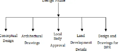
[image:3.595.39.279.599.705.2]• Relationship and interactions between teams can be effectively identified by enumerating the ‘physical interfaces’ between various systems, components and subcomponents. • A top-down approach which decomposes the project systems into appropriate component and subcomponent levels will facilitate identification of the physical interfaces between various systems, components and subcomponents. • A bottom-up approach which relates all the design interface parameters identified by the design teams with appropriate drawings as an input or output parameter, will establish the interface relationships among the drawings. • Drawing design phase consists of several stages as shown in fig 3.
Fig – 3: Main process under Design Phase
A characteristic of the design process in all areas of design is the use of a number of different types of drawings. The different types of drawings are associated with different
stages of the process with one type, the relatively unstructured and ambiguous sketch, occurring early in the process. Designers place great emphasis on the sketch often because it is thought to be associated with innovation and creativity. Because of this emphasis researchers have also begun to focus on the sketch and its role in design. Design activities include information exchange between different disciplines. It can be both intra-discipline information and inter-discipline information. In the early conceptual stage of the design process, it is typical for an engineer or architect, to use various relatively unstructured forms of pictorial representation such as sketches. As the design develops, other more structured forms of pictorial representation, such as plans or sections, become a part of the process.
3. FLOWCHART FOR DEVELOPING A DDSM
5. CASE STUDY
© 2018, IRJET | Impact Factor value: 6.171 | ISO 9001:2008 Certified Journal | Page 4941 problem related with interrelationships and it was found
that iterations are necessary for design phase of any project. The different activities are listed as follows:
1. Conceptual Plan and Design 2. Preliminary estimate and costing
3. Approval from trust of conceptual design 4. Site plan
5. Ground floor plan 6. First floor plan 7. Second floor plan 8. Elevations 9. Cross sections 10. Location plan
11. Preparation of fire NOC drawings and documents 12. Collection of approval and submit it before employer 13. Existing site survey plan
14. Land development layout
15. Soil exploration and submission of report 16. Setout plan
17. Pile foundation layout, c/s and reinforcement details 18. Pile cap layout , c/s and reinforcement details
19. Column details up to plinth level, section and reinforcement details
20. Plinth beam layout, section and reinforcement details 21. Staircase layout-structural plan, section, reinforcement details
22. Column layout, section and reinforcement details 23. Lintel and shade - section and reinforcement details 24. Beam and slab layout - reinforcement schedule and section details
25. Landscape design- layout, section and finishing details 26. Septic tank layout and details
27. Firefighting scheme - layout, section details and drawings 28. Electrical scheme-layout, section details and drawings
29. Plumbing scheme-layout, section details and drawings 30. Interior-furniture layout
31. Carpentry, joinery design-drawing and details 32. Special design for inside wall-elevation details 33. Flooring layout and details
34. Hand rail design-plan, elevation, section details
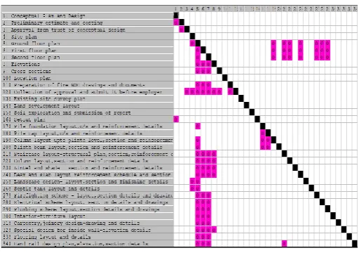
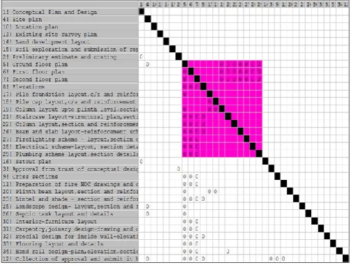
[image:4.595.308.564.239.419.2]The design activities are represented in DSM as shown in fig 4.
© 2018, IRJET | Impact Factor value: 6.171 | ISO 9001:2008 Certified Journal | Page 4942 challenging to organize, often requiring much more time and
many iterations of information transfer. The design phase of any building is principally composed of coupled design tasks. The previous two techniques examined are not sophisticated enough to represent these complex relationships, where information transfer is essential and iteration typical. DSM can represent and analyse the coupling of design tasks and can analyse it. This direct approach requires the design planner to have a detailed understanding of the information requirements of tasks likely to be performed. For a large, complex multidisciplinary process such as building design a detailed appreciation of the information transfers may not be possible. The design process model captures and represents this knowledge in an easily understood form. This is deemed essential to programme the design of a building successfully.
In this DDSM model the list of drawings from the three disciplines- Architect, Structural Engineer, and MEP Engineer were collected. The design drawing details and flow of information among different disciplines during the design phase presented. The relationship between the drawings and each disciplines were obtained and it was modelled in the DDSM model. The inputs are put in rows and feedbacks above diagonals. The relationship between the processes was denoted as “zero” in pink colour in the respective cells. The “PSM 32” software was used to sequence the drawing design - based DSM. There exists interdependency between some drawings. Some drawings have not any information dependency, and some drawings have only dependent relation. The process can be divided into three segments. 1) Developing the floor plans, 2) Developing the structural design of each components in the building, 3) Developing MEP design works.
In fig 5, coloured block represent the inter-related tasks. Every inter-relation is not necessary for executing a process. But sometimes, inter-relations are necessary to achieve higher degree of accuracy for the work. Managing the information flow between each process is a difficult task and their exist complexities with the out-dated technology. The problems associated with each segment need to be studied. 1) Developing the floor plans, Section and Elevation Floor plans can be developed only after accepting the requirements of customer, available land space, conceptual plan, preliminary estimate and costing etc. It should include all the details like Project location, Designer’s name and Building Code Identification Number (BCIN), Scale of drawings, Cross-section symbol, Structural members (joists, beams), including sizes, materials, direction and lengths, Exterior walls, Exterior dimensions, Interior partitions, Interior dimensions, Room sizes and names, Door sizes and locations, Window sizes and locations, Heating appliances, Fireplace or woodstove location, Plumbing fixtures, Bathroom fans, if floor trusses are used, provide engineered drawings and a floor truss certificate. The information from these are transferred to structural engineer and MEP
engineer. But there can be an issue of changes in the design. So, there is a chance of rework on plans based on the requirements of architect, structural engineer and MEP engineer.
2) Developing the structural design of components
[image:5.595.308.560.355.545.2]Structural design consists of design of foundation, column, beam, slab and staircase. In fig 5 , from the coloured block, it represents the interrelationship between architectural drawings and structural drawings. It is essential that design of each component needs the details from plan and section, which means that only after the completion of drawings of plan, elevation and section structural engineers, can proceed their work. Also there can be problems arises while designing regarding the size, shape etc. of beam, column, slab and foundation. So, it needs to revise the plan to accommodate the changes made by structural engineer. It shows that their exists an inter-dependency between architect and structural engineer. While changing the design drawings it will affect the whole work and whole design process. Therefore, careful information exchanges and detailed drawings are necessary in the design process.
Fig – 5: Partitioned DDSM for the Arts College Building 3) Developing MEP design works
© 2018, IRJET | Impact Factor value: 6.171 | ISO 9001:2008 Certified Journal | Page 4943 The relationship between different people disciplines under
[image:6.595.38.295.320.526.2]design process can be represented as shown in fig 6.
Fig - 6 : People DSM for the Building
From fig 6, it reveals that, there is always a strict relationship exists between an Architect, Structural Engineer, MEP Engineer and Client. The work can be executed smoothly only if they have a enough teamwork and proper design. A decision change for any one can affect the whole disciplines and it will affect the whole work.
6. SOLUTIONS FOR MANAGING THE INFORMATION
FLOW DURING DESIGN PHASE
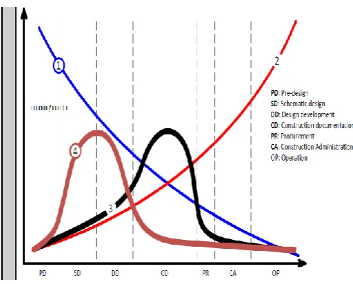
Fig – 7: Boehm Chart for Virtual Construction Flexibility
Cost of Design Changes Actual Construction
Virtual Construction The chart shown in fig 7 expresses the cost and ability to change with respect to different phases of a project. The graph clearly shows that decisions made early in a project (during design) can be made at lower cost and with greater effectiveness. Cost is a measure of the designer’s capacity to make change, the designer’s ability to design. Designers have more capacity to make change on a flexible representation, while at the other end of the spectrum the designer has very little influence on changes. Being able to change the design empowers the designer to explore the solution space, to
reconsider the design problem and to respond when forces outside their control influence the project. While there is a cost associated with changing a design, flexibility aims to lower this cost by making designs more susceptible to change. That is why architects need flexible representations, why architects need parametric models. The curve shown in black colour shows actual construction and the one with brown colour shows virtual construction. Virtual construction shows that the work can be completed without delay and rework during construction stage and any changes can be done during design stage itself. Actual construction shows that rework can occur during construction stage which may cause delay and increase overall cost of project. A reasonable inference from the graph is that projects will benefit by having more diverse expertise in the room during design, so that decisions taken during the design phase is crucial.
In addition to shifting design decision making forward, redefinition of phases is driven by two key concepts: the integration of early input from constructors, installers, fabricators and suppliers as well as from designers; and the ability to model and simulate the project accurately using BIM tools. These two concepts enable the design to be brought to a much higher level of completion before the documentation phase is started. Thus the first three phases of the integrated project: Conceptualization, Criteria Design, and Detailed Design involve more effort than their counterparts in the traditional flow. This higher level of completion in earlier project stages means that the next phase, Implementation Documents, requires less effort than the traditional Construction Documents phase, and the early participation of regulatory agencies, trade contractors, and fabricators allows shortening of the fifth and sixth phases, as well. The result is that the project is defined and coordinated to a much higher level prior to construction start than is typical with traditional delivery methods, enabling a more efficient Construction phase and a potentially shorter construction period.
© 2018, IRJET | Impact Factor value: 6.171 | ISO 9001:2008 Certified Journal | Page 4944 The preliminary work needs to involve the building
owner. Getting the owner involved on early is important so architects can be sure their design meets the client’s standards and avoiding numerous revisions. For this reason, owner input is valuable to designing and planning a cost-effective project. Specifically with MEP integrations, the information generated from the initial MEP analysis provides a realistic cost of the project and the potential changes. Based on the MEP data, the building owner can make final decisions the project's design and build in the early stages, rather than later on in the process when changes are more difficult and costly. By resolving these issues early on, the value of the design increases.
Timing of collaboration - Collaboration between architects and engineers, “earlier is better”! This is especially true at the conceptual stage of a project where critical project-shaping decisions can be made easily, compared to being much more difficult, costly, and inefficient later in the project. The need for collaboration at all stages, from conceptual design through to construction, has implications when one professional is preparing an agreement for other consultant services. For example, after obtaining the client’s approval, an architect preparing this agreement should make special provision to obtain the conceptual design advice the project deserves. More complex projects require higher degrees of engineering expertise. Establishing a cohesive project team right from the beginning is essential.
Building Information Modeling (BIM) - BIM systems are becoming more widespread and facilitate collaboration when a single BIM model is used by all members of the design team. BIM has two attributes. The first is the geometry or 3D object and second is the associated data of the object, like the manufacturer specifications, size, and location. Together, they form smart objects that are "parametric" in nature. So if the data changes, the geometry changes with it and vice versa.
Initiate collaboration as early as possible by engaging structural and other engineers at the pre-design/concept design stage for the best project outcome.
Match an engineer’s expertise and experience with the complexity of the project. When leading a design team, cultivate an open and trusting culture to facilitate knowledge sharing, and encourage a ‘best for the project’ consensus approach.
Facilitate communication with and between design team members so that all contribute fully and are
satisfied with and take responsibility for the solutions at each design stage of the project. Increase understanding of structural and
non-structural seismic design issues.
6. CONCLUSIONS
A two-way exchange of information among design disciplines is common for all construction projects during each and every stages of a project, especially during the design phase of a project. Without bidirectional exchange of information no works can execute smoothly without any delay. Currently there is no management tool to model bidirectional exchange of information among the activities in a project. Although there exists some tools, but they have their own limitations when the projects get into bigger. Since they are in graphical form. To address this issue, a matrix-based tool called the Design Structure Matrix (DSM) has evolved. This method differs from traditional project-management tools because it focuses on representing information flows rather than work flows. The matrix indicates groups of tasks that are interdependent and therefore require careful co-ordination. They identify iterative cycles and assumptions that need to be made. They also suggest proper sequence of design decisions and provide insights into the concurrency in the processes. DSM method enabled the representation of the processes studied in the case study in a compact form.
From the model obtained using DDSM the problems and issues during the design phases were identified and solutions for them were discussed here. As drawings are well-defined entities that are directly identifiable by the design team, here proposes drawing DSM (DDSM) to manage the design process [13]. The solutions for minimizing the difficulties arising during the design process are also discussed here.
REFERENCES
[1] Austin . S , Baldwin . A and Newton. A. (2007) “A Data Flow Model to Plan and Manage the Building Design Process “. Journal of Engineering Design, pp. 3-25.
[2] Austin .S., Baldwin . A., Li B. and Waskett .P. (2000).”Analytical Design Planning Technique a Dependency Structure Matrix Tool to Schedule the Building Design Process”. Construction Management and Economics, pp. 173-182.
© 2018, IRJET | Impact Factor value: 6.171 | ISO 9001:2008 Certified Journal | Page 4945 [5] Browning .T.R. (2001).”Applying the Design Structure
Matrix to System Decomposition and Integration Problems”. IEEE Transactions on Engineering Management ,48 (3), pp. 292-306.
[6] Browning .T. R. (1998) “ use of Dependency Structure Matrices for Product Development Cycle Time Reduction ”. International Conference on Concurrent Engineering. [7] Chen C.H., Ling S.F.,Chen W. (2003). “Project Scheduling for Collaborative Product Development Using DSM”. International Journal of Project Management, pp. 291-299. [8] S. D. Eppinger, D. E. Whitney, R. P. Smith and D. A. Gebala “A Model-Based Method for Organizing Tasks in Product Development “. Massachusetts Institute of Technology. [9] Jacob. J. ,Varghese, K. (2012).”A Model for Product – Process Integration in the Building Industry Using Industry Foundation Classes and Design”. International Dependency and Structure Modelling Conference.
[10] J.U. Maheswari , K. Varghese and T. Sridharan (2006) “Application of Dependency Structure Matrix for Activity Sequencing in Concurrent Engineering Projects ”. Journal of Construction Engineering and Management, pp. 482-490. [11] A. A. Oloufa , Y. A. Hosni , M. Fayez and P. Axelsson (2007) “Using DSM for modeling information flow in construction design projects”. Civil Engineering and Environmental Systems.
[12] Pektas.S.T. (2005). “Modelling Detailed Information Flows in Building Design with the Parameter-based Design Structure Matrix”. International Dependency and Structure Modelling Conference, pp. 99-122.
[13] Senthilkumar V. and Varghese K. (2013). “ Structured Methodology to Formulate Drawing Dependency Structure Matrix for Construction Design ”. Architectural Engineering and Design Management, pp. 225-248.
[14] Seyed M.M (2016). “Application of DSM for Integrating Modern Technology into Operational Architecture of Aerial Firefighting”. International Dependency and Structure Modelling Conference.