Journal of Chemical and Pharmaceutical Research, 2014, 6(6):2497-2503
Research Article
ISSN : 0975-7384
CODEN(USA) : JCPRC5
Design of electrical meter reading system based on CDMA network
Yan Yang
Energy and Electrical Engineering Institute, Nanjing Institute of Industry Technology, Nanjing, China
_____________________________________________________________________________________________
ABSTRACT
This paper presents a new means of communication for remote meter reading system which uses CDMA data service. The system has made good use of CDMA features like permanent being online, timely transmitting, and charging based on traffic rather than time. Using CDMA technology for remote meter reading system will not only greatly improve stability, reliability and timeliness of the system, but also significantly reduce the costs of the system operating. To ensure the safety and integrity of the energy consumption data, we proposed a new protocol that composed by dynamic authorization component and encryption component. The system uses a CDMA module named MSP430F149 to login into the CDMA network, which enable the system to transmit data wirelessly..
Key words: CDMA, Meter, electric energy
_____________________________________________________________________________________________
INTRODUCTION
With the rapid development of science and technology, electricity is playing a more and more important role in daily life and social development. However, the traditional meter reading method cannot meet the needs of power management for its low accuracy, besides it cannot afford timely data for many applications. For the electricity supply utility, manual meter reading method has already been a major challenge with many shortcomings such as difficulty of entering households, high labor cost, and strong possibility of man-made mistakes. In China, Meter reading system is faced with great difficulty, such as too many data collection points, large amount of data and extremely decentralized distribution of meter. Together with the rapid development of communicating technology, computer network technology and digital signal processing technology, there comes a variety of automated meter reading technology. Automatic Meter Reading-AMR refers to automatic meter reading and data processing that collects data from meters via communication and computer technology remotely. Automatic meter reading technology can not only save human resource, more important, it can also improve the accuracy of the data, allow electricity management departments to get timely and accurate data, forecast the load of the power grid and control the power consumption before it is too late, which may benefit overall industry.
Automatic Meter Reading System
It is known to all that with the development of the so-called smart grid, electrical meter reading system has been widely used throughout the country. Electrical meter reading system can autonomously collect the consumption and status data from electric meters, and deliver the data to the utility providers for billing or analysis purpose. The concept of automatic reading system dates back to 1960s. Usually, electrical meter reading system has three main components: (1) AMR (automatic meter reading) meter that can collect consumption data and transmit it through RS-485 bus, and (2) collectors that can receive consumption data from the meter and send it to the data center, and (3) the data center that can receive data and analyze it. Usually, AMR meters measure the total consumption of electricity, gas, or water. Regardless of what meters are measuring, their core components remain the same. Each automatic meter is comprised of a meter engine and an encoder-receiver-transmitter. The meter engine measures the consumption through a mechanical dial that rotates at a speed proportional to the amount of consumption. With the help of electromechanical or electro-optical interfaces, the movements of dials are converted to digitals [5]. Different meters have different appearance, communication protocols and power supplies depend on what they measures. Electric meters are usually powered by the main electricity supply lines, while others may be battery [11-14].
Contributions
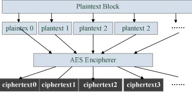
Broadcast of fine-grained energy data through secure protocol: As it’s known to all, the data sent to the data center is to be used for analysis for many purposes, so we need to keep an appropriate frequency for data collection. The collector of the meter reading system we proposed continuously broadcasts its energy consumption through CDMA wireless network every 15 minutes. However, researches have shown that fine-grained energy consumption can reveal sensitive personal information of smart from homes [6-8]. To ensure the safety of the energy data, we transmit the data through special protocol that use the AES algorithm to encrypt the data packages, which is strong and fast enough for our system.
Dynamic authorization protocol to ensure the integrity of data: As it is mentioned before, data collected from the meters would be analyzed for different purposes. If someone gets the ID of the collector and sends fake data to the data center, there will be a disaster in the whole system. To avoid fake data, we propose a dynamic authorization protocol in this paper, which will ensure the integrity of the data uploaded from the collectors. We utilize a secret sequence to identify every collector, rather than the ID. Besides, the data center will dynamically generate random sequence, which is to be used as a kind of token, before receiving any data. If the target collector returns wrong hash value, then the data center will refuse receiving data from that collector, which will be regarded as a fake collector. This dynamic authorization protocol is simple but efficient.
Transmit data through CDMA wireless network: We here present a new means of communication for remote meter reading system that takes advantages of the CDMA network service. With the help of the CDMA wireless technology, the system can acquire a rather low cost of deployment and a great convenience in management. Besides, the system can be applied almost in everywhere as it doesn’t need more equipment than a CDMA module for its data transmission. Experiments have shown that, our system can be widely used in every corner in the country with a high speed of data transmission and low extra power consumption.
ERROR CORRECTION THEORY OF TOTAL ENERGY CONSUMPTION
OVERALL SOLUTION DESIGN
All Power Bureau (Power Company or electrical company) should manage the power consuming and regional distribution within its jurisdiction. Generally, meter reading can be divided into 3 categories: large users, residents and substations. The whole meter reading system includes both hardware and software. Hardware client can be divided into different types: Substation terminal, residents terminal, negative control terminal (large users) etc. CDMA terminal use CDMA for transmission, with built-in GRPS Communication Module. In addition to the general meter-reading functions, CDMA terminals also have some other monitoring functions, such as anti-tamper, load control, etc. Software of this system consists of three major components: meter reading host, data collection terminal with CDMA module and the power meter. In some relatively backward areas, funds to build reading system is not enough, most of the time, several different applications are running on the same server. Generally these areas lack adequate funding for special network construction, reading system often run directly on the public network. System architecture design must take full account of the actual situation of the scene, at least to meet the following requirements.
Network architecture should not only be able to support VPN, but also to support the public network in Internet mode.
Meet the needs of users with dedicated access line, and also need to consider the users without fixed IP, accessing internet with dynamically assigned IP. Support multiple client programs running simultaneously.
Meet the needs of special situation like user must conduct terminal management, but he can not access the Internet. While conducting simultaneous control of multi-client multi-terminal, control CDMA traffic to the minimum, to achieve the purpose of cost savings to users.
Meter host (data receiving control unit), computer (server or PC) running meter reading system is called as meter reading host. Host connects to collector through CDMA network. Master station need to be configured with a fixed IP address and Internet export. Collection terminal with CDMA module (meter reading unit): receive meter data and send to the data center, it connects the host meter and energy meter. Energy meter (Terminal Data Unit): Measure and display the user's electricity consumption, electricity consumption information will be transmitted to the collector.
Figure 1. Overall system diagram
We use 32-bit ARM processor, internal control software development according to standard C, with driver layer and business logic layer. The main idea is: driver layer encapsulates the underlying operating of the hardware; the business logic layer calls the driver to complete the implementation of instructions. For the hardware platform changing or upgrading, the only need is to upgrade driver layer without changing the logic layer, thus greatly simplified hardware platform migration workload.
HARDWARE STRUCTURE OF DATA COLLECTION TERMINAL
Figure 2. Data collection terminal hardware structure
MC35i module is a new generation of GSM / CDMA dual-mode module produced by Siemens. It is compatible with the MC35, with lower power consumption, and provides users easier access to mobile data communication. MC35i has compact design, with TCP / IP protocol processing function, and supports both sending and receiving of SMS and CDMA wireless data transfer mode, it's the main communication module of the system.
Data input and output interface of MC35i is actually a serial asynchronous receiver transmitter (UART). Consistent with ITU-TRS-232 interface standard, it has fixed parameters: 8 data bits, l stop bit, no parity. Baud rate is selectable between 300bps-230400bps. Hardware communication signals are RTS0/CTS0, XON / XOFF, which control flow via software AT commands. AT command to MC35i can be written via UART to realize the control, at the same time a variety of status information will be replied to user in AT commands form through UART. AT commands can be considered as the interface language between users and terminal equipment.
System can support a variety means of communication, which can be divided into CDMA, UDP, SMS, serial port, infrared, LAN (using MXOA card) and many other methods. Software supports 3 types of channel modes and communication parameters. Main channel comes first, if the main channel failed, then it selects the sub-channel, initial channel parameters set by the infrared Pocket PC, after configuration, system may initialize all channel parameters. At this point, the master host computer can choose a way to communication. There is only one upload port in ARM chip (U0 port), so that the program will be at different types of channel status in different time.
MC35i module circuit design
Power circuit, MC35i uses single 3.3V to 4.8V power supply, as MC35i may reach 2A current peak during the course of data transmission, the power must be able to provide enough current to ensure that the high current power supply voltage is not less than 3.3V. While it's working, if the voltage drops below 3.3V or drops more than 400mV, MC35i will automatically turn off. E.g. when it arrive the 2A peak current, the voltage loss on the line must be considered, if the line resistance is 50mΩ, then the voltage loss is 100mV, such issue must be considered during wiring. When the module is closed, it needs external supply voltage; the range is 2.0V to 5.5V.
logical page number. Reading data during a certain time may reduce the task in half.
The communication interface circuit of MSP430F149 microcontroller
Communication interface circuit which is connected to two serial ports of MSP430F149 respectively consists of two parts. One connects to power meter through MAX485 and RS-485, which is responsible for collecting meter data, and to issue the corresponding order in accordance with relevant agreements to collect the corresponding data on the meter. Another connects to CDMA through MAX3232 and RS-232 standard interface, which is to achieve the control of the CDMA module, to transmit collect data from the CDMA module to the CDMA network, and finally to realize the communication with the meter reading host. The connection to target server via TCP/IP protocol identify the status of CDMA. If it is not online, it will check the CDMA signal strength and re-connected intervals, re-connect to the server at the right time, and send login packet to server program after successful connection to server.
COMMUNICATION PROGRAM DESIGN Configurations before data transmit
Before accessing Internet by CDMA, we must first set the configuration of module. The main configurations include such steps below.
Set communication baud rate, you can use AT + IPR = 38400 command, set baud rate to 38 400b / s or other appropriate baud rate, the default communication speed is of 9600b / s.
Set the gateway access, set the CDMA access to Monternet through AT + CGD CONT = 1, "IP", "CMNET" command.
Set the type of mobile terminal, and set the type for the mobile terminal through the AT + CGCLASS = "B", that means monitoring a variety of business at the same time. But it can only run one business, that is only using CDMA to surf the Internet or using GSM voice communication during the same time.
Test whether the CDMA service is on. Use the AT + CGACT = 1,1 command to activate the CDMA features. If it returns OK, then the CDMA connection is successful; If the return is ERROR, it means that CDMA connection is failed.
At this time, we should check whether the SIM card of the CDMA business is in service, as well as whether CDMA module such as the antenna is installed correctly. After completion of the initialization CDMA module, you can dial-up to achieve CDMA connection. Dial-up process flow chart shown in Fig. 3.
Figure 3. Dial-up process flow chart
Dynamic authorization protocol
it is right or not when it receives the hash value. If the hash value is right, then the data center will receive the data the collector upload, otherwise, it will refuse to receive the later data. This protocol is simple but efficient to ensure the integrity of the data collected from the meters. Fig.4 shows the detail of this protocol.
Figure 4. Detail of the dynamic authorization protocol
The detail of the protocol can be described as below.
The collector sends a request to the data center to upload data. The request package data includes the ID of the collector, which can identify the collector. Besides, the package also includes some other information such as the time when the package is sent.
The data center will check the ID in the request package that whether it is in the ID data base. If the ID is in the data base, then the data center will send a random sequence of 128 bits generated by a special program that can ensure the randomness of the sequence. Same with the request package, the package that the data center sends back includes a time stamp.
The collector links the sequence received from the data center with its own identity sequence. Then the collector uses a digest algorithm to get the digest of the new sequence. In this protocol, we use the SHA-1 algorithm to get the digest of the sequence. The collector will send the digest to the data center before it sends energy data package.
The data center will check the digest received from the collector whether it is right or not. If the digest matches the value in the data base, the data center will send a package that includes pass information to the collector and get ready to receive data package from the collector. Otherwise, the data center will refuse to receive any package from the collector again.
Encrypt algorithm
[image:6.595.206.401.560.654.2]system. Compared to other physical line communications, it has unparalleled advantages. With the gradual improvement of CDMA networks and application technology, CDMA will be applied in more areas. The CDMA wireless transmission system described in this article can be applied to a variety of industries such as finance, water supply, environmental protection, gas, transportation and so on. But the system’s actual situation is complex; the performance of the system is not perfect. Such as data center applications need further development to check and analyze various types of data to increase the automation of power management.
REFERENCES
[1]Liu Xiao-lan. China Sport Science and Technology. 1984, 29(13), 46-49.
[2]Luo Yang-chun. Journal of Shanghai Physical Education Institute. 1994, 23(12), 46-47. [3]Wan Hua-zhe. journal Of Nanchang Junior College. 2010, 3, 154-156.
[4]Li Ke. Journal of Shenyang Sport University. 2012, 31(2), 111-113.
[5]Zhang Shu-xue. Journal of Nanjing Institute of Physical Education. 1995, 31(2), 25-27. [6]Pan Li. Journal of nanjing institute of physical education(natural science). 2004, 19(1), 54-55. [7]Li Yu-he; Ling Wen-tao. Journal of Guangzhou Physical Education Institute. 1997, 17(3), 27-31. [8] Xu Guo-qin. Journal Of Hebei Institute Of Physical Education. 2008, 22(2), 70-72.
[9] Chen Qing-hong. China Sport Science and Technology. 1990, 21(10), 63-65
[10] Tian Jun-ning. Journal of Nanjing Institute of Physical Education. 2000, 14(4), 149-150.