International Journal of Emerging Technology and Advanced Engineering
Website: www.ijetae.com (ISSN 2250-2459, ISO 9001:2008 Certified Journal, Volume 3, Issue 5, May 2013)
197
Method of Improving Voltage Quality Using Modern Power
Electronics
Ashish Srivastava
1, Ravi Dixit
2, Ashish Kumar Pandey
31
Sr. Lecturer MPEC Kanpur
2Asst. Professor RIET Kanpur 3Asst. Professor PSIT Kanpur
Abstract-- This paper presents a comprehensive simulation study of PI Controlled Three phase Series active power filter to improve power quality. The series active power filter employs a method for the reference compensation current based on Fast Fourier Transform Passive, L-C filters have disadvantage of fixed compensation and not fit for fast varying condition while by using auto tuned active power filter gives better results for reactive power compensation and power factor improvement and compels to limit the THD well within the acceptable range as mentioned in IEEE-519 standard. MATLAB Model and simulated results are presented to verify the proposed control techniques.
IndexTerms-- Power quality, UPQC, Harmonics,
Non-Linear load, Series Active filter, Hysteresis controller, MATLAB, SIMULINK.
I. INTRODUCTION
Recently, the use of semiconductor switching equipment, such as diodes and thyristors rectifiers, has sharply increased. Power quality degradation generally results from these and other non-linear loads. The more non-linear loads increase, the more complex steps are required to avoid power quality degradation, such as harmonic increase, power factor degradation etc. Passive filters have traditionally been used to eliminate harmonic currents, which are generated by nonlinear loads. To eliminate the harmonics in broadband, too many passive filters would be required. In addition, the hazard of resonance with the source impedance would become quite difficult to avoid. Studies on active power filters began in the late 1970s to overcome the defects of the passive filter. The active power filter is more expensive than the passive, but the former has an advantage in that it can simultaneously eliminate the broadband harmonic at the source stage. Active power filters are categorized as follows: the parallel active power filter, which injects compensation currents; the series active power filter, which injects compensation voltages through a transformer; and the combined system of parallel passive filters and series active power filter.
Generally, if the DC smoothing inductor is sufficiently large, nearly constant DC current flows in the DC link of a rectifier. So this type of load can be called a harmonic current source. The parallel active power filter is suitable for compensating for these harmonic current sources, while the series active power filter is appropriate for compensating for the harmonic voltage source, which has sufficient capacitance component in the DC link of the rectifier. In particular, the solution for a harmonic voltage source is critical because the loads that act as harmonic voltage sources, such as copiers, fax machines, fluorescent lamps, air conditioners etc., have continued to increase. In this chapter, the proposed control algorithm for series active power filters is applicable to harmonic voltage source loads as well as to harmonic current source loads. This control algorithm is applied under the basic concept of the generalized p–q theory. However, this generalized p–q theory is valid for compensating for the harmonics and reactive power using the parallel active power filter in the three-phase power system. To overcome such limits, a revised p–q theory is proposed. This revised algorithm may be effective not only for the three-phase three-wire series active power filter with harmonic current voltage loads, but also for the combined system of parallel passive filters and active filter. Another drawback of the generalized p–q theory is that the compensation voltage will be determined by multiplying the gain, which is dependent on the value of current. To obtain the current, some computational efforts are needed using the instantaneous real power and imaginary power. The proposed control algorithm directly extracts compensation voltage references without multiplying the gain. Therefore, the calculation of the compensation voltage reference will turn out to be simpler than for other control algorithms.
A.Basic compensation principle
International Journal of Emerging Technology and Advanced Engineering
Website: www.ijetae.com (ISSN 2250-2459, ISO 9001:2008 Certified Journal, Volume 3, Issue 5, May 2013)
198
This is controlled so as to draw or inject a compensating voltage Vc from or to the supply, such that it cancels
voltage harmonics on the load side i.e. this active power filter (APF) generates the distortions opposite to the supply harmonics. Fig 1.1 (b) shows the different waveforms i.e. source voltage, desired load voltage and the compensating voltage injected by the series active power filter which contains all the harmonics, to make the load voltage purely sinusoidal. This is the basic principle of series active power filter to eliminate the supply voltage harmonics.
Fig 1.1 (a) Basic compensation principle
Fig 1.1 (b) Waveforms for the supply voltage,Desired load voltage and the Compensating voltage (filter voltage)
B.Estimation of Reference Voltage
This Section introduces the control algorithm of the series active power filter, which compensates for harmonics and reactive power. The three-phase voltages va,
vb and vc and currents ia, ib and ic for the phase
[image:2.612.332.558.146.295.2]three-wire power distribution system is shown in Fig. 1.2.
Fig 1.2 Circuit configuration for series active power filter
The three-phase load voltages vL(a,b,c) and the three-phase
source currents is(a,b,c) are represented as:
, (1.1)
The load voltage vector vL(a,b,c) and the source current
vector is(a,b,c) of (1.1) are transformed into
co-ordinates by the substituting (1.3) into (1.2) as
,
= (1.2)
(1.3)
The active power p can be expressed as (1.4) by the inner product of the load voltage vector VL(α,β,0) and the
source current vector is(α,β,0) of (1.2), where the active
[image:2.612.71.265.258.542.2] [image:2.612.325.505.433.582.2]International Journal of Emerging Technology and Advanced Engineering
Website: www.ijetae.com (ISSN 2250-2459, ISO 9001:2008 Certified Journal, Volume 3, Issue 5, May 2013)
199
p = = (1.4)
Also, the reactive power qL(α,β,0) is represented as (1.5)
by the cross product of VL(α,β,0) and is(α,β,0)
(1.5)
q = = (1.6)
Where, q is the instantaneous reactive power at the load side of the CT in Fig.1.2.
For a three-phase system without zero sequence voltage and current, i.e Va+Vb+Vc=0, and ia+ib+ic=0.
and,
. Equations (1.4) and (1.5) can
be expressed as follows:
p = = (1.7) =
(1.8)
From (1.1)–(1.5), the active voltage vector
v
p (α, β, 0)andthe reactive voltage vector
v
q (α, β, 0)are defined as follows:= (1.9)
= (1.10)
The active voltage vector and the reactive voltage vector can be obtained by the vector norm of the three-phase load voltage vector, which is known from (1.9), (1.10). In other words, represents the parallel component of the load voltage vector to the current vector ; represents the perpendicular component of the load voltage vector to the current vector .
As a result, the load voltage vector is represented by the sum of the active voltage vector and the reactive voltage vector as follows:
= + (1.11)
The active voltage vector
v
p(α, β, 0)is induced as follows,using the projection of the load voltage vector onto the current vector :
= proji =
=
= (1.12)
The reactive voltage vector , which is perpendicular to the active voltage vector , is also induced through (1.13)–(1.16):
= =
(1.13)
(1.14)
(1.15)
After taking a cross product on both sides of (1.13), (1.14) is obtained when the right side of (1.13) is unfolded by means of the relations of inner and cross product. After transposing the current vector component of the right-hand side to the left side in (1.14), (1.15) can be obtained. The second term of the right-hand side of (1.15) is the active voltage vector and the first term of the right-hand side of (1.15) becomes the reactive voltage vector :
International Journal of Emerging Technology and Advanced Engineering
Website: www.ijetae.com (ISSN 2250-2459, ISO 9001:2008 Certified Journal, Volume 3, Issue 5, May 2013)
200
Where is equal to the reactive power, which is defined in the instantaneous reactive power theory. The voltage compensation reference of the series active power filter can be represented as (1.17), using and
in (1.9) and (1.10).
(1.17)
The active power and the reactive power can be divided into DC components and , which are generated from the fundamental components of the load voltages and the source currents, and AC components and , which are generated from the negative sequence components and the harmonic components of the load voltages and the source currents. If the reactive power q is replaced by the AC component of reactive power , a new voltage compensation reference compensates for the AC component of the active power and the reactive power .
The compensation voltage reference in co-ordinates is obtained from (1.17) and the final compensation voltage reference by transforming this compensation voltage reference in co-ordinates into the compensation voltage reference of three-phase co-ordinates. Equation (1.19) is the three-phase transformation matrix:
(1.18)
= (1.19)
The entire algorithm can be explained as: First, three-phase load voltages and source currents are transformed into co-ordinates. Then, the active power and the reactive power can be calculated. The AC component of the active power is extracted by simple filtering. The compensation voltage reference in coordinates is calculated by substituting the obtained AC component of the active power, the reactive power and the three-phase currents into (1.17).
The final voltage compensation reference for the harmonics and the power factor compensation are obtained by transforming the voltage compensation reference in co-ordinates into the voltage compensation reference in three-phase co-ordinates.
II. CONTROL SCHEME
The control scheme mainly comprises three phase sine wave generator and the generation of switching signals.
First the peak value of the fundamental component of the supply voltage is multiplied by the unit sine vectors in phase with the source voltages to obtain the reference voltages. Three phase reference voltages templates can be generated by using only sine wave generator for generating a sinusoidal signal of unity amplitude, and in phase of mains voltages or it can be generated using the PLL circuits. In this way the desired reference voltages can be obtained which is balanced and sinusoidal, irrespective of the distorted mains. These estimated reference voltages and the sensed actual load voltages are given to a hysteresis controller to generate the switching signals for the inverter. The difference of the reference voltages and the actual voltages decides the operation or the switches. To increase the voltages of a particular phase the lower switch of the inverter of that particular phase is turned on while to decrease the voltage the upper switch of the respective phase is turned on. A lockout delay can be given between the switching of the upper and the lower device to avoid the shoot through problem. These switching signals after proper isolation and amplification should be given to the switching devices. Due to these switching actions a voltage is injected through the series transformers to compensate the harmonic voltage so that only sinusoidal voltage is available to the load.
III. MATLAB SIMULINK MODEL
International Journal of Emerging Technology and Advanced Engineering
Website: www.ijetae.com (ISSN 2250-2459, ISO 9001:2008 Certified Journal, Volume 3, Issue 5, May 2013)
201
The output of the series active power filter is fed to the main lines through series transformers so as to make the load voltage purely sinusoidal the harmonic voltage is absorbed or injected by the filter.
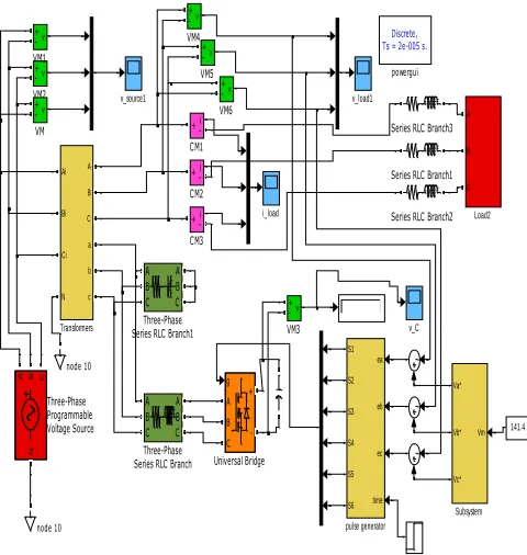
v_source1 v_load1 v_C ea eb ec time S1 S2 S3 S4 S5 S6 pulse generator Discrete, Ts = 2e-005 s.
powergui i_load v + -VM6 v + -VM5 v + -VM4 v + -VM3 v + -VM2 v + -VM1 v + -VM g A B C + -Universal Bridge A B C a b c Ai Bi Ci N Transformers A B C A B C Three-Phase Series RLC Branch1
A B C A B C Three-Phase Series RLC Branch
N
A B C
Three-Phase Programmable
Voltage Source Vm
Va*
Vb*
Vc*
Subsystem Series RLC Branch3
Series RLC Branch2 Series RLC Branch1
[image:5.612.336.549.133.347.2]node 10 node 10 A B C Load2 141.4 i + -CM3 i + -CM2 i + -CM1
Fig 1.5.1 MATLAB model for Series active power filter
Fig 1.5.1 (a) Reference voltage generation
Fig 1.5.1 (b) Pulse generation diagram
IV. RESULT
[image:5.612.50.290.192.445.2]Figure 1.5.2 shows the three phase voltage having harmonic contents in it thus it is the source voltage to Series Active Power Filter
Fig 1.5.2 Source voltage containing harmonics
[image:5.612.328.559.418.503.2]The Figure 1.5.3 shows the load voltage before and after compensation by the series APF, As the pulse is generated at 0.1 seconds, harmonic content in the load voltage reduces considerably
Fig 1.5.3 Load voltage before and after compensation
[image:5.612.63.274.475.657.2] [image:5.612.328.560.562.636.2]International Journal of Emerging Technology and Advanced Engineering
Website: www.ijetae.com (ISSN 2250-2459, ISO 9001:2008 Certified Journal, Volume 3, Issue 5, May 2013)
[image:6.612.59.280.132.214.2]202
Fig 1.5.4 Load current
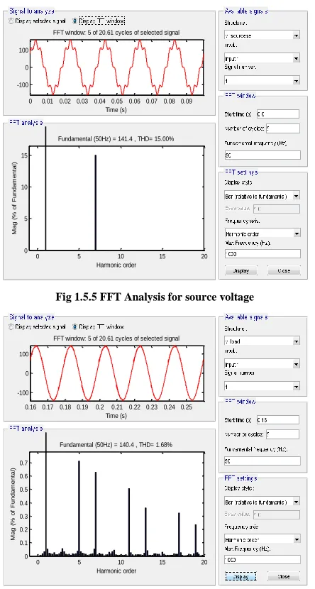
The figure 1.5.5 and fig 1.5.6 shows the Fast Fourier Transform (FFT) analysis of the source voltage and the load voltage of the Series Active Power Filter respectively. The FFT Analysis of the voltages also shows that the THD is reduced up to a very large extent hence improving the performance of the system
0 0.01 0.02 0.03 0.04 0.05 0.06 0.07 0.08 0.09 -100
0 100
FFT window: 5 of 20.61 cycles of selected signal
Time (s)
0 5 10 15 20
0 5 10 15
Harmonic order Fundamental (50Hz) = 141.4 , THD= 15.00%
M
a
g
(
%
o
f
F
u
n
d
a
m
e
n
ta
[image:6.612.325.562.234.710.2]l)
Fig 1.5.5 FFT Analysis for source voltage
0.16 0.17 0.18 0.19 0.2 0.21 0.22 0.23 0.24 0.25 -100
0 100
FFT window: 5 of 20.61 cycles of selected signal
Time (s)
0 5 10 15 20
0 0.1 0.2 0.3 0.4 0.5 0.6 0.7
Harmonic order Fundamental (50Hz) = 140.4 , THD= 1.68%
M
a
g
(
%
o
f
F
u
n
d
a
m
e
n
ta
l)
Fig 1.5.6 FFT Analysis for load voltage
V. CONCLUSION
In this paper the basic compensation principle, the estimation of reference voltage and the modeling of series APF have been discussed in detail. Also the hysteresis control scheme used for controlling the series active power filter has been discussed in this paper.
TABLE I
THD analysis for different loads, for series active power filter
VI. APPENDIX
The values of the different parameters used for series active power filter
Source voltage: 3-phase, 100V, 50Hz.
Harmonics in the supply voltage:
5th, 0.2pu and 7th, 0.15pu.
Series transformer rating: 1kV, 50Hz, 240/24V
RL load parameters : 10 Ω, 100mH
DC machine load: 240V field voltage,
Rf =240 Ω, Ra = 0.5 Ω, 50Hz.
Line parameters : 0.2 Ω, 1.5mH
Line parameters : 0.2 Ω, 1.5mH
RC filter parameters : 16 Ω, 199.04μF
Hysteresis band gap : -0.01 to 0.01
REFERENCES
[1] R Virmani , P. Gaur, H. Santosi , A.P. Mittal and B. Singh; “
Performance Comparison of UPQC and Active Power Filters for a Non-Linear Load”; International Conference on Power Electronics, Drives and Energy System, pages: 1-8.
[2] Guozhu Chen, Yang Chen, Luis Felipe Sanchez, and Keyue M.
Smedley, “Unified Power Quality Conditioner for Distribution System without Reference Calculations”, paper IEEE 2000.
[3] M Vilathgamuwa, Y H Zhang., S.S.Choi; “Modeling, Analysis and
Control of Unified Power Quality Conditioner”; 8th International Conference on Harmonics and Quality of Power ICHQP '98, by IEEE/PES and NTUA, October I4-16, 1998, pages: 1035-1040.
[4] Fang Zheng Peng, Hirofumi Akagi and Akira Nabae, “Compensation
Characteristics of the Combined System of Shunt Passive and Series Active Filters”, IEEE transactions on industry applications, vol.
Load type THD (%) source
voltage
THD (%) load voltage
[image:6.612.59.281.291.706.2]International Journal of Emerging Technology and Advanced Engineering
Website: www.ijetae.com (ISSN 2250-2459, ISO 9001:2008 Certified Journal, Volume 3, Issue 5, May 2013)
203
29, No. 1, January/February 1993, pages: 144-152.
[5] Dušan Graovac, Vladimir Kati, Alfred Rufer, Jovan Kneevi,
“Unified Power Quality Conditioner Based on Current Source Converter Topology”, EPE 2001 – Graz, P1-P9.
[6] L.H. Tey, P.L.So, Y.C.Chu, “Unified Power Quality Conditioner for
Improving Power Quality Using ANN with Hysteresis Control”, International conference on power system- POWERCON 2004, 21-24 November 2004, pages: 1441-1446.
[7] “Power and Energy Magazine,” IEEE vol. 1, issue 5,
September/October 2003, pp. 33-38.
[8] Hideaki Fujita and Hirofumi Akagi, “The Unified Power Quality
Conditioner: The Integration of Series and Shunt Active Filters,” IEEE Transaction on Power Electronics, vol.13, no. 2, pp. 494-501, March 1998.
[9] http://www. power-solutions.com
[10] “Performance investigations of shunt active power filter” Ph.d
Thesis by Shailendra Kumar Jain, april 2003 Indian Institute of Technology, Roorkee, guided by Prof. H.O. Gupta and Prof. Pramod Agarwal.
[11] Peng, F.Z.; “Harmonic sources and filtering approaches”
IndustryApplications Magazine, IEEE, vol. 7, issue: 4, July-Aug. 2001 pp. 18 – 25.
[12] Chang, G.W.; Tai-Chang Shee; “A novel reference compensation
current strategy for shunt active power filter control,” IEEE Transactions on Power Delivery, vol. 19, Issue 4, pp. 1751 – 1758, Oct. 2004.
[13] Massoud, A.M.; Finney, S.J.; Williams, B.W.; “Practical issues of
three-phase, three-wire, voltage source inverter-based shunt active power filters,” in proc. of 11th International Conference on Harmonics and Quality of Power,2004. pp. 436 – 441.
[14] Fang Zheng Peng; “Application issues of active power filters” IEEE
Industry Applications Magazine, vol. 4, issue: 5, Sept.-Oct. 1998, pp. 21 – 30.
[15] Routimo, M.; Salo, M.; Tuusa, H.; “A novel simple prediction based
current reference generation method for active power filters,” In proc. of IEEE 35th Annual Power Electronics Specialists Conference, PESC 04,vol.4, pp. 3215 – 3220.
[16] Jain, S.K.; Agarwal, P.; Gupta, H.O.; “A control algorithm for
compensation of customer-generated harmonics and reactive power,” IEEE Transactions on Power Delivery, vol. 19, issue: 1, pp. 357 – 366, Jan. 2004.
[17] Fang Zheng Peng; Ott, G.W.; Adams, D.J.; “Harmonic and reactive
power compensation based on the generalized instantaneous reactive power theory for 3-phase 4-wire systems,” in proc. of 28th Annual IEEE Power Electronics Specialists Conference, 1997. PESC „97, vol. 2, 22-27 June 1997, pp. 1089 – 1095.
[18] Yo-Chan Son; Seung-Ki Sul; “Generalization of active filters for
EMI reduction and harmonics compensation,” in proc. of 38th IAS Annual Industry Applications Conference, 2003. Vol. 2 , 12-16 Oct. 2003 pp. 1209 – 1214.
[19] V. Khadkikar, P. Agarwal, A. Chandra, A.O. Barry and T.D.
Nguyen; “A Simple New Control Technique For Unified Power Quality Conditioner (UPQC),” in proc. of 11th International Conference on Harmonics and Quality of Power-2004, pp. 289-293.
[20] WeiMinWu, LiQing Tong, MingYue Li, Z.M.Qian, ZhengYu Lu,