Materials Science and Engineering Publications
Materials Science and Engineering
9-1998
A new method for strengthening gold
Alan M. Russell
Iowa State University, [email protected]
Kai Xu
Iowa State University
L. Scott Chumbley
Iowa State University, [email protected]
James Parks
Iowa State UniversityJoel Harringa
Iowa State UniversityFollow this and additional works at:
http://lib.dr.iastate.edu/mse_pubs
Part of the
Metallurgy Commons
The complete bibliographic information for this item can be found at
http://lib.dr.iastate.edu/
mse_pubs/147
. For information on how to cite this item, please visit
http://lib.dr.iastate.edu/
howtocite.html
.
A new method for strengthening gold
Abstract
Metal-metal composites were first produced in a copper matrix in the 1970’s, and they have since been
produced in several other binary metal systems. This strengthening technique reinforces a ductile metal matrix
with a ductile metal second phase. In some binary systems, this technique confers extraordinarily high
strength and hardness while still maintaining low electrical resistivity. This article reports on the first gold
matrix metal-metal composite, which was produced by deformation processing a 90%Au-10%Ag powder
compact. The Au-Ag specimen studied had an ultimate tensile strength of 550 MPa and an electrical resistivity
only 8% higher than that of pure Au at a deformation processing true strain of 5.6. The 590 nm average Ag
filament thickness in this composite was relatively coarse compared to other deformation processed
composites, which suggests that substantially higher strengths would be possible in a gold matrix metal-metal
composite using deformation processing to higher true strains to reduce the filament thickness.
Keywords
Ames Laboratory
Disciplines
Metallurgy
Comments
This article is from
Gold Bulletin
31 (1998): 88-92,
doi: 10.1007/BF03214768
. Posted with permission.
Rights
Copyright © 1998 L. Scott Chumbley et al. This is an open access article distributed under the Creative
Commons Attribution License, which permits unrestricted use, distribution, and reproduction in any
medium, provided the original work is properly cited.
A
New Method for Strengthening Gold
Alan Russell, Kai Xu, Scott Chumbley, James Parks andJoel Harringa
Ames Laboratory ofIowa State University, Ames, IA 50011, USA
Metal-metal composites were first produced in a copper matrix in the 1970's, and they have since been produced in several other binary metal systems. This strengthening technique reinforces a ductile metal matrix with a ductile metal second phase. In some binary systems, this technique confers extraordinarily high strength and hardness while still maintaining low electrical resistivity. This article reports on the first gold matrix metal-metal composite, which was produced by deformation processing a 90%Au-l0%Ag powder compact. The Au-Ag specimen studied had an ultimate tensile strength of 550 MPa and an electrical resistivity only 8% higher than that of pure Au at a deformation processing true strain of 5.6. The 590 nm average Ag filament thickness in this composite was relatively coarse compared to other deformation processed composites, which suggests that substantially higher strengths would be possible in a gold matrix metal-metal composite using deformation processing to higher true strains to reduce the filament thickness.
DEFORMATION PROCESSED
METAL-METAL COMPOSITES
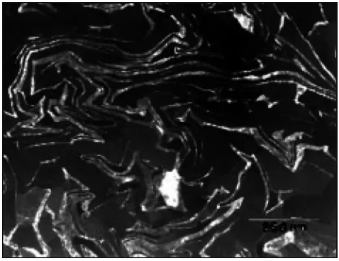
During the past two decades, a new class of copper-refractory metal composites has been developed with extraordinary mechanical and electrical properties (1-3). These composites, composed of face-centered cubic Cu with 10 to 30% by volume element X (where X is a body-centered cubic metal immiscible in Cu, such as Nb, V, Ta, Cr, or Fe), are severely deformed by extrusion/swaging/wire drawing or by rolling to produce the nanometer-scale microstructure of X filaments in a Cu matrix shown in Figure 1. The Cu-20%Nb system is the most thoroughly studied of these composites. These materials are best known for their extraordinary tensile strengths, which can be as high as 2400 MPa after deformation to a true strain (T) ) of 12 (4). However, they possess other unusual properties as well, including:
strength-to-electrical-resistivity ratios much higher than those of any copper alloy
the smallest filamentary microstructures (phase size) of any material available in bulk quantities phase structures with very low dislocation densities, approaching whisker quality in many cases
The Cu-X deformation-processed metal metal £omposites (DMMC's) are characterized byremarkable ductility, which allows cast- or powder-processed
88
[image:3.595.309.548.453.637.2]starting billets to be deformed as much asT)= 13.4 (5). Such deformations represent more than an 800-fold reduction in diameter and are accompanied by a concomitant reduction in the thickness and spacing of the X phase. Thus, an as-cast billet of Cu-20Nb, displaying Nb dendrites with an average thickness of
Figure 1 TEMmicrograph ofa Cu-20Nb DMMC at a true strain of9sectioned transversely and photographed in conical scan dynamic dark f1eld conditions to show the Nb f1laments as the light grey phase and the Cu matrix as the dark grey phase. Note that the Nb f1laments are typically 10 to25nm thick; their original thickness in the cast starting ingot
fll
=0) was5to 121J.m.Figure2Combined SEMphotographs oftransverse and longitudinal section views ofa Cu-20%Nb DMMC
frJ =3.6)arranged to depict its microstructuralphase shape in relation to the wire specimens overall dimensions. Note the convoluted ribbon shape ofthe bee Nb f1laments caused by the plane strain ofthe bee [110j tiber axis deformation texture. Fcc f1laments would remain approximately cylindrical in shape.
5/-1m, may be deformation processed at room temperature into a wire with Nb filaments averaging 7 nm thick (6). These insituprocessed composites have strengths substantially greater than the strengths of any
other Cu alloys. Debate continues on the
mechanismls) that account for the high strengths of the Cu-X composites (7-11), but discussion centers around the role of the nanofilamentary X structure in impeding propagation and motion of dislocations in both the Cu and X phases.
In an effort to extend these desirable deformation processing attributes to non-copper systems, the
authors have produced several DMMC's with
hexagonal close-packed
(Tt,
Y, Sc, and Mg), body-centered cubic (Nb, Fe, V, Mo,[3-
Ti). and face-centered cubic (AI, Au, and Ni) metals. This work began in 1990, and continues today (12-14). Twomajor conclusions can be drawn from these
experiments:
1. A large number of ductile metals can produce nano-scale DMMC's, and
2. Hexagonal close-packed (hcp) and body-centered cubic (bee) metals develop textures during axisymmetric deformation processing that cause plane strain in the developing filaments, forming convoluted ribbon-shaped filaments (see Figures
(€ii;}' Cold Bulletin1998,31 (3)
1-2). In contrast, face-centered cubic (fcc) metals with their larger number of slip systems do not deform in plane strain and are capable of forming filaments that are more nearly cylindrical in shape.
GOLD MATRIX DEFORMATION
PROCESSED METAL-METAL
COMPOSITES (DMMC'S)
The fcc structure of gold and the numerous
applications for gold requiring hardness, high strength, and high electrical conductivity suggest that gold would be an excellent candidate matrix for
a DMMC. However, equilibrium gold binary
systems with other ductile metals are not ideally suited for DMMC formation, since few gold binary systems possess the desired criteria of low mutual solid solubility and the absence of intermetallic compounds. Two systems that do meet these criteria
are Au-Rh and Au-Mo, and the authors first
attempted to make a gold DMMC with
melt-processed Au-Rh and Au-Mo specimens. However, in both systems the flow stress of the second phase metal is much higher than that of the gold matrix, and the second phase metals failed to plastically deform.
In binary systems where equilibrium phase diagrams are poorly suited to melt processing, an alternate method to prepare a DMMC is powder processing of the two metal powders. In such powder processed DMMC's, a microstructure consisting of the two elemental phases can be preserved by performing all processing steps at temperatures low enough to prevent formation of equilibrium microstructures.
P/M
may prove to be the only feasible means of producing Au matrix DMMC's, and this method was used to produce the Au-Ag DMMC described in the remainder of this paper.Experimental Procedure
Au powder of 99.95% metals basis purity and 1.6 to 6.8 urn particle size was mixed with Ag powder (99.9% metals basis purity) of 4 to 7 u.m particle
size. These powders were blended and cold
isostatically pressed at 138 MPa to form a 29.4-gram green compact of 90vol%Au and 10vol%Ag. The 11.1 mm diameter CIP' ed compact was sealed into a Cu can prior to deformation processing. The true strain of the specimen was calculated using the following equation:
do where, T) = true strain, do =original T)=21n
-d[ diameter, and d[=final diameter
This assembly was swaged at 295 K to a true strain of T)=3.7 (with appropriate adjustment for collapse of the 30% porosity of the CIP' ed compact), at which point the Cu was removed by etching in nitric acid, leaving a 1.45mm diameter Au-lOAg composite wire. The bare specimen was then wire drawn to a final diameter of 0.57mm (T)=5.6). Metallography specimens were prepared from the material at T)=3.7 and at T)= 5.6. Metallographic specimens were examined in an Amray 1845FE field emission SEM.
Gauge lengths for the five tensile specimens of the T)=5.6 material were reduced 10% in diameter by micro-grinding on a lathe. Tensile specimens were held in miniature pin vice grips and pulled at 295
K
at a strain rate of 0.0042mm/s. Ductility was determined by measuring the fracture surface diameter of each tensile specimen in a traveling optical microscope and comparing that value with the initial diameter of the tensile specimen.Electrical resistivity measurements were performed using the four-point resistance method at 295
K
on T)=5.6 Au-lOAg DMMC in the as-drawn condition and after annealing in air at 673K
for 600s, 2000s, and 10 OOOs.Results and Discussion
The deformation processing produced a microstructure of Ag filaments, roughly cylindrical in shape, in an Au matrix, as shown in Figures 3 and 4. The classic 'convoluted ribbon shape' of the Nb second phase filaments seen in Figures 1 and 2 is not seen in this Au-Ag DMMC. The fcc structure of the Au-Ag second phase has multiple slip systems, and the plane straining mode seen in bee Nb is absent in fcc Ag. For this reason, the Ag filaments change during deformation processing from equi-axed powder particles to filaments that are approximately cylindrical in shape. This behavior has been observed previously in fcc-fcc DMMC's, such as
the eutectic
Ag-Cu
DMMC of Frommeyer andWassermann (15) and the Cu-24 wt.% Ag DMMC of Sakai and Schneider-Muntau (16).
The ultimate tensile strength of the Au-lOAg T)=5.6 wire was 550 MPa (standard deviation = 34 MPa), and the ductility measured as reduction in area of the fracture surface was 16% (standard deviation 8.2%). The Vickers microhardness of the Au-lOAg wire was 95.3 VHN (standard deviation = 2.2 VHN) at T) = 3.7 and 131.2 VHN (standard deviation = 7.2 VHN) at T) = 5.6. In most DMMC's, the strength and
90
Figure 3SEM micrograph ofa longitudinal section of the Au-Ag composite wire (YJ =3.7). The darker bands are silver filaments in the (lighter) gold matrix in this back-scattered electron image. The indentation in the surface results from a Vickers microhardness test.
Figure 4 Micrograph ofa transverse section of the Au-Ag composite wire (YJ=56). The darker regions are silver filaments in the (lighter) gold matrix in this back-scattered electron image.
hardness increase as the mean true spacing between filaments decreases. Using the stereology methods of Underwood (17), mean center-to-center spacing
between the Ag filaments was measured from
transverse section micrographs using the relation:
1 CJ=
-N
Lwhere NL = number of particles intercepted per unit
length of circular test line and CJ = mean center-to-center spacing. Mean free path
(A.)
between the [image:5.595.308.546.96.282.2]Figure 5 Electrical resistivity versusannealing time in air at
673 K for Y]=56Au-lOAg DMMC. The lower horizontal line indicates the electrical resistivity ofthe as-drawn wire with no annealing. The upper horizontal line indicates the electrical resistivity ofa Au-Ag solid solution of this composition (18).
8.8% higher than the resistivity of pure gold (2.35 mOhm-cm) (19). Since the composite consists of pure silver filaments in a pure gold matrix with the filaments oriented parallel to the wire axis, the second phase presents a relatively small scattering cross section to current. By comparison, an annealed gold-silver solid solution of this composition was found by other investigators (18) to have a resistivity of 5.13 mOhm-ern and strength of 150 MPa.
The microstructure of the Au-lOAg DMMC is metastable. Given sufficient time at elevated temperature, the DMMC will diffuse to form the equilibrium solid solution microstructure. In an effort to characterize this process, pieces of the T)=5.6 Au-lOAg DMMC were annealed in air at 673 K for various time intervals, and the electrical resistivity of these specimens was compared to the resistivities of unannealed T)=5.6 Au-lOAg DMMC and a solid
o
100
filaments (sometimes called the mean edge-to-edge spacing) is given by the relation:
A= I-Pp
N
Lwhere
P
p is the volume fraction of Ag filaments. The average filament thickness (t) of the Ag fibres was measured from transverse section micrographs using the following equation:(l-pJ
t=----:,-:--N
Lwhere
PM
is the volume fraction of the matrix. In this Au-lOAg DMMC, the values for phase size and spacing are shown in Table 1.The 590 nm Ag filament thickness in the T)=5.6 Au-lOAg DMMC is much larger than the 10 to 20 nm filament thicknesses typically seen in DMMC's that have been deformed to higher true strains (1-4, 15), suggesting that the strength and hardness of this T)=5.6
Au-lOAg DMMC are probably well below the
maximum values attainable in an Au-Ag DMMC. Of the DMMC's previously studied, the system most similar to the Au-lOAg DMMC is the eutectic Ag-Cu DMMC of Frommeyer and Wassermann, which had ultimate tensile strength of 1450 MPa at T)=9.2. The considerable ductility of the T)=5.6 Au-lOAg DMMC also suggests that further deformation processing would be possible. The ultimate tensile strength of the Au-Ag DMMC is about four times greater than the
strength of pure annealed gold (18). The
microstructures of the Au-Ag DMMC of this study
and the Ag-Cu DMMC of Frommeyer and
Wassermann (15) are essentially identical in shape;
however, the Ag-Cu DMMC was deformation
processed to a higher true strain (T) = 9.2) and has much smaller filament thickness and spacing.
The electrical resistivity of the T)=5.6 Au-lOAg
DMMC was 2.556 mOhm-cm at 295 K, which is
6 U 5
§
6
4e
.>: 3 ..§. ~~
2'"
n::...
..
1000 104 Ann ealin g T ime (sec)
105
Mean center-ta-center Mean free path between Average fila m e n t spacing between Ag particles (A) in u.m th ickness (t) in u rn
filaments (<J') in u rn
NA* NA' 4 to1"
8.1 7.3 0 .81
6.0 5.3 0.59
a
3.7
5.6
Table 1Phase size and spacing for Au-lOAg DMMC deformed to Y] =3.7and Y] =5 6
True Strain (1))
* NA, not applicable; the specimen was not fully dense in theas-Clf'dcondition.
**Supplier's indicated Ag particle size. Some agglomeration of Ag particles may have occurred in powder processing of the Ag used in this study.
solution of this same composition, as shown in Figure 5. Even a 10 minute anneal at 673 K increases resistivity by more than 50%, presumably due to inter-diffusion of the two metals. This behavior is consistent with Fick's Law diffusion calculations; the diffusion coefficients for interdiffusion of Au and Ag are relatively high. Producing a gold DMMC with superior high temperature stability would require use of a second phase metal with a diffusion coefficient in Au smaller than in Ag. Several ductile metals suitable for deformation processing have diffusion coefficients in Au that are one to two orders of magnitude smaller than in Ag.
Potential for Further Development
The significance of this initial attempt at gold matrix
DMMC production lies not so much with the
properties of the T)=5.6 Au-lOAg DMMC per seas in the potential it heralds for substantially greater property improvements by refinements in the processing. Although the ultimate tensile strength of 550 MPa at T)=5.6 for the Au-lOAg DMMC is much higher than the strength of pure annealed gold, it is lower than the ultimate tensile strength of several precipitation-hardened gold alloys(egAu-1 wt%Ti with (JUTS = 1000 MPa) (20). It remains for future studies to determine whether deformation beyond T)=5.6 would further strengthen an Au-lOAg DMMC and whether the 10% Ag volume is optimal. The authors are preparing to deformation process several larger Au-Ag specimens to higher T) values and to measure their ductility, weldability, and electrical resistivity to explore these potential approaches to achieve higher strength. Additional studies of Au matrix DMMC's with a second phase metal other than Ag are also underway, and the authors hope to present these results in a second Gold Bulletin article when these studies are completed.
ACKNOWLEDGEMENTS
This research was supported by NASA's Iowa Space Grant Consortium and by Kulicke & Soffa Industries, Inc., Willow Grove, PA. The authors acknowledge their valuable discussions with T Ellis of Kulicke & Soffa
92
Industries and the work of L Jones, L Lincoln, P Wheelock, and E Zoellner of the Ames Laboratory Materials Preparation Center for preparing and analyzing the materials used in this study. This work was performed at Ames Laboratory, operated for the US Department of Energy by Iowa State University under contract no. W-7405-ENG-82.
REFERENCES
J Bevk, JP Harbison and JL Ben,JAppl. Phys.,1978,49 (12), 6031 6038
JD Verhoeven, FA Schmidt, E.D. Gibson and WA Spitzig,JMetals,1986, 38 (9), 20 24.
3 JD. Verhoeven, A Spitzig, LL Jones, HL Downing, CL Trybus, E.D. Gibson,
LS.Chumbley,LG. Fritzmeier and G.D. Schnittgrund,JMat Eng,1990, 12 (2), 127 ·139
WA Spitzig. and PD. Krotz,Acta Metallurgica,1988,36 (7), 1709 ·1715 JD. Verhoeven, WA Spitzig, FA Schmidt and CL Trybus,Mat Manu! Processes, 1989,4 (2), 197·209
JD. Verhoeven, WA Spitzig, FA Schmidt, PD. Krotz and E.D. Gibson,JMatSci. 1989,24,10151020
7 PD. Funkenbusch and TH Courtney,Acta Metallurgica,1985, 33(5).913·922
8 LS.ChumbleyH. Downing, WA Spitzig and JD. Verhoeven,MatSci.Eng, 1989, A117,59 65.
9 CL Trybus, LS.Chumbley,WA Spitzig and JD. Verhoeven,Ultramicroscopy, 1989, 30,315·320
10 PD. Funkenbusch and TH Courtney,Scripta Metallurgica,1989, 23, 1719·1724
11 WA Spitzig, JD. Verhoeven, CL Trybus and LS.Chumbley,Scripta Metallurgica etMateriaha,1990, 24, 1171·1174
12 JA Jensen, AM. Russen, TW Eilis and LS. Chumbiey, in i\iuminum and Magnesium for Automotive Applications'. ed. JD. Bryant and DR White, TMS Pubiications, 420 Commonweaith Dr., Warrendaie, PA, 1995
13 JD. Verhoeven, TW Eiiis, AM. Russen and LL Jones,
us
Patent 5,200,004,1993 14 AM. Russen, LS. Chumbiey, TW Eilis, FC Laabs,B.Norris and G.E. Donizetti,JMat Sci,1995, 30, 4249·4262
15 G.Frommeyer and G. Wassermann,Acta Metallurgica,1975, 23, 1353·1360 16 YSakai and H,J Schneider·Muntau,Acta Materialia,1997,45,1017·1023. 17 E.E. Underwood, 'Quantitative Stereoiogy', Addison·Wesiey, Reading, MA, USA
1970, pp. 80·93
18 E.M. Wise, 'Goid: Recovery, Properties, and Applications'. D. Van Nostrand Co., Princeton, NJ USA (1964) 88·104
19 HE Boyer and TL Gan, i\SM Metais Handbook', American Society for Materiais,
Materiais Park, OH, USA, 1985, 145
20 G.Humpston and DM.Jacobson,ColdBull1992, 25, 132·145
![Figure 5 Electrical resistivity versusannealing time in air at673 K for Y]=56 Au-lOAgDMMC](https://thumb-us.123doks.com/thumbv2/123dok_us/8130601.242112/6.595.307.545.331.491/figure-electrical-resistivity-versusannealing-time-air-au-loagdmmc.webp)
