Please cite this article as: M. Ganji, M. Bigdeli, D. Azizian, Mitigation Transformer Inrush Current Using Modified Transient Current Limiter, International Journal of Engineering (IJE), IJE TRANSACTIONS B: Applications Vol. 32, No. 5, (May 2019) 701-709
International Journal of Engineering
J o u r n a l H o m e p a g e : w w w . i j e . i rMitigation Transformer Inrush Current Using Modified Transient Current Limiter
M. Ganjia, M. Bigdeli*a, D. Azizianb
a Department of Electrical Engineering, Zanjan Branch, Islamic Azad University, Zanjan, Iran b Department of Electrical Engineering, Abhar Branch, Islamic Azad University, Abhar, Iran
P A P E R I N F O
Paper history: Received 04 August 2018
Received in revised form 09 January 2019 Accepted 07 March 2019
Keywords: Transformer Inrush Current
Modified Transient Current Limiter Simulation
Experimental Results
A B S T R A C T
This study presents a modified transient current limiter (MTCL) for mitigation the inrush current of transformers. The MTCL is based on conventional transient current limiter (TCL), which, its configuration is modified to overcome the TCL drawbacks of operation. The proposed MTCL offers lower power losses and voltage/current THD during normal operation mode. It needs only one limiting reactor instead of two limiting reactors, which results in cost saving. The theoretical analysis of the MTCL for suppressing the inrush current has been presented and the performance was tested by PSCAD/EMTDC simulation anda experimental prototype. Both simulation and experimental results showed that the MTCL is effective for suppressing the transformer inrush current. Also, the capability of the MTCL for suppressing the transformer inrush current was compared with the conventional TCL.
doi: 10.5829/ije.2019.32.05b.12
1. INTRODUCTION1
Transformers are key equipments of power systems. Their availability and the life time have major impact on grid reliability and efficiency [1, 2].
The energization of power transformers can cause saturation of the transformer magnetic core and flux asymmetries. This saturation leads to large inrush currents flow with a high DC component and a wide harmonic spectrum. Depending on the instant of energization and grid voltage, the amplitude of the inrush currents may increase to several times (up to 10-15) of the transformer rated current.
These large transient inrush currents will impose high thermal and electromechanical stress on the transformer winding and malfunction of differential and over current relays during the energization time [3, 4]. It may decrease the longevity of the transformer, and the system reliability. Therefore, to avoid these problems, the inrush current should be suppressed during the energization time [2–4].
In the literature, three main approaches have been proposed for limiting the inrush current of power
*Corresponding Author Email: [email protected] (M. Bigdeli)
transformers, which can be categorized as three following approaches:
Approach 1: Changing the internal structure of the transformer includes the winding structure and core magnetic characteristic [5–7].
Approach 2: Controlling the instant of the energization using a control circuit to control the switching angle [8, 9] and sequential switching of the phases [10–12]. Approach 3: Using impedance in the primary side of transformers [13–22].
The virtual air gap method has been present for limiting the inrush current of transformers [4]. In this method a DC current source uses to inject DC current in the auxiliary winding inside the core to reduce the permeability of the core. It has been reported in literature [5, 6], the primary and secondary coils of the transformer has been designed with an asymmetric winding distribution ratio to suppress the inrush current. In both solutions the transformer design consideration is more complicated, due to change in the transformer internal structure. Also, the efficiency of these methods for limitiging the inrush current is not significant.
Another approach to limit the inrush current include controlling the switching angle and the sequence of energizing each phase of the transformer. Both solutios require an additional detection and control energizing angle precise system. Lack of precision can result in large inrush currents at energizing instant. Moreover, independent operation of the circuit breaker poles is necessary to succeed in this approach [7–12].
Several types of current limiters (CLs) have been proposed for limting the transformer inrush and fault currents [13–22]. The application of the superconducting fault current limiter (SFCL) was recognized as an effective solution for limiting the transformer inrush current. Howevere, the high cost of superconducting material and cooling system are main drawbacks of SFCLs [14, 15].
The DC reactor-type inrush current limiter (DR-ICL) has been used for suppressing the inrush current [16, 17]. It has simple structure and requires any detection and control system. By using DR-ICL, the rate of rise of the transformer inrush current is suppressed by DC reactor without any delay and control system. Although, the utilization of the DR-ICL effectively suppresses the transformer inrush current. However, unacceptable distortion (THD) of the transformer voltage and current, high inductance value of the DC reactor and power losses of its resistance are the main drawbacks of the DR-ICL. A three-phase diode bridge-type ICL based on DR-ICL has been proposed [18]. The size of DC reactor and the number of diodes used in this structure is reduced; however, it is suitable for application of the ungrounded Y connected primary winding of transformers. The diode bridge-type ICL with an additional leg has been proposed in literature [19]. It effectively suppresses the transformer inrush current; however, it has the same drawbacks of the ICL presented in literature [18]. A voltage compensation-type ICL (VC-ICL) based on DR-ICL has been proposed to enhance theinrush current mitigation performance [21]. In this structure a DC voltage source is used in series with the DC reactor to compensate the power losses of the DC reactor during normal operation mode and limiting the increasing of the inrush current during the energization time. The DC compensation voltage source, includes a rectifier and multi output transformer. High construction cost and complexity in controlling the transformer ratio are the main drawbacks of this topology. Tseng and Chen [20] have proposed the bidirectional impedance-type ICL (BI-ICL) to enhance the aforementioned drawbacks of the DR-ICL. Compared to the ICL resented in literature [21], the BI-ICL has two DC reactors to mitigate the positive and negative inrush current. Although, the BI-ICL exhibits better performance than the DR and VC-ICL; however, its cost and power losses are higher than both ICLs. A transient current limiter (TCL) has been proposed in literature [22]. It is based on the BI-ICL, in which the DC
compensation voltage source has been eliminated to reduce the cost and complexity of the BI-ICL. It has simple configuration compared to the BI-ICL. But, it has the same drawbacks of the DR-ICL includes high power losses, unacceptable THD of the current and voltage waveform during normal operation of TCL.
Considering this background, this paper presents a modified transient current limiter (MTCL) for suppressing the transformer inrush current. The proposed MTCL has following advantages:
• It offers lower power losses and voltage drop during normal operation mode.
• It offers lower voltage/current distortion during normal operation mode.
• It needs only one limiting reactor instead of two limiting reactors of conventional TCL, which results in cost saving.
• It has superior performance for suppressing the inrush current.
To show the efficiency of the MTCL, the performance of the MTCL is compared with the conventional TCL through both simulation and experimental measurements. The simulations have been performed in PSCAD/EMTDC software.
2. TRANSFORMER MODEL
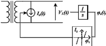
Representation of transformers is a fundamental necessity for the analysis of transient inrush current during energization period. The library of the PSCAD/EMTDC software provides a classical model for the transformer. In this model the transformer is represented by three separate single phase transformers with no coupling between phases [23]. In the classical models, the non-linear characteristics of the magnetic core are approximated based on the'air core reactance', the 'knee point' and the magnetizing current at the rated voltage and is represented by a compensating current source (Is). Figure 1 shows the modelling process of the transformer. The flux φs(t) is determined as a function ofthe integral of the low voltageside (VL) of the transformer. This characteristic can be derived from the open circuit test. Then, the magnetizing current is determined by the flux linkage through the nonlinear φs-Is characteristic, as shown in Figure 1.
The magnetizing current at rated voltageand the position of the knee point on the φs-Is characteristic determinesthe air core saturated reactance of the transformer. This asymptotic function is programmed internally within the PSCAD/EMTDC software. The details of this model have been represented in literature [23, 24].
3. MODIFIED TRANSIENT CURRENT LIMITER (MTCL)
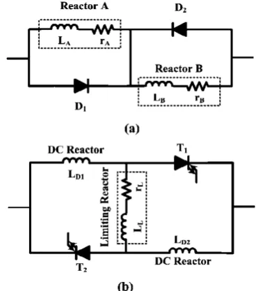
The power circuit and principle operation of the TCL has been described in literature [22]. It is inserted into each phase to mitigate inrush current as shown in Figure 2(a). Although, the utilization of the TCL in series with three phase transformer effectively mitigates the magnetizing inrush current; however, it has some drawbacks with its operation as follows:
It needs two limiting reactors to limit the positive and the negative cycle, increased current (reactor A for negative cycle and reactor B for positive cycle), which leads high cost of this structure.
Flowing the line current through the limiting reactors leads to high power losses of the MTCLdue to theresistance of the limiting reactor during normal operation mode of system. Operation of the TCL in normal and energization time result in unacceptable distortion in voltage and current waveforms.
3. 1. Configuration of MTCL To cope with the
aforementioned drawbacks of the TCL operation, the structure of the TCL has been modified in the first step.Also, In the next step, the control system is designed for proper operation of the MTCL.
The schematic diagram of the MTCL is illustrated in
Figure 2. Power circuit of (a) the TCL, and (b) the MTCL
Figure 2(b). It consists of the two small DC reactors (LD1 and LD2) to limit the rate of increasing transient current, two gate turn-off thyristor (GTO) semiconductor switches includes T1 and T2 and a limiting reactor (LR) to mitigate the transient current. The RL and LL introduce the resistance and inductance of the LR.
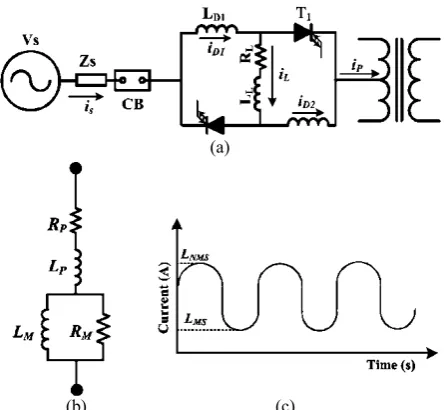
3. 2. Principle Operation of the MTCL The principle operation of the MTCL for limiting transient currents is based on changing the operation of the MTCL from normal operation mode to limit operation mode by switching the T1 and T2. The MTCL is able to limit transient currents such as short circuit current, motor starting current and transformer inrush current; however,the performance of the MTCL for transformer inrush current mitigation is presented in this work. Figure 3 shows the performance of the MTCL for limiting inrush current during energization inception. The normal operation mode of the MTCL includes before transformer energizing, short circuit fault and motor starting instants. During this mode, the T1 and T2 are turned on. Therefore, the line current flows for positive half cycle through T1 and LD1 and negative half cycle through T2 and LD2. The flowing current through the limtig impedaceis approximately equal to zero due to the large impedance of the limiting impedance, which offers low voltage drop and power losses during this mode.
The performance of the MTCL during energizing time of transformer is divided in two before and after switching of the T1 and T2. At first mode, the T1 and T2 are in on state and transient current flows through the LD1 and LD2. Therefore, the LD1 and LD2 suppresse the rate of increasing of the transient current at fault inception without any delay. It causes the DC reactor current (i.e. iD1 and iD2) increases with a constant rate. When the iD1 and iD2 raises to the threshold current (iT), the MTCL control system turn off the T1 and T2.
After, turn off the T1 and T2, the second mode is started. During this mode, the T1 and T2 are turned off by the control system and the limiting impedance is inserted in series with the line and the transient current is limited during this mode as shown in Figure 3.
Figure 3. MTCL operation during fault
(a)
(b) (c)
Figure 4. (a) Test system includes the MTCL and transformer, (b) Magnetising transformer model, (c) magnetizing inuctnace
3. 3. 1. Limiting the Rate of Rise of Inrush Current
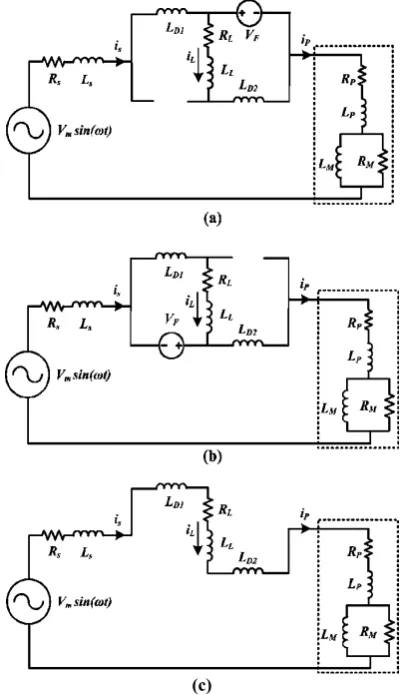
During this mode, the T1 and T2 are turned on. For positive half cycle operation, the T1 is forward biased and T2 is an inverse state as shown in Figure 5(a). Due to the large value of the RM ,it is assumed that the power loss of the iron core is neglected to simplify the analysis of the MTCL performace. During this state, the rate of rise of the inrush current is suppressed by the LD1. The current is can be derived by the following equation:
V sin ωt = L + V + Ri (1)
Where, L=Ls+LD1+LM+LP, R=Rs+RP and VF is the forward bias voltage of T1. By solving (1), the transformer current is expressed as follows:
i t =| |sin ωt − φ + | |sin ωt − φ −
e !" # (2)
where, |Z| = √R&+ Lω& and φ = tan ( )* .
Also, the limiting reactor current (iL) can be derived as :
V = L) "+ L+( " (3)
And,
i) t = 1 − e
!
" # (4)
For the negative half cycle operation of the MTCL, the T1 is inverse state and the T2 is forward bias as shown in Figure 5(b). During this state, the LD2 limits the rate of rise of inrush current.
3. 3. 2. Limiting Inrush Current When of the DC reactor currents (i.e. iD1 and iD2) reach to the there should value (iT) , the control system makes the T1 and T2 turn off. Figure 5(c) shows the equivalent circuit of the MTCL during this mode.
After turning off the T1 and T2, the limiting reactor is inserted in series with the transformer and limits the inrush current. In this state, the line current can be derived as follows:
V sin ωt = L + V + Ri (5)
Where, L=Ls+LD1+LM+LP, R=Rs+RP. Therefore, the line and transformer current (i) can be written as follows:
i t =| |sin ωt − φ + | |sin ωt(− φ e
!
" . (6)
where, |Z| = √R&+ Lω& and φ = tan ( )* .
After several cycles, the control system generates a high voltage level signal to turn on the T1 and T2. Therefore, the circuit operation returns back to normal operation mode.
3. 4. MTCL Power Losses The MTCL power
losses include loss of limiting reactor and GTO semiconductor switches T1 and T2. The power loss of T1 and T2 is derived as follows:
P012 = V( i (+ V& i & (7)
Also, the limiting reactor power loss is
P01) = R) i)& (8)
Therefore, total power losses of the MTCL are as follow:
(c)
Figure 5. Equivalent circuit for (a) positive half cycle (b) negative half cycle and (c) limiting inrush current mode
3. 5. MTCL Control System Control block diagram of the MTCL illustrated in Figure 6. In order to control of the MTCL for suppressing the inrush current of the transformer, the iD1 and iD2 is used as a control signal. At the first control loop, the ID1 is measured via a current transformer (CT) and compared with the permissible current level (i+∗) through the comparator (1). At the
second current loop, the ILD2 is measured via a CT and is compared with the i+∗ through the comparator (2).
Depending on the polarity of inrush current at the first cycle after energization, the DC reactor current increases as shown in Figure 3. If one of the iD1 and iD2 exceeds the i+∗, the control system makes the T1 and T2 turn off as
shown in Figure 6.
Figure 6. Control system of the MTCL
After 10 cycles delay, a rest signal is sent to the step generator to generate a high level signal and turns on the T1 and T2.
4. SIMULATION RESULTS
To investigate the efficiency and performance of the MTCL, the test system depicted in Figure 7, is used. Also, the performance of the MTCL is compared with the TCL. The test system, TCL and MTCL parameters data are given in Table 1.
The simulations were carried out for two transient conditions as follows:
4. 1. Transformerenergization In this condition
the transformer is investigated by closing the CB1 at t=1s and no-load condition (i.e. CB2 and CB3 are open). The transformer is energized for following scenarios: • Scenario A: Without using any current limiter • Scenario B: With using the conventional TCL • Scenario C: With using the MTCL
Figure 7. Simulated system
TABLE 1. Parameters of the simulated test system
Parameters Value
Grid
Source 10 kV
Frequency 50 Hz
Source resistanc 0.05 Ω Source reactance 1 mH
Transformer
Power rating 10 MVA
Voltage ratio 1
Rated frequency 50 Hz Leakage Reactance 0.1 pu Air core reactance 0. 1 pu Magnetizing current 2% In
MTCL
Ld 1 mH
LL 0.1 H
RL 1 Ω
VF 1.2 V
TCL LA=LB 0.1 H
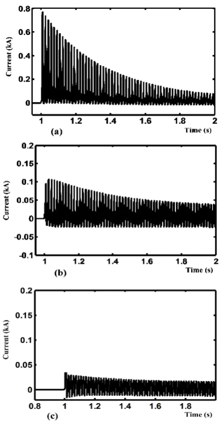
Figures 8(a), 8(b) and 8(c) show the transformer inrush current for scenarios A, B, and C, respectively. As illustrated in these figures, the inrush current of the transformer raises to the peak value of 0.8 kA at the energization instant for scenario A. By using the TCL and MTCL the peak value of inrush current effectively is reduced to 0.1kA and 0.05kA, respectively. Figure 9 shows the amplitude of the 2th-7th harmonic orders for all scenarios. As illustrated in this figure, the amplitude of the harmonic orders effectively is reduced by using the TCL and MTCL. However, the MTCL has minimum harmonic amplitude compared with the TCL.
4. 2. Fault Current Limitation As shown in
Figure 7, at this condition a three line to ground fault (3LG) is applied at t=4s. Figures 10(a), 10(b) and 10(c)
Figure 8. Transformer inrush current (a) Scenario A, (b) Scenario B, (c) Scenario C
Figure 9. Harmonic order for all scenarios
Figure 10. Short circuit current (a) Scenario A, (b) Scenario B, (c) Scenario C
current is increased to 2.3 kA at fault instant. In the scenario B, the rate of rise of fault current is limited by using the TCL, however, the fault current increases gradually and reaches to 1 kA after 10 cycles. By using the MTCL, the fault current is reduced to peak value 0.21 kA. Figure 11 shows the PCC voltage profile for all scenarios. As illustrated in this figure, the PCC voltage sag effectively reduced by using the MTCL compared with the TCL.
4. 3. Comparison of the TCL and MTCL In
comparison with other types of ICLs, the number of semiconductor switches used in the TCL and MTCL configuration is reduced from 12 to 6 for three-phase structure, which results in reduction of cost and increment of reliability. However, the semiconductor switches of the MTCL needs control system, which reduced the reliability compared with the TCL. Also, the MTCL has two DC reactors and one limiting reactor, however, the TCL has two limiting reactors. The inductance and current rating of DC reactors are very small compared with the limiting reactor, which results in reduction of power losses, current and voltage THD, voltage drop and increment of efficiency compared with the TCL. Comparison between the TCL and MTCL is shown in Table 2.
Figure 11. PCC voltage for all scenarios
TABLE 2. Comparison between the TCL and MTCL
Factors TCL MTCL
Power Losses (( VVD1 IL1+rA IL12)+
D1 IL1+rB IL12)
VF1 id1+ VF2 id2
+RL iL2
efficiency 99.7% 99.9%
THD 0.29% 0.12%
cost Moderate Moderate
(Less than the TCL)
Restriction No restriction No restriction
Auxiliary control system Not required required
5. EXPERIMENTAL RESULTS
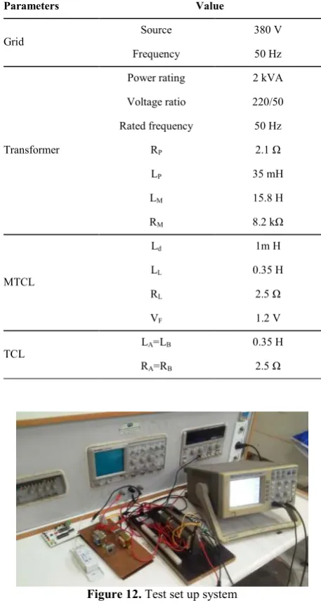
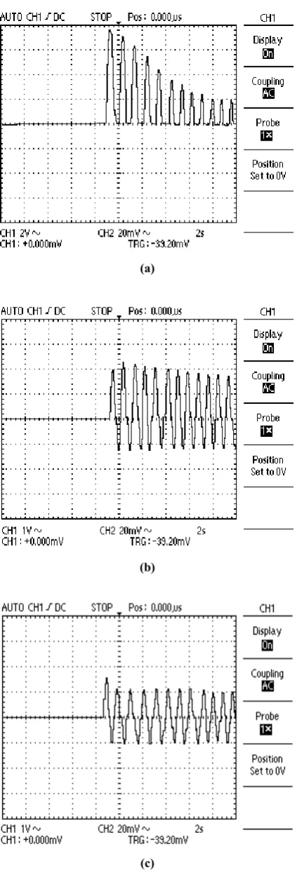
To show the feasibility of the MTCL a test setup has been built as shown in Figure 12. The parameters of test system are listed in Table 3. Figures 13(a), 13(b), and 13(c) show the transformer phase A current for scenario A, B, and C, respectively.
When the CB is closed at voltage phase angle 0, the transformer draws inrush current with peak value of 8 A as shown in Figure 13 (a). By using the TCL and MTCL the peak value of transformer inrush current reduced to 2.2 and 1.5 A at energization time. The experimental results shown in Figure 13 show the capability and the superiority of the MTCL over the conventional TCL. Figure 14 shows the DC reactor current, which is used as control signal.
TABLE 3. Parameters of the expermintal power circuit
Parameters Value
Grid Source 380 V
Frequency 50 Hz
Transformer
Power rating 2 kVA
Voltage ratio 220/50
Rated frequency 50 Hz
RP 2.1 Ω
LP 35 mH
LM 15.8 H
RM 8.2 kΩ
MTCL
Ld 1m H
LL 0.35 H
RL 2.5 Ω
VF 1.2 V
TCL LA=LB 0.35 H
RA=RB 2.5 Ω
(a)
(b)
(c)
Figure 13. Transformer inrush current (a) Scenario A, (b) Scenario B, (c) Scenario C
Figure 14. DC reactor current
6. CONCLUSION
This paper proposes a modified transient current current limiter (MTCL) for supporting the transient, include transformer inrush current and fault current. It needs only one limiting reactor instead of two limiting reactors of the conventional TCL, which results in the cost, weight and volume of the MTCL to be accordingly reduced. Also, it offers lower power losses and voltage drop during normal operation mode in comparison with the TCL. Furthermore, both simulation and experimental results reveal that the proposed MTCL has superior performance in comparison with the TCL.
7. REFERENCES
1. Moradi, A. and Madani, S. M., “Technique for inrush current modelling of power transformers based on core saturation analysis”, IET Generation, Transmission & Distribution, Vol. 12, No. 10, (2018), 2317–2324.
2. Ebadi, A., Hosseini, S. M., and Abdoos, A. A., “A New Restricted Earth Fault Relay Based on Artificial Intelligence”,
International Journal of Engineering - Transactions A: Basics,
Vol. 32, No. 1, (2019), 62–70.
3. Bhatt, G., Tadlock, T., and Ristanovic, D., “Transformer Energization From Low-Voltage Side With Limited Generation—Power System Constraints and Protection Considerations—A Case Study”, IEEE Transactions on
Industry Applications, Vol. 54, No. 2, (2018), 1861–1869.
4. Hamilton, R., “Analysis of Transformer Inrush Current and Comparison of Harmonic Restraint Methods in Transformer Protection”, IEEE Transactions on Industry Applications, Vol. 49, No. 4, (2013), 1890–1899.
5. Molcrette, V., Kotny, J.L., Swan, J.P., and Brudny, J.F., “Reduction of inrush current in single-phase transformer using virtual air gap technique”, IEEE Transactions on Magnetics, Vol. 34, No. 4, (1998), 1192–1194.
6. Chen, S.D., Lin, R.L., and Cheng, C.K., “Magnetizing Inrush Model of Transformers Based on Structure Parameters”, IEEE
Transactions on Power Delivery, Vol. 20, No. 3, (2005), 1947–
7. Chen, J.F., Liang, T.J., Cheng, C.K., Chen, S.D., Lin, R.L., and Yang, W.H., “Asymmetrical winding configuration to reduce inrush current with appropriate short-circuit current in transformer”, IEE Proceedings - Electric Power Applications, Vol. 152, No. 3, (2005), 605–611.
8. Brunke, J.H. and Frohlich, K.J., “Elimination of transformer inrush currents by controlled switching. I. Theoretical considerations”, IEEE Transactions on Power Delivery, Vol. 16, No. 2, (2001), 276–280.
9. Brunke, J.H. and Frohlich, K.J., “Elimination of transformer inrush currents by controlled switching. II. Application and performance considerations”, IEEE Transactions on Power
Delivery, Vol. 16, No. 2, (2001), 281–285.
10. Cui, Y., Abdulsalam, S. G., Chen, S., and Xu, W., “A Sequential Phase Energization Technique for Transformer Inrush Current Reduction— Part I: Simulation and Experimental Results”, IEEE
Transactions on Power Delivery, Vol. 20, No. 2, (2005), 943–
949.
11. Cano-González, R., Bachiller-Soler, A., Rosendo-Macías, J.A., and Álvarez-Cordero, G., “Controlled switching strategies for transformer inrush current reduction: A comparative study”,
Electric Power Systems Research, Vol. 145, (2017), 12–18.
12. Cano-González, R., Bachiller-Soler, A., Rosendo-Macías, J.A., and Álvarez-Cordero, G., “Optimal gang-operated switching for transformer inrush current reduction”, Electric Power Systems
Research, Vol. 131, (2016), 80–86.
13. Firouzi, M., Gharehpetian, G.B., and Pishvaie, M., “THD reduction of PCC voltage by using bridge-type fault current limiter”, International Transactions on Electrical Energy
Systems, Vol. 23, No. 5, (2013), 655–668.
14. Shimizu, H., Mutsuura, K., Yokomizu, Y., and Matsumura, T., “Inrush-Current-Limiting With High Tc Superconductor”, IEEE
Transactions on Appiled Superconductivity, Vol. 15, No. 2,
(2005), 2071–2073.
15. Seo, H.C., Kim, C.H., Rhee, S.B., Kim, J.C., and Hyun, O.B., “Superconducting Fault Current Limiter Application for
Reduction of the Transformer Inrush Current: A Decision Scheme of the Optimal Insertion Resistance”, IEEE
Transactions on Applied Superconductivity, Vol. 20, No. 4,
(2010), 2255–2264.
16. Abapour, M., Taghizadegan, N. and Sharifian, M.B.B., “A novel approach for reducing inrush current in power transformer”, In Proceedings of International Conference on Electrical Machines, Chania, Crete Island, Greece, (2006), 2-5.
17. Tarafdar Hagh, M., and Abapour, M., “DC reactor type transformer inrush current limiter”, IET Electric Power
Applications, Vol. 1, No. 5, (2007), 808–814.
18. Madani, S. M., Rostami, M., and Gharehpetian, G. B., “Inrush current limiter based on three-phase diode bridge for Y-yg transformers”, IET Electric Power Applications, Vol. 6, No. 6, (2012), 345–352.
19. Madani, S. M., Rostami, M., and Gharehpetian, G. B., “Improved bridge type inrush current limiter for primary grounded transformers”, Electric Power Systems Research, Vol. 95, (2013), 1–8.
20. Tseng, H.T. and Chen, J.F., “Quasi-bridge-type fault current limiter for mitigating fault transient phenomena”, IET
Generation, Transmission & Distribution, Vol. 8, No. 8, (2014),
1377–1391.
21. Tseng, H.T. and Chen, J.F., “Voltage compensation-type inrush current limiter for reducing power transformer inrush current”,
IET Electric Power Applications, Vol. 6, No. 2, (2012), 101-110.
22. Amiri, P. and Akhbari, M., “Transient current limiter for suppressing transformer inrush, motor starting and fault currents in power system”, IET Electric Power Applications, Vol. 11, No. 3, (2017), 423–433.
23. Dommel, H.W., “Transformer models in the simulation of electromagnetic transients”. In Proceedings of 5th Power Systems Computation Conference, (1975), 1-5.
24. PSCAD/EMTDC V3.0.8, Power System Simulation Software User_Manual, Manitoba HVDC Research Center, Canada, 2001.
Mitigation Transformer Inrush Current Using Modified Transient Current Limiter
M. Ganjia, M. Bigdelia, D. Azizianb
a Department of Electrical Engineering, Zanjan Branch, Islamic Azad University, Zanjan, Iran b Department of Electrical Engineering, Abhar Branch, Islamic Azad University, Abhar, Iran
P A P E R I N F O
Paper history: Received 04 August 2018
Received in revised form 09 January 2019 Accepted 07 March 2019
Keywords: Transformer Inrush Current
Modified Transient Current Limiter Simulation
Experimental Results
! "#$ %$ & "'( )
" "* + .-
."/0 1 ) 23/4 5
! ) 23/4 6 0 "78) "'( ) 9 &
9 :
.-; 74 ; *3
/& " < 7 /& = > "4 )
-! "/0 " & ? @ A 8(BC1 C(D/$ . ((&
& ) "
((& * ( :$ %$ & E4 ) & - )
& 9 C ! "#$ %$ & ) !
"F ) .
9 ! & GH + I @ " ! "#$ %$ & )
7C 9 JB !$
I .- A K ! ) " 7C 9 !$ JB B ! $ & "#$ !)" ) 8(BC1
!
" "* !
(& ) -7 8) 23/4 ! "/0
-.