1
Voltage Coordination of FACTS Devices in Power Systems
Using RL-Based Multi-Agent Systems
M. R. Tousii ٭, S. H. Hosseinianii and Mohammad B. Menhajiii
i* Corresponding Author, M. R. Tousi is PhD student in Department of Electrical Engineering, Amirkabir University of Technology, Tehran, Iran (e-mail: [email protected]).
ii S. H. Hosseininan is with the Department of Electrical Engineering, Amirkabir University of Technology, Tehran, Iran (e-mail: [email protected]).
iii M. B. Menhaj is with the Department of Electrical Engineering, Amirkabir University of Technology, Tehran, Iran (e-mail: [email protected]).
ABSTRACT
This paper describes how multi-agent system technology can be used as the underpinning platform for voltage control in power systems. In this study, some FACTS (flexible AC transmission systems) devices are properly designed to coordinate their decisions and actions in order to provide a coordinated secondary voltage control mechanism based on multi-agent theory. Each device here is modeled as an agent being able to cooperate and communicate with other devices. In this system, individual autonomous agents and intelligent decision makers learn to perform optimal actions through proper interactions with their environments. The SARSA Q-learning, which is an on-policy algorithm in reinforcement learning (RL) is then used and tested successfully in voltage control problem. In this research, the Java Agent DEvelopment (JADE) platform is used to implement the agents and to simulate their communications. The power system is also fully implemented in Java. The proposed intelligent MA based method is finally applied to IEEE 39-buses New England power system. The results of simulation better highlight the merit of the method and its ability in coordinating FACTS devices for removing voltage disturbances.
KEYWORDS
Multi-Agent Systems (MAS), Secondary Voltage Control, Voltage Coordination, Reinforcement Learning, Java Agent Development (JADE) Framework.
1. INTRODUCTION
The control of voltage is one of the major issues in power system operations and reactive power plays a significant role in controlling the voltage in power systems. Adding static reactive power compensator devices such as FACTS at some nodes of the power systems is one of the solutions used to achieve and maintain the required voltage profile.
The voltage control in power systems has three main levels with different response times. The first level is primary voltage control which comprises the automatic voltage regulator (AVR) of generators, fast reactive insertion and FACTS devices. The response time of primary voltage control is short, typically fractions of a second [1]. In the secondary voltage control level, the objectives are to attain a better voltage regulation and improvement of power system voltage stability in various system conditions, such as slow and large voltage variations caused by hourly evolution of the loads [2]-[3]. The reaction time in this control level is about one minute or more (usually 30-100sec). Tertiary voltage control uses global information of the power system for managing
reactive resources to optimize voltage profile. The traditional method of tertiary control is so-called reactive power optimal power flow (OPF). The time constant of this control level is around 15 minutes.
nodes in regions are selected for voltage regulation. These nodes are representative of the voltage situation in that region [6]. The main actuators are the set-point voltages of the primary controllers of the generators within a region, capacitors, reactors, synchronous machines, transformer taps and FACTS devices. Gaining advantages of FACTS devices in electric power system requires coordination of these controllers with each other. Otherwise, endangerment of dynamic behavior and steady-state of power system is to be expected. In [2], [3] and [7], the coordination of various controllers has been proposed to be based on a multi-agent request-and-response type of protocol.
In this research, multi-agent systems technology provides a framework for developing autonomous and intelligent agents for coordination of voltage control mechanism in power system. In this system, individual agents who must be autonomous and intelligent decision makers learn to perform optimal actions by interaction with environment. The SARSA algorithm which is an on-policy algorithm in reinforcement learning (RL) has been used for this application. For developing agents and implementing communication in an adaptive coordination system, a MAS platform is needed. JADE [8] platform was chosen because of its good capabilities and logical structure for this research.
This paper is structured as follows. Section 2, presents a brief overview about agent technology in power system. In section 3, a review on JADE framework is provided. The proposed Multi-Agent based coordinated secondary voltage control scheme is presented in section 4. Section 5, describes the Reinforcement Learning approach and results obtained by the application of SARSA Q-learning algorithm for voltage control in power system. Simulation and analyzing results of some test cases are presented in section 6. In section 7, some test cases on performance of proposed method are presented. The final section provides some conclusions.
2. ABRIEF REVIEW OF MULTI-AGENT SYSTEMS IN POWER SYSTEMS
An agent is anything that can perceive its environment through sensors and act upon that environment through actuators [15]. It can communicate with other agents in an environment to achieve its local or global objectives. MAS is a system that is composed of agents, collectively capable of reaching goals that are difficult to achieve by an individual agent or monolithic systems [16]. MAS is one of the most popular approaches for designing decentralized solutions.
The use of agent is to remove the burdens of human beings from tedious and repeating tasks. In power systems functions of each agent can be categorized into two main groups. The first one is agent’s processing or application functions such as data processing, simulation and control function. The second group is the agent’s behavioral
characteristics. An agent regarding its own capabilities and functions must have decision making intelligence. By providing agents with underlying standards for agent communications, they will be able to dynamically organize themselves into problem solving. Agent technology brings many opportunities and benefits for power systems which can be summarized as follows:
• Ease of interfacing with other software
(encapsulating them into agents for interoperability within a larger infrastructure)
• Simplifying complex systems modelling
• Decomposing large complex problems into
sub-problems
• Ease of modelling humans and knowledge in
simulation environment
• Modularity and reusability
• Distributed nature
• Increasing flexibility, scalability, reliability and system robustness since it does not suffer from the "single point of failure" problem
• Increasing speed and efficiency of system
• Ease of adding or replacing new agents
(especially during a simulation without interruption.)
• Providing social abilities for agents by
communication
• Automated adaptation to changing environments
• Reduction of the human interactions with system
• Behavior coordination through cooperation,
negotiation or mediation
• Reduction of network consumption due to the
agent oriented approaches.
In multi agent based simulation, there is a close match between the entities of the reality, the entities of the model, and the entities of the simulation software. This simplifies both the design and the implementation of the software [11]. In this model of power systems, there are various agents based on the tasks that they can perform, their complexity, the level of intelligence, the level of communications and control allowed by each agent, and the amount of information they can acquire from the system.
The agents in MAS can interact with one another. There are various approaches for implementing MAS in system control concepts: centralized, decentralized, hierarchical, etc. In this study, decentralized method was selected because of many advantages of the decentralized approach respecting other methods [17].
their behaviors to the environment. Additionally, current MAS applications on power systems are topology dependent. This study tries to find a way to be free from this dependency by using autonomous agents. Except in [17] and [18] almost in all of the simulations and applications of MAS in power systems, the MAS and the power system are implemented on the same PC and also using single threaded programming environments. So they cannot execute two or more programs in parallel and also peer-to-peer message transfer is not possible. Therefore, we need a multi-thread platform that allows us to research real performance and communication bandwidth requirements of the MAS.
In recent years, standards for agent organization and communications have been developed. One organization that defines and publishes standards is the Foundation for Intelligent Physical Agents (FIPA) [9]. Several FIPA compliant frameworks have been proposed. Among them the JADE was chosen because of its good capabilities and logical structure. JADE at this time is the most commonly used FIPA compliant platform. In the next section a brief review on JADE is provided.
3. JADEOVERVIEW
JADE is a Java-based middleware for the development of distributed multi-agent applications based on the peer-to-peer communication architecture [8]. Middleware is a software platform that provides another layer of separation between the software and the underlying operating system [8]. In this implementation, the underlying operating system is the Java Virtual Machine, the middleware is JADE and the application is the code for the agents written in Java. JADE at this time is the most commonly used FIPA platform. It is also an open source project distributed by TILab (Telecom Italia Labs). JADE is a very flexible platform and can be adapted to be used on devices with limited resources (such as PDAs and mobile phones).
JADE’s architecture is based on a modular structure, in which a platform is split into a number of containers, which may run on different machines. An instance of the JADE is created when the execution begins, and it is called a container because it contains agents. A single special “Main container” must always be active in a platform and all other containers register with it as soon as they start. Three agents are automatically activated with the JADE start-up, which includes AMS, DF and ACC. All agents, including these, communicate via the Internal Platform Message Transport (IPMT). Agent Management System (AMS) provides white page and life cycle service, maintaining a directory of agent identifiers (AID) and agent state. AMS supports the modification of the agents during run-time.
Directory Facilitator Agent (DF) is used to provide yellow page services and the capability to search agents with specific capability. It maps service descriptions to
Agent Identifiers. In a system consisting of only a few agents, it is possible to provide the knowledge about other agents in the system manually, or to use a broadcast-based protocol, such as the Contract Net Protocol [3], in order to locate other servicing agents. However, as the number of agents increases, it becomes so difficult for agents to locate others which provide services that they require. This problem can be addressed by the use of Directory Facilitators [19]. By using DF, agents do not have to be aware of the other agents. Agent Communication Channel (ACC) is the software component controlling all the exchange of messages within the platform, including messages to/from remote platforms. In JADE, the agent functions are implemented in behaviors. The behavior is a function that is running recursively in the agent to implement the function of the agent. Each agent can have so many behaviors in its behavior pool. The JADE behavior model allows an agent to execute several parallel tasks. All active behaviours get executed with equal frequency. There are so many predefined behavior subclasses in JADE which can be executed or customized in order to create the required agent capabilities. Adding behavior should be seen as a way to spawn a new execution thread within the agent. Fig.1, shows different stages of agent execution in JADE. In setup, initialization of agent is carried out while execution of behaviors occurs in action. After the action, if the agent’s behavior is finished the behavior is removed from the behavior pool and other behaviors continue execution. Behaviors and sub-behaviors can be added whenever is needed, and not only within Agent.setup() method. Adding a behavior should be seen as a way to spawn a new execution thread within the agent.
Figure 1: Agent execution in JADE [8] No
Yes No
Yes
-Clean-up operations
-Agent “life” (execution of behaviours) -Initializations -Addition of initial behaviours Setup ()
Agent has been killed
(doDelete () method called)?
Get the next behaviour from the pool of active behaviours.
b.action ()
b.done () ?
Remove current behaviour from the pool of active behaviours.
4. MULTI-AGENT BASED COORDINATED SECONDARY VOLTAGE CONTROL
In this section, the multi-agent system framework and power system voltage coordination and collaboration protocol are introduced. In this framework, JADE is used as underlying agent infrastructure and can be combined with other tools and approaches to program the agents’ behavior. Fig.2 shows a graphical representation of this MAS. Each component in the power system is represented as an agent in the simulator. According to the electric component to which an agent is associated, the agents in MAS can be classified into some types. Each agent type has its specific rules for performing its functions. In this MAS, there is no central controller or coordinator. Each agent works autonomously and independently. Thus, the MAS works in a completely decentralized manner.
Figure 2: Graphical representation of MAS for power system.
Individual agents can be both clients and servers for different services in different times. All of the agents who need information in order to perform their functions can send a request query to the directory facilitator to find an agent (or agents) that can offer requested information. The facilitator finds the agent who can provide this information and replies the requesting agent. After that, requesting agent can subscribe itself to the founded agent for information.
For implementing agents, their objectives, behavioral rules and interaction mechanisms with environment as well as other agents must be defined. Some major agent types and their functionalities are described below:
- Servicing Agent
Servicing Agent (SA) is used to provide a special service like shunt or series reactive power compensation. These SA agents are able to perform some actions separately or in coordination with other agents. The servicing agents are categorized based on their service type. So, many service types can be defined based on
application requirements. These agents hold some rules and computing functions to negotiate with other agents. Some of the SA’s can be utilized by intelligent control systems and learning algorithms to provide more autonomy and elasticities for the system. They can provide the reference set points of controllers autonomously, considering operational constraints and their self interests with some priorities. In this paper, the SAs correspond to STATCOMs and provide only shunt reactive power for the power system in a specified bus.
- Load Flow Agent
Load Flow Agent (LFA) that performs load flow calculations. The LFA plays the role of power system environment. All of the components in the power network are modeled in this agent. Other agents that need to know their state values (such as voltage or current) and other system measurements invoke their status from this agent by continually sending requests to it. The load flow agents can register themselves in DF. So, when each component agent wants to initialize in MAS, searches for available LFA to query for its status. Whenever the LFA receives a control action message from agents, it immediately implements the action in the power system model. Agents can subscribe to LFA to achieve their values every time that they change. It can also be implemented by using a TickerBehavior (a type of JADE’s behaviors which implements a cyclic task that must be executed periodically) to send a request of voltage value to LFA in each predefined time steps.
- DC Load Flow Agent
DC Load Flow Agent (DCLF) can be created by instantiation of LFA agent to perform DC load flow and sensitivity analysis. This agent is used as an analyzing agent who can perform some calculations and analysis on the power system. This agent registers itself in DF as a DCLF service provider.
- Bus Agent
Bus Agents (BA) who can monitor their buses and have no service to provide. In this work, each bus agent in the system has a unique priority number based on the importance of the bus. The commands of bus agents with higher priorities are more important than the others, and servicing agents will serve them first.
- Sniffer Agent
One of the useful agents in JADE is Sniffer Agent that can intercept Agent Communication Language (ACL) messages while they are in flight, and displays them graphically. It is useful for debugging the agents’ activities and can help monitoring and checking the messages exchanged among agents.
The objective of the control in this MAS is to minimize deviations of bus voltages from given references to improve the voltage profile.
The process of coordination and collaboration among agents and their behaviors are described below.
Network Protocol Stack
JRE JRE JRE
Distributed Agent Platform
Main Container Container 1 Container 2
Load
F
low
Agent
S
e
rvic
ing
Agent
Host 1
De
vice
Agent
Da
ta
b
a
se
Ag
e
n
t
Host 2 Host 3
Bu
s
Age
n
t
Se
rvic
ing
Agent
AM
S
A
g
en
t
Sn
if
fe
r
A
g
e
nt
DF
A
g
en
t
D
C
LF
Agen
t
Bu
s
A
gen
1) Each agent must register itself in DF based on its service type and the bus belongs to.
2) All agents find the LFA and DCLF agents in DF. 3) Each agent monitors the voltage of its own node. 4) Once a bus agent detects a voltage violation, it searches the DF for available SAs. Agents invoke their voltage sensitivity respecting reactive power injection in SA buses by sending request to DCLF agent and it will respond these requests. The SA agents which have low voltage sensitivity with respect to the requester bus agent will be ignored from collaboration process. The BA will
then send SAs, Call For Proposal (CFP) message to
know the maximum collaboration they can provide. By this method there is no need to define a static group of collaborative agents in the system and based on the system available resources and operating conditions decision can be made more exactly and rapidly.
5) Sometimes one SA cannot provide any service because of its internal problems or reaching its operational limits (such as maximum reactive power injection). In this case, the SA must deregister itself from
DF. When a SA agent receives a CFP message for
reactive power support, it checks its capacity and its own voltage. It computes its maximum collaboration based on its available capacity and voltage of other remote controlled buses under its supervision and also by estimation of future agent’s state by doing any action. This gives it an estimation of the amount of support it can offer and can avoid elapsing time for unnecessary and
imperfect decisions. Then, it sends back a Proposal
message to the source of request to tell its offer of
support;
6) The BA waits for a predefined time for receiving all of the SAs’ responses and offers. Based on these information and decision of decision making unit (DM) which was learned priori by RL algorithm, the bus agent
sends Request messages to the selected SAs to do the
proposed actions. In contrast with the method described in [3] where agents are selected one after one and also in a not optimal configuration, in this method the decision is based on RL and gives the optimal or near optimal solution; and further, since more agents contribute in collaboration at the same time the overall performance and speed of secondary voltage control will be increased.
7) After the SAs perform the proposed actions, they
send an Inform message to bus agent about termination of
their actions. If the voltage violation disappears, the agent returns to the normal state.
For SA agents operation there are some other considerations that must be illustrated individually:
a) When a SA runs to perform an action it must go to Block Action state for a short time. The reason is that if during operation of SA, some action request from another agent comes to this SA, since the agents are not aware of other agent’s action there is a possibility of over injection
in the network. For resolving this problem, during operation of some action, if another request is received, this message will be returned back to its origin to check its new state again. This blocking time can be defined based on problem conditions.
b) If SA detects voltage violations on its own bus, it will do its action locally and will block other requests until violations get eliminated. In fact, each SA is self interested.
c) If any of the above processes did not suffice to overcome the voltage violation, the function of multi agent CSVC system will be terminated and another process like load shedding must be called.
Sometimes there is a possibility of facing with action conflicts between agents. This may be created in some situations where the goal of an agent is in contrast with goal of another agent. For avoiding this situation, we must design two distinct mechanisms. First implementing a mechanism to avoid creation of conflict and the other is what to do for resolution of conflict when it occurred in a system. The conflicts can be resolved by negotiation, mediation or arbitration process.
Since the agent lacks the information about control
objectives and actions of other agents, it has to introduce an assumption about the actions of other agents to remain constant when trying to compute its optimal control policy. But this assumption is not correct generally. Therefore, these actions of other agents can be seen as measured disturbances [21].
Another solution is sharing the action information of each agent in the network. By this method, since the agents are aware about actions of others they do their decisions based on this knowledge. There are so many methods for conflict avoidance and resolution in multi-agent systems that are beyond the scope of this paper.
The most important and crucial step in the above process is the calculation of optimal or near optimal control sequence of SAs for taking the most effective control action in contingencies. This function is due to DM unit trained with RL algorithm that is fully discussed in the next section.
5. REINFORCEMENT LEARNING
itself to changing conditions.
The objective of coordination of FACTS devices is to maintain acceptable voltage profile on the network with the minimum usage of reactive resources. The algorithm determines the control commands that will activate the switching of the proper reactive resources (STATCOMs) and their amount of injection. The algorithm selected for this purpose is one of well known RL algorithms named SARSA.
SARSA is an on-policy temporal difference (TD) learning algorithm and is referred to as tabular learning, since it stores its representation of the world discretely in a lookup table. The general principle of SARSA is summarized by its name: State, Action, Reward, State, Action. In SARSA, an agent starts in a given state st, from
which it selects an action at based on selection policy and
does the selected action. After the action, the agent
receives an immediate reward rt, expressing the
effectiveness of the action and goes to a new state st+1
from which it can take another action. The goal of RL is to take these experience tuples (st, at, st+1, at+1), and learn a
mapping from states and actions, to a measure of the long term value of taking this action, known as the optimal value function (Q-value) [10]-[12].
The algorithm proceeds as follows:
TABLE 1
SARSA ALGORITHM APPLIED TO VOLTAGE CONTROL
1) All Q(s,a) values are initialized. 2) Repeat for each episode {
Initialize st(create a random initial state).
Choose atfrom stusing ε-greedy selection policy.
Repeat for each step in the episode{
Take action at, observe r and st+1 (Do load flow)
Choose at+1from st+1 using ε-greedy selection policy
[
( , ) ( , )]
) , ( ) ,
(st at Qst at rt1 Qst1at1 Qst at
Q = +α + +γ + + −
1
1, +
+ =
= t t t
t s a a
s
If is final state end the episode
(final state means that all voltages are inside the
boundaries) }
}
3) After each k episodes check the D value (checking the convergence)
In RL algorithms, there must be a tradeoff between exploration and exploitation. An exploratory action or
exploiting action is chosen based on a policy such as ε
greedy which operates on a simple principle of selecting the most optimal action based on the current rewards or Q-values for all possible state action pairs. In addition, there is some probability ε that the selection policy will choose an action randomly to explore the world in the hope that it may lead to a better solution.
The state variables in our problem are voltages of buses. The state vector corresponding to each agent
comprises its own voltage, servicing agents’ voltages and critical buses voltages in its region. By defining this state vector agent must be aware of its state as well as other important nodes in the system to make a proper and efficient decision. For applying the algorithm, each state variable must be divided into some levels as a discrete variable. The state discretization can be done in many different ways. One way is binary discretization which already implemented on constraint load flow problem [13]. Through finer discretization, the results of learning will change and usually get improved; however by reducing discretization intervals the dimension of state space will be increased exponentially. Hence,, it must be some tradeoff between the quality of learning and the size of discretization. Here, it is decided to discretize the states to 5 levels. These levels are: below the 0.85 p.u, between 0.85 p.u. and 0.95 p.u, between 0.95 and 1.05 p.u, between 1.05 p.u and 1.10 p.u. and at last above 1.10 p.u. Consequently, we can say that if we have n variables discretized to m levels, the total number of states will be:
(1)
n
m
S
=
In this application, the control variables are actions of STATCOM agents which can be considered as voltage set point or as reactive power injection. Since changing the voltage set point of STATCOM is equivalent to the value of bus injected reactive power, we work here with reactive power values for the ease of simulations. Furthermore, each control variable has to be discretized to ki levels. Hence, the total number of joint action vectors
will be:
(2)
pi i
k
A
1 =
=
where p expresses the number of control variables. In this study each control action is discretized into five levels.
(3).
where ns and nc are number of servicing agents and
critical buses, respectively. The ws, wc,wq are weighting
factors of corresponding components.
To check whether the algorithm converges to good solutions and in turn stop the learning after running some epochs, we should have a stopping criterion. When there
are no significant changes in Q-values and also no new
states visited, it means that system reached a stable condition and consequently np more learning is needed.
So, after each K epochs (in our simulation we set it to
2500 epochs), a vector of Q-values is constructed and
the unsigned differences of all Q-values corresponding to
state-action pairs in two subsequent K epochs will be
calculated as: (4)
∑
−
=
) ,(sa( , ) (, ) all for old a s new a s
Q
Q
D
If the value of D converges to zero or a given threshold, the learning will be stopped.
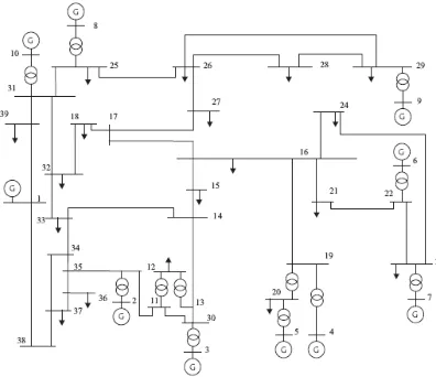
The algorithm was applied to IEEE 39-buses New England power system shown in Fig. 3. Four STATCOMs are assigned at nodes 13, 14, 33, 37 to enhance the voltage stability. The critical buses are selected as buses 12 and 16.
Since we discretized state variables to five levels and the size of state vector is seven (four SA, two critical
buses and the agent itself) we have 57=78125 state
vectors. The number of action vectors is 54=625.
Therefore, the total number of state-action pairs is 625×78125=48828125.
The next step is the issue of parameterization. Three parameters α , γ and ε should be chosen. The amount the next step influences the current step is dictated by γ. A γ
of 1 indicates that the learning that takes place at the current state is heavily influenced by the next state. In our application since the learner is less influenced by events that happen in the future, the value of γ is chosen close to 0. Since the underlying problem does not depend on the previous learning steps, any number close to 1 works well for the learning rate α.
Figure 3: IEEE 39-buses New England Power System.
The value of parameter ε determines how often an
explorative step is taken for ε-greedy exploration as a
value from 0 to 1, where a value of 0 means no exploration and a value of 1 means exploration in all steps.
For the parameter settings of α and ε, a scanning
program was written to determine the appropriate values of learning rate and exploration parameter. The experiences show that a ε range of 0.05 to 0.15 offered an
acceptable amount of exploration in this domain. For α,
the range between 0.98 and 1.0 was identified as proper values. In our application for α and ε following values were selected: α = 0.995 and ε = 0.1.
In the other test α and ε were fixed with the above values and γ was time varying. The experiences show that the effects of changing γ values are not considerable. We believe that the primary reason for this is the fact that the problem under investigation here has a very short time of training. We used in simulation tests the value of 0.01 for it.
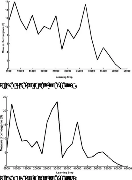
In the algorithm random initial states were created by changing load of some buses between ±30% of their normal loadings and also by outage of some transmission lines, all in random. The algorithm executed for various busbars and it was observed that after about 52500 epochs for agent 15 and 62500 epochs for agent 14, the algorithm converged successfully to stable and near optimal solutions. Figs. 4 and 5 present the results of variations of the D value at nodes 15 and 14, respectively.
After the agents learned successfully, they can work on-line and directly in the power system and adapt themselves with real environment and real rewards.
Another important issue in our application is that the number of SAs in the system varies in time, therefore the state vector may have different sizes in different system conditions and the algorithm cannot work with this situation. To remedy this problem we propose the following solution. Implement a repository of learned ⎪ ⎪ ⎪ ⎪ ⎩ ⎪ ⎪ ⎪ ⎪ ⎨ ⎧ − = − ≠ − − − − − − − =
∑
∑
∑
∑
= = = = diverged loadflo the if stat final stat the if Q w stat final stat the if v v Q w v v w v v w r s ks c s
c s n i i q k ref n i n j n i si q cj r c s ref s k 100 1
agents for each BA or SA in the network which learned with different number of SAs available on the network. Each agent in the network based on the available SAs, selects an appropriate learned agent from the repository. The repository constructed with different numbers and different combination of SAs in the power system.
Figure 4: Learning result of agent 15.
Figure 5: Learning result of agent 14.
6. SIMULATION
The objective of setting up these examples is to demonstrate ideas and methods for implementing the coordinated voltage control to eliminate voltage violations in system contingencies.
Since JADE has been selected as the platform of agent development, an interface for linking power simulation environment with JADE or another solution is required.
The solution is to implement power system in Java language and simply integrating it with JADE as a simple agent. InterPSS engine without its graphical user interface
was used in this study. InterPSS is an open source
development project aimed to develop an Internet technology based software system for design, analysis, and simulation of power systems [20]. The APIs of InterPSS successfully integrated in JADE and by this approach the interfacing problem solved by an integrating mechanism. As mentioned in the previous section, the load flow agent which plays the role of power system simulation environment is constructed by integrating the
InterPSS engine in one of the JADE’s agents. So, communications between agents and the power system can be carried out merely by message passing capabilities of JADE. This method is the best choice for MAS application because of its acceptable performance and high speed of data. Furthermore, it is platform-independent.
To test the multi-agent collaboration protocol in the IEEE 39 Bus New England Power System of Fig. 3, each agent was trained by RL. In the simulation, steady-state model of the IEEE 39-buses power system was used. In test cases it has been assumed that there are only four available SA at buses 13, 14, 33 and 37. The busbars 12 and 16 were selected as critical bus.
The algorithm in this work was implemented in Java. After compilation, the Java code can be executed through agents on the PCs. The PCs are connected to one Fast Ethernet switch. Many simulations have been carried out to verify the operation and effectiveness of multi-agent system and RL algorithm. Three different tests have been selected for presentation in this section.
Test 1: At the 1st second of the simulation, the load at node 15 increased by 10% which led to voltage drop at
node 15. At the 2nd seconds of the simulation, the
transmission line between nodes 15 and 16 was lost that led to a voltage drop at node 15 below the constraint of 0.95 p.u. The agent located at node 15 detects this voltage violation. It searches the DF for available SAs and finds SA13, SA14, SA33 and SA37. Then, the BA15 sends CFP for these SAs and since all of the SAs are in normal mode, they reply to it with the proposal message and collaboration amount. The BA15 calls the DM unit to provide the best action vector for this state. The DM decides the action vector of (0.0, -1.50, 0.0, 0.0) which means that only SA14 must inject the reactive power of 1.50 p.u. This decision is in compliance with topology of network in which SA14 is the nearest SA in the network to bus agent 15. BA15 sends a request for reactive power injection to SA14 at node 14. The action of this SA at the
3rd second increased the voltage at node 15 and cleared
TABLE 2
THE VOLTAGE MAGNITUDE OF SOME BUSBARS IN TEST 1.
Voltage in p.u. Bus
Name Normal condition Before action After actions
Bus11 1.01219 0.99108 1.00545
Bus12 0.9996 0.97452 0.99144
Bus13 1.01372 0.98598 1.00457
Bus14 1.01096 0.97044 0.99765
Bus15 1.01419 0.92448 0.95349
Bus16 1.03042 1.04024 1.04243
Bus17 1.03234 1.03449 1.0380
Bus18 1.02975 1.0262 1.03123
Bus30 1.01665 0.99429 1.00938
Bus32 1.02905 1.01785 1.02532
Bus33 1.0031 0.9769 0.99433
Bus34 1.00479 0.98553 0.99866
Bus35 1.00719 0.98888 1.0014
Bus36 0.99653 0.97878 0.99095
Bus37 0.99556 0.97816 0.99009
Figure 6: Simulation result of test 1.
Test 2: At the 1st second of the simulation, the load at node 15 increased by 20% which led to a voltage drop at node 15. Also because of exceeding power transfer limit
of the line between nodes 15 and 16, at the 2nd seconds,
this transmission line was lost. Because of this line outage, the voltage at node 15 was dropped to 0.914 p.u. The agent located at node 15 detected this voltage violation. Like the test case I, the BA15 calls the DM unit for a proper action vector which is (-0.75, -1.50, 0.0, 0.0) and means that not only SA14 must inject 1.50 p.u but also SA13 must inject 0.75 p.u reactive power. Fig. 7
shows that at the 3rd seconds by action of SA14 the
voltage arises to 0.943 p.u and it is still below the acceptable voltage of 0.95 p.u. However, by action of SA13 (which is assumed to be done at 3.2 seconds for better understanding of insufficiency of only single agent action) the voltage violation is successfully cleared. Voltage changes of some busbars during the test are shown in Table 3.
Figure 7: Simulation result of test 2.
TABLE 3
THE VOLTAGE MAGNITUDE OF SOME BUSBARS IN TEST 2.
Voltage in p.u. Bus
Name
Normal condition
Before actions
After 1st
action
After 2nd
action
Bus11 1.01219 0.988 1.003 1.010 Bus12 0.9996 0.971 0.988 0.998 Bus13 1.01372 0.982 1.001 1.012 Bus14 1.01096 0.965 0.993 1.002 Bus15 1.01419 0.914 0.943 0.953 Bus16 1.03042 1.040 1.042 1.043 Bus17 1.03234 1.034 1.037 1.039 Bus18 1.02975 1.025 1.030 1.032 Bus30 1.01665 0.991 1.007 1.015 Bus32 1.02905 1.016 1.024 1.027 Bus33 1.0031 0.973 0.991 0.998 Bus34 1.00479 0.983 0.996 1.002 Bus35 1.00719 0.986 0.999 1.005 Bus36 0.99653 0.976 0.989 0.994 Bus37 0.99556 0.976 0.988 0.993
Test 3: At the 1st second of the simulation, the load at node 15 increased by 30% leading to a voltage drop at node 15. At the 2nd seconds, the transmission line between
nodes 13, 14 and 33 perform local actions of 1.125, -1.125 and -0.375 p.u respectively. By performing these actions, all of the SAs go to servicing mode and register in DF again. At this time the BA15 finds all of the SAs and asks them their collaboration values. The SAs at nodes 13, 14 and 33 reply the BA15 with the proposal of -0.375, -0.375 and -1.125 p.u reactive powers. After that, the DM at node 15 decides the action vector of (0.375, -0.375, --0.375, 0.0) which means reactive power injection of 0.375 p.u by STATCOMs at nodes 13, 14 and 33. From Fig. 8, we can see that the voltage violation eliminated successfully by collaboration of three SAs at
5th second. Voltage changes of some busbars during the
test are shown in Table 4.
Simulation results in three test cases above show the effectiveness of the proposed voltage control mechanism in eliminating voltage violations in various system contingencies.
The advantage of this method respecting method described in [3] is that time elapsed to eliminate voltage
violation is shorter and also decisions that made by agents are more optimum. Indeed, reactive power reserve is considered which causes increasing reliability and robustness of system in contingency situations. Furtheremore, the list of available servicing agents in this method is dynamic and is generated automatically.
Figure 8: Simulation result of test 3.
TABLE 4
THE VOLTAGE MAGNITUDE OF SOME BUSBARS IN TEST 3.
Voltage in p.u. Bus
Name Normal condition
Before actions
After 1st
action
After 2nd
action
After 3rd
action
After 4th
action
After 5th
action
After 6th
action Bus11 1.01219 0.980 0.991 1.001 1.004 1.008 1.011 1.013 Bus12 0.9996 0.927 0.955 0.977 0.981 0.989 0.996 1.000 Bus13 1.01372 0.910 0.953 0.984 0.990 1.002 1.012 1.017 Bus14 1.01096 0.907 0.941 0.974 0.981 0.990 1.001 1.007 Bus15 1.01419 0.844 0.882 0.918 0.925 0.936 0.947 0.953 Bus16 1.03042 1.035 1.038 1.040 1.041 1.042 1.043 1.044 Bus17 1.03234 1.027 1.031 1.035 1.036 1.037 1.039 1.040 Bus18 1.02975 1.015 1.021 1.027 1.029 1.030 1.032 1.034 Bus30 1.01665 0.991 1.001 1.010 1.012 1.015 1.018 1.020 Bus32 1.02905 1.001 1.010 1.019 1.021 1.024 1.026 1.029 Bus33 1.0031 0.939 0.959 0.979 0.986 0.992 0.998 1.004 Bus34 1.00479 0.964 0.977 0.989 0.993 0.997 1.001 1.004 Bus35 1.00719 0.970 0.982 0.993 0.997 1.000 1.004 1.007 Bus36 0.99653 0.960 0.972 0.983 0.986 0.990 0.993 0.996 Bus37 0.99556 0.959 0.971 0.982 0.985 0.989 0.992 0.995 7. CONCLUSION
Simulation results of this study show that the proposed multi-agent based secondary voltage control scheme equipped with RL algorithm is very effective and rapid in managing global voltage profile of power systems in voltage violation problems. By using intelligent, adaptive, autonomous and cooperative agents utilized with RL algorithm, the overall system performance was remarkably increased. The SARSA as an on-policy RL
algorithm was implemented and worked well to make optimal or near optimal decisions for managing reactive power resources in power systems. Using JADE for implementation of MAS in the power systems, performance of method was verified in a real communication simulation. In addtion, InterPSS engine was successfully integrated in JADE and tested in many simulations.
8. REFERENCES
[1] H. Lefebvre, D. Fragnier, and J. Y. Boussion, “Secondary coordinated voltage control system: Feedback of EDF”, in Proc. IEEE/PES Summer Meeting, Seattle, USA, July, 2000, pp. 291-295.
[2] H. F. Wang, “Multi-agent co-ordination for the secondary voltage control in power system contingencies,” in Proc. Inst. Elect. Eng. C, 2001, pp. 61–66.
[3] Hai Feng Wang,, H. Li, and H. Chen “Coordinated Secondary Voltage Control to Eliminate Voltage Violations in Power System Contingencies,” IEEE Trans. on Power Systems, Vol. 18, No. 2, May 2003.
[5] J. P. Paul and J. Y. Leost, “Improvements of the secondary voltage control in France,” in IFAC Symp. on Power Syst. Power Plants Control, Beijing, China, 1986.
[6] Mats Larsson, “Coordinated Voltage Control in Electric Power Systems,” Doctoral Dissertation, Lund University, Sweden, 2000, pp55-60.
[7] Sheng Gehao, Jiang Xiuceng, and Zeng Yi , “Optimal Coordination For Multi-Agent Based Secondary Voltage Control in Power System,” IEEE/PES Transmission and Distribution Conference & Exhibition: Asia and Pacific, Dalian, China, 2005.
[8] JADE – Java Agent DEvelopment Framework, see: http://jade.tilab.com/
[9] Foundation for Intelligent Physical Agents (FIPA), see: http://www.fipa.org/.
[10] D. P. Bertsekas and J. N. Tsitsiklis, Neuro-Dynamic Programming. Belmont, MA: Athena Scientific, 1996.
[11] L. P. Kaelbling, M. L. Littman, and A. W. Moore, “Reinforcement learning: A survey,” J. Artif. Intell. Res., vol. 4, pp. 237–285, Jan.– June 1996.
[12] R. S. Sutton and A. G. Barto, “Reinforcement learning: An introduction,” Adaptive Computations and Machine Learning, 1998.
[13] J. G. Vlachogiannis and N. D. Hatziargyriou, “Reinforcement Learning for Reactive Power Control,” IEEE Trans on Power System, Vol. 19, No. 3, August 2004.
[14] C.Rehtanz, “Autonomous Systems and Intelligent Agents in Power System Control and Operation” , Springer , ISBN 3-540-40202-0. [15] Russell, S. J. and Norvig, “Artificial Intelligence: a Modern
Approach”, Prentice Hall, 2nd edition, 2003.
[16] M.Wooldridge, “An Introduction to Multi-agent Systems”, Wiley Press, May 2002
[17] KAI HUANG, “Shipboard Power System Reconfiguration Using Multi-Agent System”, Ph.D. dissertation, Dept. Elec. Eng., The Florida State University, summer 2007.
[18] J. M. Solanki,N. N. Schulz, “Using Intelligent Multi-agent System for Shipboard Power Systems Reconfiguration”, Proceedings of the 13th International Intelligent Systems Application to Power Systems, Nov. 2005.
[19] D.P. Buse , Q.H.Wu, “ " IP network-based multi-agent systems for industrial automation : information management, condition monitoring and control of power systems”, SPRINGER, 2007, ISBN 978-1-84628-646-9.
[20] InterPSS Power System Simulation Project, see: http://www.interpss.org
![Figure 1: Agent execution in JADE [8]](https://thumb-us.123doks.com/thumbv2/123dok_us/19815.2002097/3.612.321.532.455.705/figure-agent-execution-in-jade.webp)